OF8-NEX1Medical telemetry receiver
Life Sensing Instruments, Inc.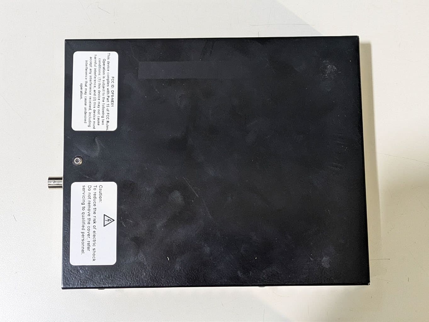
Click to zoom
Application Details
- Equipment Class
- DSS - Part 15 Spread Spectrum Transmitter
- Date of Grant
- Aug 31, 2026
- Application Purpose
- Original Equipment
- Equipment Note
- Medical telemetry receiver
- Frequency Range
- 910.00000000 - 920.00000000
- Country
- United States
Documents & Files
Document Text
Text extracted from the exhibit documents filed with the FCC. Open a document above to read the original.
Users Manual
Life Sensing Instruments, Inc. | CONFIDENTIAL Pg. 1 NEXUS TELEMETRY RECEIVER Operator’s Manual Life Sensing Instruments, Inc. December 15, 2025 Life Sensing Instruments, Inc. | CONFIDENTIAL Pg. 2 Nexus Telemetry Receiver Overview The Nexus Telemetry Receiver is a component of a patient monitoring system designed to enable bi-directional wireless communication between telemetry patient-worn transmitters and a Central Station computer. Upon receiving the telemetry signals from the transmitters via the WMTS transmission band, the Nexus forwards the data over a wired USB connection to the Central Station computer, which hosts specialized software for displaying and analyzing vital sign data. The Nexus can be powered by an external AC power adapter or by using Power Over Ethernet (PoE). The receiver operates in conjunction with an external antenna system to establish wireless links with patient-worn telemetry transmitters. Theses transmitters collect vital sign data and transmit the data via the 608 – 614, 1395 – 1400, and 1427 – 1432 MHz Wireless Medical Telemetry Service (WMTS) bands to the receiver. The Nexus supports downstream communication back to the transmitters over the ISM band (910–920 MHz), enabling limited bi-directional control or configuration updates where applicable. External Ports The NEXUS has (4) ports at the rear of the housing. • ETHERNET: This port can be used for PoE (optional). • USB: This port is used for communication between the Central Station computer and the Nexus. • POWER: This port is used to power the device using an external AC power adapter. • BNC: This port is used to connect to the antenna using LMR-240 cable. LED Status Indicators The NEXUS has (4) LED lights on the front of the housing. • Green LED (RIGHT) : Power: The LED indicates that the NEXUS is powered on. • Green LED: Firmware: The LED will blink to indicate that the firmware is running. • Yellow LED: Communication: The LED will blink as data is received from the transmitters. • Red LED: Fault: The Red LED indicates a fault condition. When the Red LED is displayed, the Nexus cannot be used. Instructions for Use The Nexus Telemetry Receiver requires no user interaction for use. There are no configuration requirements. Connecting the USB Cable Insert the “A” end of the USB A to B cable into the port labeled “Data” on the back of the Nexus. Insert the “B” end of the USB A to B cable into the port labeled “Nexus” on the back of the Central Station computer. Powering on the Nexus (AC Power Adapter) Insert the barrel jack connector on the AC power adapter into the port labeled “Power” on the back of the Nexus. Plug the AC power adapter’s power cord into the electrical outlet. The Nexus will automatically power on without user interaction. The Nexus will transmit on the ISM band automatically upon powering on. Powering on the Nexus (POE) Insert the Ethernet connector from the PoE-enabled network switch or PoE injector into the port labeled “Ethernet” on the back of the Nexus. The Nexus will automatically power on when a valid PoE connection is established and will begin transmitting on the ISM band without user interaction. Life Sensing Instruments, Inc. | CONFIDENTIAL Pg. 3 Antenna and Professional Installation Information Antenna Installation and Authorized Use: The Nexus Telemetry Receiver (Model NEXUS, FCC ID: OF8-NEX1) is designed for operation only with the antenna(s) supplied or expressly approved by Life Sensing Instruments, Inc. Authorized Antenna: • Manufacturer: LSI • Type: PIFA (50 Ω, BNC male connector) • Gain: 1.8 dBi • Cable: LMR-240 Substitution of other antennas, cables, or connectors is not permitted without the express written approval of Life Sensing Instruments, Inc. Use of unauthorized antennas may void the equipment authorization and the user’s authority to operate the device. Professional Installation Requirement: Installation, configuration, and range validation must be performed only by trained personnel authorized by Life Sensing Instruments, Inc. The professional installer shall: 1. Mount the antenna in accordance with the site plan and coverage documentation. 2. Connect the Nexus Telemetry Receiver and antenna with approved components without any modifications to components (BNC connector, LMR-240 cable, and antenna) 3. Verify field strength coverage and log the installation record in accordance with procedures. The Nexus Telemetry Receiver is not intended for consumer or residential installation. Support Services The authorized support provider for the Nexus Telemetry Receiver is Life Systems International (LSI), located in Charlotte, NC. Support services include hardware support available through the Repair Depot. To learn more about the support services offered by LSI, call 800-846-1279 x1. Repair Depot For repair services of the Nexus Telemetry Receiver, contact the authorized support provider: LSI Attn: Repair Depot 2102 Cambridge Beltway Dr., Ste. A Charlotte, NC 28273 800-846-1279 x1 [email protected] Life Sensing Instruments, Inc. | CONFIDENTIAL Pg. 4 Nexus Telemetry Receiver Specifications MECHANICAL PHYSICAL DIMENSIONS (WxHxD) 6.85" W X 1.44" x H 8.26" D WEIGHT 1.75 lbs ANTENNA CONNECTION IMPEDENCE 50 OHM CONNECTOR BNC, FEMALE DATA USB B - PROTOCOL USB 2.0 USB B - TRANSMISSION RATE BAUD RATE: 921600 / BANDWIDTH: 75 KBPS USB B - CONNECTOR TYPE USB B ELECTRICAL INPUT VOLTAGE - AC POWER 100 TO 240 VAC FREQUENCY - AC POWER 50Hz/60Hz WIRELESS MODULATION 4GFSK (WMTS), FSK 150 kHz (ISM) FREQUENCY BAND (RECEIVING) 608.00-614.00, 1395.00-1400.00, 1427.00-1432.00 MHz FREQUENCY BAND (TRANSMIT) 910.00 – 920.00 MHz CHANNEL SPACING 75 kHz Antenna Specifications MECHANICAL DIMENSIONS L X W X H 7.1” L x 4.2” W x 1” H CONNECTOR BNC (THROUGH HOLE) COAX CABLE LMR-240 MOUNT CEILING ELECTRICAL GAIN (PEAK) 1.8 dBi VSWR (MAX) < 2.0:1 POLARIZATION LINEAR (HORIZONTAL ORIENTATION PREFERRED) IMPEDANCE 50 OHM TYPE PIFA (PLANAR INVERTED-F ANTENNA) INDOOR/OUTDOOR INDOOR USE ONLY Life Sens…
Text truncated - open the document above for the full version.
Cover Letter(s)
Life Sensing Instruments, Inc. Professional Installation Justification — Nexus Telemetry Receiver Summary: While the connector type is physically standardized (BNC 50 Ω), the system’s function, regulatory classification, and installation environment clearly limit its use to professional medical installation only. Overview: This equipment is a medical telemetry receiver that forms part of a hospital-based patient monitoring system. It is not marketed or distributed for general consumer use and is intended solely for use in controlled clinical environments. The following addresses each element of FCC Guidance 353028: (1) Hardware Availability The equipment is not available to the general public. It is distributed exclusively through a single authorized distributor to licensed healthcare facilities (e.g., hospitals and outpatient rehabilitation centers) for use within an integrated medical telemetry system. The product is not offered via retail, mail order, or consumer e-commerce channels. It is supplied only as part of a regulated medical device ecosystem and requires configuration with other proprietary hardware and software components before it can function. (2) Marketing Limitations The system is not marketed to consumers. All sales are made directly to hospitals or clinics by the authorized distributor. Installation and coverage verification are conducted by trained service personnel or factory-certified technicians. No end-user or consumer installation is permitted or supported. (3) Intended Use The device’s intended use is medical telemetry within clinical and hospital settings. It operates as part of a closed medical system. The device is not suitable for general public or residential use, as its installation and operation require integration with hospital network infrastructure, frequency coordination within WMTS bands, and compliance with medical-specific EMC and safety standards. (4) Professional Installation Requirement Although the RF output uses a standard 50 Ω BNC connector, professional installation is required for the following reasons: • System-Level Integration: The antenna connection is one element of a larger hospital telemetry network that requires RF coverage mapping and validation by trained personnel to ensure compliance with performance and safety requirements. • Specialized Site Planning: Installation involves placement and alignment of the telemetry receiver and antenna in the facility to achieve adequate coverage. • No Consumer Adjustments: The antenna interface is used only for connecting approved, manufacturer- supplied antennas during installation. There are no provisions or controls allowing the end-user to substitute or modify the antenna or transmission characteristics.
External Photos
F2X35437C Page 1 of 5 2025-09-23 PHOTOGRAPHS: EXTERNAL Life Sensing Instruments Inc. – Nexus Order No(s): F2X35437C Applicant: Life Sensing Instruments Inc. Model: Nexus F2X35437C Page 2 of 5 2025-09-23 Order No(s): F2X35437C Applicant: Life Sensing Instruments Inc. Model: Nexus F2X35437C Page 3 of 5 2025-09-23 Top View Bottom View Order No(s): F2X35437C Applicant: Life Sensing Instruments Inc. Model: Nexus F2X35437C Page 4 of 5 2025-09-23 Antenna: Front View Antenna: Rear View Order No(s): F2X35437C Applicant: Life Sensing Instruments Inc. Model: Nexus F2X35437C Page 5 of 5 2025-09-23 Antenna – Side 1 Antenna – Side 2
ID Label/Location Info
Life Sensing Instruments, Inc. | CONFIDENTIAL Nexus Telemetry Receiver: FCC Label Label Size: 1.25” H x 2.25” W Life Sensing Instruments, Inc. | CONFIDENTIAL Nexus Telemetry Receiver: FCC Label Location Label is applied on top cover of housing
Internal Photos
Life Sensing Instruments, Inc. | CONFIDENTIAL Nexus Telemetry Receiver: Internal Photos Life Sensing Instruments, Inc. | CONFIDENTIAL Life Sensing Instruments, Inc. | CONFIDENTIAL F2X35437C Page 1 of 5 2025-09-23 PHOTOGRAPHS: INTERNAL Life Sensing Instruments Inc. – Nexus Order No(s): F2X35437C Applicant: Life Sensing Instruments Inc. Model: Nexus F2X35437C Page 2 of 5 2025-09-23 Order No(s): F2X35437C Applicant: Life Sensing Instruments Inc. Model: Nexus F2X35437C Page 3 of 5 2025-09-23 Radio Module Order No(s): F2X35437C Applicant: Life Sensing Instruments Inc. Model: Nexus F2X35437C Page 4 of 5 2025-09-23 Radio Module, cont’d Order No(s): F2X35437C Applicant: Life Sensing Instruments Inc. Model: Nexus F2X35437C Page 5 of 5 2025-09-23 Antenna – Front View Antenna – Rear View
RF Exposure Info
20240420 Report Number: F2X35437C-02E Page 1 of 8 Issue Date: 2025-12-15 F2 Labs 16740 Peters Road Middlefield, Ohio 44062 United States of America www.f2labs.com MPE REPORT Manufacturer: Life Sensing Instruments Inc. 2102 Cambridge Beltway Drive, Suite A1 Charlotte, North Carolina 28273 USA Applicant: Same as Above Product Name: Nexus Telemetry Receiver Product Description: The Nexus Receiver is a medical telemetry receiver designed to operate in healthcare environments. It receives data in the WMTS (Wireless Medical Telemetry Service) band and transmits data via the ISM band (910–920 MHz) for downstream processing. Model: Nexus FCC ID: OF8-NEX1 Testing Commenced: 2025-09-09 Testing Ended: 2025-12-15 Test Results: In Compliance The EUT complies with the EMC requirements when manufactured identically as the unit tested in this report, including any required modifications. Any changes to the design or build of this unit subsequent to this testing may deem it non- compliant. Standards: • KDB447498 • FCC 1.1310 Order No(s): F2X35437C Applicant: Life Sensing Instruments Inc. Model: Nexus 042216 Report Number: F2X35437C-02E Page 2 of 8 Issue Date: 2025-12-15 Evaluation Conducted by: Erik Tobin, EMC Engineer Report Reviewed by: Ken Littell, Vice President of Operations F2 Labs F2 Labs F2 Labs 26501 Ridge Road 16740 Peters Road 8583 Zionsville Road Damascus, MD 20872 Middlefield, OH 44062 Indianapolis, IN 46268 Ph 301.253.4500 Ph 440.632.5541 Ph 317.610.0611 This test report may be reproduced in full; partial reproduction only may be made with the written consent of F2 Labs. The results in this report apply only to the equipment tested. Order No(s): F2X35437C Applicant: Life Sensing Instruments Inc. Model: Nexus 042216 Report Number: F2X35437C-02E Page 3 of 8 Issue Date: 2025-12-15 TABLE OF CONTENTS 1 ADMINISTRATIVE INFORMATION 2 SUMMARY OF TEST RESULTS/MODIFICATIONS 3 ENGINEERING STATEMENT 4 EUT INFORMATION AND DATA 5 RF EXPOSURE FOR DEVICE >20cm FROM HUMAN FCC Order No(s): F2X35437C Applicant: Life Sensing Instruments Inc. Model: Nexus 042216 Report Number: F2X35437C-02E Page 4 of 8 Issue Date: 2025-12-15 1 ADMINISTRATIVE INFORMATION 1.1 Measurement Location: F2 Labs in Middlefield, Ohio. Site description and attenuation data are on file with the FCC's Sampling and Measurement Branch at the FCC Laboratory in Columbia, MD. 1.2 Measurement Procedure: All measurements were performed according to: • KDB558074 • FCC 15.247 1.4 Document History Document Number Description Issue Date Approved By F2X35437C-03E First Issue 2025-12-15 K. Littell Order No(s): F2X35437C Applicant: Life Sensing Instruments Inc. Model: Nexus 042216 Report Number: F2X35437C-02E Page 5 of 8 Issue Date: 2025-12-15 2 SUMMARY OF TEST RESULTS Test Name Standard(s) Results RF Exposure for Device >20cm from Human KDB447498 FCC 1.1310 Complies Modifications Made to the Equipment None Order No(s): F2X35437C Applicant: Life Sensing Instruments Inc. Model: Nexus 042216 Report Number: F2X35437C-02E Page 6 of 8 Issue Date: 2025-12-15 3 ENGINEERING STATEMENT This report has been prepared on behalf of Life Sensing Instruments Inc. to provide documentation for the calculations described herein, based on the measurements taken in supporting Test Reports. This equipment has been tested, and calculations were found to comply with KDB447498 and FCC 1.1310. The test results found in this test report relate only to the item(s) tested. Order No(s): F2X35437C Applicant: Life Sensing Instruments Inc. Model: Nexus 042216 Report Number: F2X35437C-02E Page 7 of 8 Issue Date: 2025-12-15 4 EUT INFORMATION AND DATA 4.1 Equipment Under Test: Product: Nexus Telemetry Receiver Model(s): Nexus Serial No.: 1205 Software Versions: Rev 46 and Rev 25 FCC ID: OF8-NEX1 4.2 Trade Name: Life Sensing Instruments Inc. 4.3 Power Supply: SL Power model ME30A1203F01 4.4 Applicable Rules: • KDB447498 • FCC 1.1310 4.5 Antenna: PIFA (External), 1.8dBi Gain 4.6 Accessories: Device Manufacturer Model Number Serial Number Laptop Lenovo None Specified None Specified Accessory Software Version: TeraTerm V4.105 Order No(s): F2X35437C Applicant: Life Sensing Instruments Inc. Model: Nexus 042216 Report Number: F2X35437C-02E Page 8 of 8 Issue Date: 2025-12-15 5. RF EXPOSURE FOR DEVICE >20cm FROM HUMAN 5.1 Requirements: Distance used is 20cm FCC Limit: 1mW/cm 2 Formula used for result: E.I.R.P. 4 π R2 Results: E.I.R.P. = 7.160mW 7.160mW at the 920 MHz High Channel (highest) 7.160mW = 7.160mW = 0.0014mW/cm2 4 π R 2 5026.55
Test Report
Life Sensing Instruments, Inc. | CONFIDENTIAL Nexus Telemetry Receiver Unlicensed Transmitters: Approved Antennas List Manufacturer Antenna Description Type Peak Gain (dBi) Min Cable loss (dB) Ω Connector Type Notes Life Sensing Instruments, Inc. Nexus Telemetry Receiver Antenna PCB PIFA 1.8 .076 50 BNC 1 Notes: 1) Loss is based on 12” LMR-240 cable (0.076 dB per foot) Life Sensing Instruments, Inc. | CONFIDENTIAL Nexus Telemetry Receiver Antenna Specification Mechanical Dimensions L x W x H 7.1” x 4.2” x 1” Operating Temperature 10 o C - 45 o C Connector BNC (through hole) Coax Cable LMR-240 Mount Ceiling Ceiling Mounting Hardware Nylon bolts and wingnuts Electrical Gain (Peak) 1.8 dBi VSWR (Max) < 2.0:1 Polarization Linear (Horizontal Orientation Preferred) Impedance 50 Ohm Type PIFA (Planar Inverted-F Antenna) Range (Max) 200’ Range (Optimal) 5’ – 75’ Indoor/Outdoor Indoor use only Prepared By: P. Chrisler Classification: Confidential/Proprietary Date: 7/12/2022 Review By: D. Myer Document Number: LSI-0015 Remarks: Approved by: S. Sanders Revision: A Page 1 of 29 This document is Sanders RF confidential and proprietary and solely for use by Sanders. The document and arrangement thereof, and all contents are Copyright 2011 by Sanders RF Consulting, LLC. ALL RIGHTS RESERVED. Any use of this document, including reproduction, modification, distribution or republication, without the prior written consent of Sanders, is strictly prohibited. LSI Baseline Antenna Gain and Patterns LSI provided an antenna assembly for antenna gain and pattern measurements. The PCB was labeled LSI Antenna Board EP2. This measurement was done to qualify the LSI antenna. Measurements were open site and performed at the following five frequencies (center of each band): • 611 MHz • 915 MHz • 1397 MHz • 1430 MHz • 2441 MHz LSI Antenna Board EP2 in prototype housing: Prepared By: P. Chrisler Classification: Confidential/Proprietary Date: 7/12/2022 Review By: D. Myer Document Number: LSI-0015 Remarks: Approved by: S. Sanders Revision: A Page 2 of 29 This document is Sanders RF confidential and proprietary and solely for use by Sanders. The document and arrangement thereof, and all contents are Copyright 2011 by Sanders RF Consulting, LLC. ALL RIGHTS RESERVED. Any use of this document, including reproduction, modification, distribution or republication, without the prior written consent of Sanders, is strictly prohibited. LSI Antenna Orientation: Flat Side Upright Prepared By: P. Chrisler Classification: Confidential/Proprietary Date: 7/12/2022 Review By: D. Myer Document Number: LSI-0015 Remarks: Approved by: S. Sanders Revision: A Page 3 of 29 This document is Sanders RF confidential and proprietary and solely for use by Sanders. The document and arrangement thereof, and all contents are Copyright 2011 by Sanders RF Consulting, LLC. ALL RIGHTS RESERVED. Any use of this document, including reproduction, modification, distribution or republication, without the prior written consent of Sanders, is strictly prohibited. Results Peak gains are in bold font. Peak Antenna Gain (dBi) Summary 611MHz: Orientation Flat Side Upright Polarization Horizontal Vertical Horizontal Vertical Horizontal Vertical Peak Gain +5.8 -8.2 +3.6 -1.0 +5.4 -1.4 dBi Peak Antenna Gain (dBi) Summary 915MHz: Orientation Flat Side Upright Polarization Horizontal Vertical Horizontal Vertical Horizontal Vertical Peak Gain +1.5 -8.3 -6.0 +1.8 +0.7 -0.9 dBi Peak Antenna Gain (dBi) Summary 1397MHz: Orientation Flat Side Upright Polarization Horizontal Vertical Horizontal Vertical Horizontal Vertical Peak Gain -1.4 -7.0 -3.4 +3.4 -8.6 -1.0 dBi Peak Antenna Gain (dBi) Summary 1430MHz: Orientation Flat Side Upright Polarization Horizontal Vertical Horizontal Vertical Horizontal Vertical Peak Gain -1.5 -7.6 -6.3 +1.3 -1.7 +0.7 dBi Peak Antenna Gain (dBi) Summary 2441MHz: Orientation Flat Side Upright Polarization Horizontal Vertical Horizontal Vertical Horizontal Vertical Peak Gain +2.3 -6.8 +5.3 -0.3 -7.8 +2.6 dBi Prepared By: P. Chrisler Classification: Confidential/Proprietary Date: 7/12/2022 Review By: D. Myer Document Number: LSI-0015 Remarks: Approved by: S. Sanders Revision: A Page 4 of 29 This document is Sanders RF confidential and proprietary and solely for use by Sanders. The document and arrangement thereof, and all contents are Copyright 2011 by Sanders RF Consulting, LLC. ALL RIGHTS RESERVED. Any use of this document, including reproduction, modification, distribution or republication, without the prior written consent of Sanders, is strictly prohibited. Antenna Patterns 611MHz Flat Orientation, planar cut with theta = 180⁰ Horizontal (max = +5.8dBi) Vertical (max = -8.2dBi) Prepared By: P. Chrisler Classification: Confidential/Proprietary Date: 7/12/2022 Review By: D. Myer Document Number: LSI-0015 Remarks: Approved by: S. Sanders Revision: A Page 5 of 29 This document is Sanders RF confidential and proprietary and solely for use by Sanders. The document and arrangement thereof, and all contents are Copyright 2011 by Sanders RF Consulting, LLC. ALL RIGHTS RESERVED. Any use of this document, including reproduction, modification, distribution or republication, without the prior written consent of Sanders, is strictly prohibited. Side Orientation, planar cut with phi = 0⁰ Horizontal (max = -1.0dBi) Vertical (max = +3.5dBi) Prepared By: P. Chrisler Classification: Confidential/Proprietary Date: 7/12/2022 Review By: D. Myer Document Number: LSI-0015 Remarks: Approved by: S. Sanders Revision: A Page 6 of 29 This document is Sanders RF confidential and proprietary and solely for use by Sanders. The document and arrangement thereof, and all contents are Copyright 2011 by Sanders RF Consulting, LLC. ALL RIGHTS RESERVED. Any use of this document, including reproduction, modification, distribution or republication, without the prior written consent of Sanders, is strictly prohibited. Upright Orientation, planar cut with phi = 90⁰ Horizontal (max = +5.4) Ver…
Text truncated - open the document above for the full version.
Test Report
20240912 Report Number: F2X35437C-01E Page 1 of 77 Issue Date: 2025-12-15 F2 Labs 16740 Peters Road Middlefield, Ohio 44062 United States of America www.f2labs.com CERTIFICATION TEST REPORT Manufacturer: Life Sensing Instruments Inc. 2102 Cambridge Beltway Drive, Suite A1 Charlotte, North Carolina 28273 USA Applicant: Same as Above Product Name: Nexus Telemetry Receiver Product Description: The Nexus Receiver is a medical telemetry receiver designed to operate in healthcare environments. It receives data in the WMTS (Wireless Medical Telemetry Service) band and transmits data via the ISM band (910–920 MHz) for downstream processing. Operating Voltage/Freq. of EUT During Testing: 120V/60 Hz Model: Nexus FCC ID: OF8-NEX1 Testing Commenced: 2025-09-09 Testing Ended: 2025-12-15 Summary of Test Results: In Compliance The EUT complies with the EMC requirements when manufactured identically as the unit tested in this report, including any required modifications and/or manufacturer’s statement. Any changes to the design or build of this unit subsequent to this testing may deem it non-compliant. Rules: • FCC Part 15 Subpart C, Section 15.247 • FCC15.207 - Conducted Limits • FCC Part 15.31(e) • ANSI C63.10-2020/Cor 1-2023 Order No(s): F2X35437C Applicant: Life Sensing Instruments Inc. Model: Nexus 20240912 Report Number: F2X35437C-01E Page 2 of 77 Issue Date: 2025-12-15 Evaluation Conducted by: Erik Tobin, EMC Engineer Report Reviewed by: Ken Littell, Vice President of Operations F2 Labs F2 Labs F2 Labs 26501 Ridge Road 16740 Peters Road 8583 Zionsville Road Damascus, MD 20872 Middlefield, OH 44062 Indianapolis, IN 46268 Ph 301.253.4500 Ph 440.632.5541 Ph 317.610.0611 This test report may be reproduced in full; partial reproduction only may be made with the written consent of F2 Labs. The results in this report apply only to the equipment tested. Order No(s): F2X35437C Applicant: Life Sensing Instruments Inc. Model: Nexus 20240912 Report Number: F2X35437C-01E Page 3 of 77 Issue Date: 2025-12-15 TABLE OF CONTENTS 1 ADMINISTRATIVE INFORMATION 2 SUMMARY OF TEST RESULTS/MODIFICATIONS 3 TABLE OF MEASURED RESULTS 4 ENGINEERING STATEMENT 5 EUT INFORMATION AND DATA 6 LIST OF MEASUREMENT INSTRUMENTATION 7 OCCUPIED BANDWIDTH 8 CONDUCTED OUTPUT POWER 9 VOLTAGE VARIATIONS 10 CONDUCTED SPURIOUS EMISSIONS 11 RADIATED SPURIOUS EMISSIONS 12 FREQUENCY SEPARATION 13 NUMBER OF CHANNELS 14 DWELL TIME 15 CONDUCTED EMISSIONS 16 TEST SETUP PHOTOGRAPHS Order No(s): F2X35437C Applicant: Life Sensing Instruments Inc. Model: Nexus 20240912 Report Number: F2X35437C-01E Page 4 of 77 Issue Date: 2025-12-15 1 ADMINISTRATIVE INFORMATION 1.1 Measurement Location: F2 Labs in Middlefield, Ohio. Site description and attenuation data are on file with the FCC's Sampling and Measurement Branch at the FCC Laboratory in Columbia, MD. 1.2 Measurement Procedure: All measurements were performed according to ANSI C63.10 and recommended FCC procedure of measurement under Section 15.247 and in KDB558074. A list of the measurement equipment can be found in Section 6. 1.3 Uncertainty Budget: The uncertainty in EMC measurements arises from several factors which affect the results, some associated with environmental conditions in the measurement room, the test equipment being used and the measurement techniques adopted. The measurement uncertainty budgets detailed below are calculated from the test and calibration data and are expressed with a 95% confidence factor. Note: Only measurements listed below which relate to tests included in this Test Report are applicable to it. This Uncertainty represents an expanded uncertainty expressed at approximately the 95% confidence level using a coverage factor of k=2. 1.4 Document History Document Number Description Issue Date Approved By F2X35437C-01E First Issue 2025-12-15 K. Littell Measurement Range Expanded Uncertainty Combined Uncertainty Radiated Emissions <1 GHz @ 3m ±5.07dB ±2.54dB Radiated Emissions <1 GHz @10m ±5.09dB ±2.55dB Radiated Emissions 1 GHz to 2.7 GHz ±3.62dB ±1.81dB Radiated Emissions 2.7 GHz to 18 GHz ±3.10dB ±1.55dB AC Power Line Conducted Emissions, 150kHz to 30 MHz ±2.76dB ±1.38dB Order No(s): F2X35437C Applicant: Life Sensing Instruments Inc. Model: Nexus 20240912 Report Number: F2X35437C-01E Page 5 of 77 Issue Date: 2025-12-15 2 SUMMARY OF TEST RESULTS Test Name Standard(s) Results Occupied Bandwidth CFR 47 Part 15.247(a)(2) / KDB558074 Complies Conducted Output Power CFR 47 Part 15.247(b)(2) / KDB558074 Complies Voltage Variations CFR 47 Part 15.31(e) Complies Conducted Spurious Emissions CFR 47 Part 15.247(d) / Part 15.207 / KDB558074 Complies Radiated Spurious Emission with 1.8dBi Gain Antenna CFR 47 Part 15.247(d) / Part 15.209 / KDB558074 Complies Peak Power Spectral Density CFR 47 Part 15.247(e) / KDB558074 N/A Frequency Separation ANSI 63.10 (7.8.2) Complies Number of Hopping Frequencies ANSI 63.10 (7.8.3) Complies Dwell Time ANSI 63.10 (7.8.4) Complies Conducted Emissions CFR 47 Part 15.207(a) Complies Modifications Made to the Equipment None Order No(s): F2X35437C Applicant: Life Sensing Instruments Inc. Model: Nexus 20240912 Report Number: F2X35437C-01E Page 6 of 77 Issue Date: 2025-12-15 3 TABLE OF MEASURED RESULTS Test Low Channel 910 MHz Mid Channel 915 MHz High Channel 920 MHz Conducted Output Power 4.227mW / 6.26dBm 3.811mW / 5.81dBm 4.732mW / 6.75dBm Conducted Output Power Limit 1 Watt / 30dBm 1 Watt / 30dBm 1 Watt / 30dBm E.I.R.P. with 1.8dBi Gain A ntenna 6.397 mW / 8.06dBm 5.770 mW / 7.61dBm 7.160 mW / 8.55dBm E.I.R.P. Limit 4 Watts / 36.02dBm 4 Watts / 36.02dBm 4 Watts / 36.02dBm -20dB Occupied Bandwidth 147.43 kHz 146.63 kHz 145.83 kHz 99% Occupied Bandwidth 171.47 kHz 176.28 kHz 173.08 kHz Occupied Bandwidth Limit 25 - 500 kHz 25 - 500 kHz 25 - 500 kHz Voltage Variations* Nominal: 120VAC -- -- -- -15% 4.256mW / 6.29dBm 4.207mW / 6.24dBm 4.753mW / 6.77dBm +15% 4.227mW / 6.26dBm 3.864mW / 5.87dBm 4.764mW / 6.78dBm Limit 1W / 30dBm 1W / 30dBm 1W / 30dBm *To meet…
Text truncated - open the document above for the full version.
Test Setup Photos
Order No(s): F2X35437C Applicant: Life Sensing Instruments Inc. Model: Nexus 20240912 Report Number: F2X35437C-01E Page 75 of 77 Issue Date: 2025-12-15 16 TEST SETUP PHOTOGRAPH(S) Radiated Spurious Emission: 0.009 MHz to 30 MHz Radiated Spurious Emission: 30 MHz to 1000 MHz Order No(s): F2X35437C Applicant: Life Sensing Instruments Inc. Model: Nexus 20240912 Report Number: F2X35437C-01E Page 76 of 77 Issue Date: 2025-12-15 Radiated Spurious Emission: Greater than 1 GHz Conducted Output Power, Occupied Bandwidth, and Conducted Spurious Emissions Order No(s): F2X35437C Applicant: Life Sensing Instruments Inc. Model: Nexus 20240912 Report Number: F2X35437C-01E Page 77 of 77 Issue Date: 2025-12-15 Conducted Emissions
Contact Information
Applicant
Korey Sixbury(President)
[email protected]Fax: 866-654-2542
Technical Contact
Life Sensing Instruments, Inc.Korey Sixbury
[email protected]Fax: (866) 554-2542
2102-A1 Cambridge Beltway Dr. · Charlotte, North Carolina, 28273 · United States
Test Firm
F2 LabsWendy Fuster
[email protected]Fax: 301-253-5179
Technical Specifications
| # | Rule Parts | Frequency Range | Power Output |
|---|---|---|---|
| 1 | 15C | 910 MHz - 920 MHz | 4.70 mW |
Other Applications from Life Sensing Instruments, Inc.
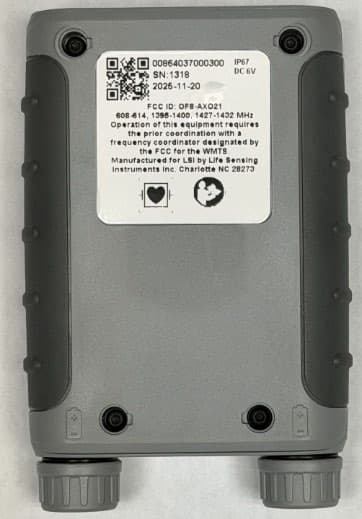
OF8-AXO21
Aug 31, 2026Medical telemetry transmitter
Equipment Class
TNB - Licensed Non-Broadcast Station Transmitter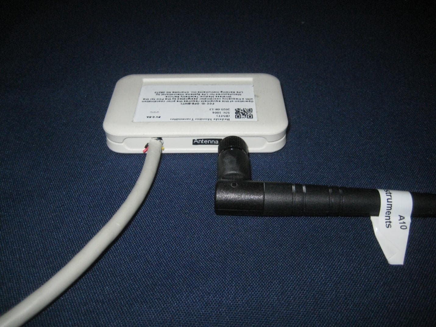
OF8-BMT1
Aug 31, 2026Bedside Wireless Transmitter
Equipment Class
TNB - Licensed Non-Broadcast Station Transmitter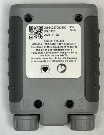
OF8-AX1
Aug 31, 2026Medical telemetry transmitter
Equipment Class
TNB - Licensed Non-Broadcast Station Transmitter
OF8-TM8B
Jan 30, 2003TM8B Dual ECG Transmitter
Equipment Class
TNT - Licensed Non-Broadcast Transmitter Worn on Body