OFZ90XX1RFID Reader
Wonderware Mobile Solutions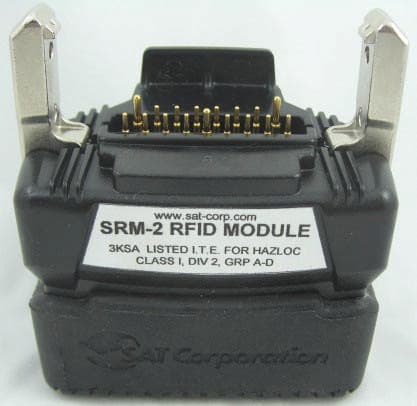
Click to zoom
Application Details
- Equipment Class
- DXX - Part 15 Low Power Communication Device Transmitter
- Date of Grant
- Jun 13, 2007
- Application Purpose
- Original Equipment
- Date of Application
- Jun 12, 2007
- Equipment Note
- RFID Reader
- Frequency Range
- 0.13400000 - 0.13400000
- Company
- Wonderware Mobile Solutions
- Country
- United States
Documents & Files
Document Text
Text extracted from the exhibit documents filed with the FCC. Open a document above to read the original.
Users Manual
Confidential & Proprietary Created by Clay Weston Page 1 of 2 Last revised:5/24/2007 SRM2-MC90XX User Guide Introduction This document provides important information regarding safety, regulatory compliance, and operation of the SAT SRM2-MC90XX RFID Module. The Module attaches to Symbol / Motorola MC9060 and MC9090 handheld computers to provide read/write access to SAT ST-1 tags and other tags employing 134 kHz TIRIS MPT technology. For application-specific information refer to the SAT Mobile IntelaTrac User Guide or other documentation appropriate to the software application being used. Safety and Regulatory Notices The following notices are required to ensure safe and proper use of the Module. Please read them carefully and contact SAT if you have any questions. This apparatus is suitable for use in Class I, Division 2 groups A-D, or unclassified or nonhazardous locations. This device may only be used in hazardous locations when connected in accordance with the control drawings SATDN 70213 and SATDN 70214. In hazardous locations, use only the handheld computer model numbers listed in the control drawings. Caution: Changes or modifications not expressly approved by SAT Corporation could void the user’s authority to operate the equipment. This device complies with Part 15 of the FCC Rules. Operation is subject to the following two conditions: (1) this device may not cause harmful interference, and (2) this device must accept any interference received, including interference that may cause undesired operation. FCC ID: OFZ90XX1 This Class [*] digital apparatus complies with Canadian ICES-003. Cet appareil numériqué de la classe B est conformé à la norme NMB-003 du Canada. IC: 6984A-90XX1 Following is a reproduction of the rear label: Operation The SRM2-MC90XX attaches to the bottom of Symbol/Motorola MC9060 and MC9090 series handheld computers. In hazardous locations, use only handheld computer model numbers listed on the control drawing (SATDN 70214). The module can be attached and detached in the hazardous area. LED Indicators Power to the module is controlled by software running on the host computer. When the host computer turns on power to the module both LEDs blink briefly, then stay off. When software initiates a read or write operation, the green LED flashes once. If the operation is successful, the green LED flashes again. If the operation fails, the red LED flashes. By default, the module will retry the operation ten times. If you see the green and red LEDs flashing alternately while attempting to read or write a tag, try repositioning the module. Range and Orientation The maximum range of the module is approximately 3” in the optimum orientation of reader to RFID tag. Imagine that the ST1 inspection tag (oriented horizontally, and with the label side facing the user) as a conventional circular clock. If the handheld computer itself (with the SRM-2 always facing the clock's center) were the clock's hour hand, the optimal positions for reading are between 2 and 3, or between 6 and 7, with the SRM-2 within an inch of the tag.
Cover Letter(s)
Declaration of RF Exposure Compliance RSS-102 Annex B [modified] ATTESTATION: In compliance to clause 2.4 of RSS-102, I attest that applicable measurement methods and evaluation methodologies have been followed and that the low power transmitter represented herein satisfies the exemption provisions of clause 2.5.1 or 2.5.2 of RSS-102. EXEMPTION CLAUSE APPLIED: FREQUENCY FIELD STRENGTH CALCULATED POWER (FRIIS) 0.134 MHz 33113 μ V/m @ 3 m -4.8 dBm (0.57 mW) NAME DATE Eric Lifsey 14 May 2007 TITLE EMC Engineer COMPANY Professional Testing (EMI) Inc. for SAT Corporation DEVICE IDENTIFIER 6984A-90XX1 *** 2.5.1
External Photos
07441-10 SAT SRM2 External Photos.doc Page 1 of 1 EUT External Photos: Front and Rear View (Note that the bottom is entirely covered in a rubber boot.) EUT as Attached (on right end) to Host Computer, Front View EUT as Attached (on right end) to Host Computer, Rear View ***
ID Label/Location Info
07441-10 SAT SRM2 Label Drawing.doc Page 1 of 1 ***
ID Label/Location Info
07441-10 SAT SRM2 Label Location.doc Page 1 of 1 Label Location ***
Internal Photos
07441-10 SAT SRM2 Internal Photos.doc Page 1 of 4 EUT with Cover Removed EUT, Partially Disassembled View (Shows Controller and Transceiver PCAs as mated per design.) 07441-10 SAT SRM2 Internal Photos.doc Page 2 of 4 Controller PCA Side 1 Controller PCA Side 2 07441-10 SAT SRM2 Internal Photos.doc Page 3 of 4 Transceiver PCA Side 1 Transceiver PCA Side 2 07441-10 SAT SRM2 Internal Photos.doc Page 4 of 4 Antenna, Loop ***
Test Report
07441-10 Page 1 of 15 Professional Testing (EMI) Inc. Project 07441-10 SAT Corporation SRM2-MC90XX Certification Electromagnetic Compatibility Test Report Prepared for: SAT Corporation 10111 Richmond Ave., Suite 650 Houston, TX 77042 By Professional Testing (EMI), Inc. 1601 FM 1460, Suite B Round Rock, Texas 78664 11 June 2007 Reviewed by Written by Jason Anderson Director, Test Services Eric Lifsey Test Engineer 07441-10 Page 2 of 15 Professional Testing (EMI) Inc. Table of Contents Title Page .........................................................................................................................................1 Table of Contents .............................................................................................................................2 Certificate of Compliance ................................................................................................................3 1.0 EUT Description ..................................................................................................................4 1.1 Applicable Documents.....................................................................................................4 1.2 EUT Operation.................................................................................................................4 2.0 Electromagnetic Emissions Testing .....................................................................................5 2.1 Radiated Emissions Measurements..................................................................................5 2.1.1 Test Procedure .........................................................................................................5 2.1.2 Test Criteria .............................................................................................................5 2.1.3 Test Results ..............................................................................................................6 2.1.4 Radiated Emissions Test Equipment < 30 MHz ......................................................6 2.1.5 Radiated Emissions Test Equipment 30 MHz to 1 GHz .........................................6 3.0 Occupied Bandwidth Measurements ...................................................................................6 4.0 Burst Length, Pulse Width, Pulse Repetition Rate and Duty Cycle ....................................6 5.0 Antenna Requirement ..........................................................................................................7 5.1 Evaluation Procedure .......................................................................................................7 5.2 Evaluation Criteria ...........................................................................................................7 5.3 Evaluation Results ...........................................................................................................7 6.0 Modifications .......................................................................................................................7 Appendix A Test Data Sheets.......................................................................................................9 Appendix B Policy, Rationale and Evaluation of EMC Measurement Uncertainty.......................................14 FIGURES Figure 1 Radiated Emissions Test Setup .........................................................................................8 NOTICE: (1) This Report must not be used to claim product endorsement, by NVLAP, NIST, the FCC or any other Agency. (2) This report also does not warrant certification by NVLAP or NIST. This report shall not be reproduced except in full, without the written approval of Professional Testing (EMI), Inc. The significance of this report is dependent on the representative character of the test sample submitted for evaluation and the results apply only in reference to the sample tested. The manufacturer must continuously implement the changes shown herein to attain and maintain the required degree of compliance. Revision History Rev 1 – Corrected emission limit for fundamental. Actual limit is higher than calculated. Pages 3 and 10 revised accordingly. EL 07441-10 Page 3 of 15 Professional Testing (EMI) Inc. Applicant: SAT Corporation Applicant’s Address: 10111 Richmond Ave., Suite 650 Houston, TX 77042 Project Number: 07441-10 Test Dates: 7 March 2007 I, Jason Anderson, for Professional Testing (EMI), Inc., being familiar with the FCC rules and test procedures have reviewed the test setup, measured data and this report. I believe them to be true and accurate. The EUT, a SAT Corporation, model SRM2-MC90XX was tested to and found to be in compliance with FCC Part 15 Subpart C for an Intentional Radiator. The highest emissions generated by the above equipment are listed below: Frequency (MHz) Level (dBμ μμ μV/m) Limit (dBμ μμ μV/m) Margin (dB) Fundamental 0.134 90.4 130.1 -39.7 Harmonics None measurable. n/a n/a n/a Spurious 347 34.0 37.0 -3.0 Occupied Bandwidth Not measured Transmit Duty Cycle 100 % assumed I, Jason Anderson, for Professional Testing (EMI), Inc., being familiar with the FCC rules and test procedures have reviewed the test setup, measured data and this report. I believe them to be true and accurate. Jason Anderson Regulatory Department Manager This report has been reviewed and accepted by SAT Corporation. The undersigned is responsible for ensuring that this device will continue to comply with the FCC and IC rules. C e r t i f i c a t e O f C o m p l i a n c e 07441-10 Page 4 of 15 Professional Testing (EMI) Inc. 1.0 EUT Description The SRM2-MC90XX (EUT) is a short range RFID transmitter/interrogator that queries RFID transponders used as asset tags in industrial applications. The EUT is a low-frequency RFID (Radio Frequency Identification) device for use with Texas Instruments TIRIS transponders. The EUT snaps on to the bottom end of a Symbol / Motorola handheld computer. The handheld computer provides 3.3V p…
Text truncated - open the document above for the full version.
Test Setup Photos
07441-10 SAT SRM2 Test Setup Photos.doc Page 1 of Setup Photos, Radiated Emissions from 130 kHz to 30 MHz 07441-10 SAT SRM2 Test Setup Photos.doc Page 2 of Setup Photos, Radiated Emissions 30 MHz to 1000 MHz Note – there are no mains conducted setup photos as this test was not required. ***
Contact Information
Applicant
Clay Weston(Manager, Hardware Development)
Technical Contact
Professinal Testing IncEric Lifsey
[email protected]512 244 3371
1601 B FM 1460 · Round Rock, Texas · United States
Non-Technical Contact
Professinal Testing IncJason Anderson
[email protected]512 244 3371
Test Firm
Professional TestingRobert McCollough Lenk
Technical Specifications
| # | Rule Parts | Frequency Range | Power Output |
|---|---|---|---|
| 1 | 15C | 0.134 MHz - 0.134 MHz | - |
Other Applications from Wonderware Mobile Solutions
OFZ990001
Apr 19, 1999RFID System
Equipment Class
DCD - Part 15 Low Power Transmitter Below 1705 kHz