OGAG20034A1Cellular Band Repeater
Powerwave Technologies, Inc.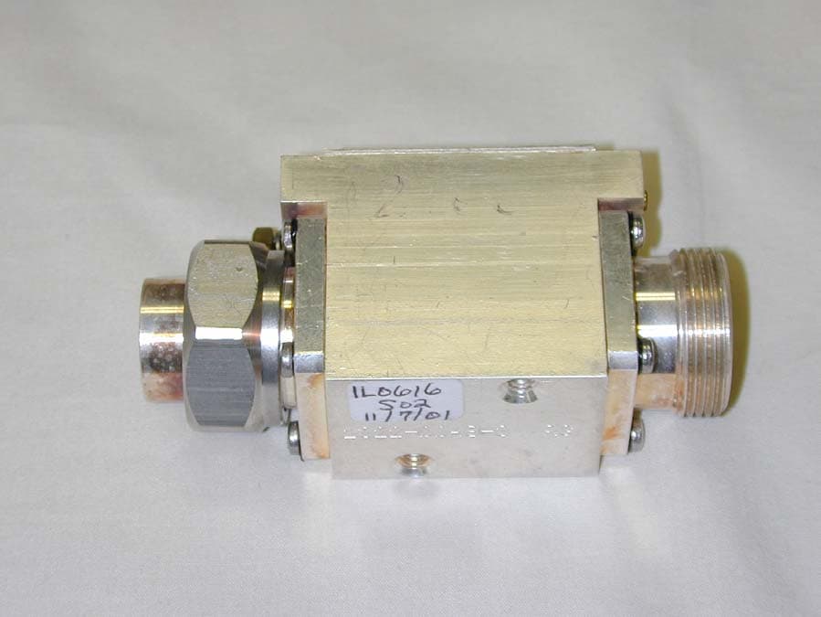
Click to zoom
Application Details
- Equipment Class
- AMP - Amplifier
- Date of Grant
- Apr 07, 2002
- Application Purpose
- Original Equipment
- Date of Application
- Apr 07, 2002
- Equipment Note
- Cellular Band Repeater
- Frequency Range
- 824.00000000 - 849.00000000
- Company
- Powerwave Technologies, Inc.
- Country
- United States
Documents & Files
Document Text
Text extracted from the exhibit documents filed with the FCC. Open a document above to read the original.
Users Manual
G3 MHA INSTALLATION AND OPERATING MANUAL 00/OSM/0002 ISSUE 1 May 2000 REMEC-Airtech G3 Masthead Amplifier Installation and Operating ManualPage 1 of 59 G3 MASTHEAD AMPLIFIER INSTALLATION AND OPERATING MANUAL The information contained in this document is furnished in commercial confidence and upon the condition that the individual and corporate rights originating in the information, whether patented or not, will be respected. Reference: 00/OSM/0002Issue: 1Date: May 2000 Prepared by: Ranjit S Manku Authorised by Engineering:Authorised by Quality: G3 MHA INSTALLATION AND OPERATING MANUAL 00/OSM/0002 ISSUE 1 May 2000 REMEC-Airtech G3 Masthead Amplifier Installation and Operating ManualPage 2 of 59 HISTORY DATEISSUEAUTHOR MOD/ISSUE NOTENOTES 18/05/001Ranjit S MankuECO 1262First Issue G3 MHA INSTALLATION AND OPERATING MANUAL 00/OSM/0002 ISSUE 1 May 2000 REMEC-Airtech G3 Masthead Amplifier Installation and Operating ManualPage 3 of 59 CONTENTS 1Reference....................................................................................................................................................5 1.1System Description.......................................................................................................................5 1.1.1System Operation..............................................................................................................7 1.1.2Interfaces............................................................................................................................9 1.2Hardware Description................................................................................................................20 1.2.1Masthead Amplifier........................................................................................................20 1.2.2Power Distribution Unit.................................................................................................20 1.2.3Bias Tee...........................................................................................................................21 1.2.4Cable Kit...........................................................................................................................21 1.2.5MHA Mounting Kit............................................................................................................21 2Installation Manual.................................................................................................................................22 2.1General.........................................................................................................................................22 1.1.1Recommended RF Cable Installation Components..............................................23 1.1.2Installation Summary and Mounting Configuration.................................................23 1.2Installation of Masthead Amplifier (MHA)...............................................................................26 1.2.1General Mounting Instructions.....................................................................................26 1.1.2Detailed MHA Installation Procedure..........................................................................27 1.1.3Installation of Bias Tee..................................................................................................33 1.1.4Installation of Power Distribution Unit........................................................................33 1.1.5Installation of Cables.....................................................................................................34 2.3Grounding Cables and Lightning Protection.........................................................................34 2.3.1Clamping of cables and correct Grounding..............................................................34 2.3.2Ground Path Requirements.........................................................................................34 2.3.3Grounding/Earthing of the MHA...................................................................................34 2.3.4Schematic of Lightning Protection circuit...................................................................35 2.3.5Basic Grounding/Earthing: Good Practice.................................................................35 2.4Installation Measurements.......................................................................................................36 2.4.1A Method of measurement of Static Gain of the MHA..............................................36 2.4.2Effects of Cable Length on the Noise Figure............................................................37 2.4.3The effects of introducing REMEC-Airtech G3 MHA.................................................37 2.4.4The Effect of Auxiliary attenuator in the Rx path........................................................38 3Operation and Maintenance................................................................................................................40 3.1.1Set-up and Test..............................................................................................................40 3.1.2Fault Finding and Repair Procedures........................................................................40 3.1.3MHA to Ground Equipment DC circuit Test...............................................................42 4Variable Gain MHA Option....................................................................................................................49 4.1Hardware Description................................................................................................................49 4.1.1Variable Gain Masthead Amplifier...............................................................................49 4.1.2Power Distribution Unit.................................................................................................50 4.1.3Bias Tee.................................................................................................................…
Text truncated - open the document above for the full version.
Block Diagram
Block Diagram RX FILTER RX FILTER CURRENT SENSE CIRCUIT BTS DC ANTENNA TX FILTER BIAS TEE
External Photos
External Photos
Internal Photos
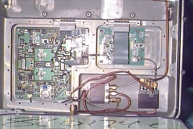
Internal Photos LNA Bottom Left LNA Bottom Right LNA Top Left LNA Top Right LNA Whole
Operational Description
REMEC AIRTECH G20034A1 MASTHEAD AMPLIFIER FUNCTIONAL DESCRIPTION The purpose of the Masthead Preamplifier unit (MHA) is to connect the BTS antenna system to the BTS with the lowest possible noise contribution, the net effect being to optimize BTS receive path sensitivity. A balanced amplifier design is used to provide graceful degradation under component failure. The DC power is supplied to the MHA via a BTS antenna coaxial cable using a Bias Tee. The unit is designed for duplex operation. This technique requires the use of duplex filters or a filter system within the unit to provide a transmit only path and a receive only path through the LNA components. The Masthead Preamplifier is fed with one coaxial cable from the BTS and then connects to the antenna. The Masthead Amplifier shall withstand without damage or performance degradation insertion or removal from the BTS while the BTS is operational.
Parts List/Tune Up Info
PRODUCTION TEST SPECIFICATION G20034A1 15/01/01 ISSUE 1 G20034A1 G3 E-PUMA 850MHz SINGLE FEED MHA FILTER ASSEMBLY TUNE AND TEST This document should be used to tune and check the G3 filter assembly in accordance to Works Instruction WI-07-004. The attached sheet gives tuning instructions and specification limits for the separate filters. This Document Identity Issue Date PTS_G20034A1_Filter 1 15/01/01 Product Code G20034A1 G3 E-Puma Single Feed 850 MHz MHA Tested Against Product Specification Identity Issue Date 01DS0004 1 19/01/01 HISTORY DATE ISSUE AUTHOR ISSUE NOTE CHANGE 15/01/01 01 S. Cox ECO 1807 Original Approved By – Engineering S. Cox Approved By –Quality A. Simmonds Approved By – Production J. Tomlinson PTS_G20034A1_Filter_1.doc PRODUCTION TEST SPECIFICATION G20034A1 15/01/01 ISSUE 1 G3 E-PUMA 850MHz MHA Filter Assembly FILTER TUNING GUIDE (Set markers to Filter Bandwidth) Filter Rx1 Filter Rx2 Filter Tx Information band 824.0 – 849.0 MHz 824.0 – 849.0 MHz 869.0 – 894.0 MHz Filter Centre Frequency 836.5 MHz 836.5 MHz 881.5 MHz Filter bandwidth 822.5 – 850.5 MHz (28 MHz) 822.5 – 850.5 MHz (28 MHz) 867.5 – 895.5 MHz (28 MHz) Return Loss >23 dB >23 dB >23 dB Filter rejection >21 dBc at 815.0 >80 dBc at 868.0 >21 dBc at 815.0 >75 dBc at 868.0 >60 dBc at 850.0 Cross coupling pole 868.5 MHz 868.5 MHz 848.5 MHz FILTER CHARACTERISTICS (checked over Information Band) All parameters must pass specification limits before unit can be stamped as OK and passed to next stage in production. Check all limits after screws have been locked. Para Electrical Parameter Specification Limit Record 5.8 Worst case Tx insertion loss <0.85 dB Write on unit Traveller 5.9 Worst case Tx return loss at BTS port >23 dB 5.10 Worst case Tx return loss at ANT port >23 dB 5.13 Tx to Rx rejection 824-850 MHz >60 dB Write on unit Traveller 5.11 Worst case Rx 1 insertion loss <0.9 dB Write on unit Traveller 5.12 Rx 1 insertion loss variation <0.45 dB Rx1 insertion loss at 815.0 MHz >21.0 dB 5.13 Rx 1 to Tx rejection 868-894 MHz >80 dB Write on unit Traveller 5.14 Worst case Rx1 return loss at ANT port >23 dB 5.15 Worst case Rx1 return loss at Rx1 port >23 dB 5.11 Worst case Rx 2 insertion loss <0.9 dB Write on unit Traveller 5.12 Rx 2 insertion loss variation <0.45 dB Rx2 insertion loss at 815.0 MHz >21.0 dB 5.13 Rx 2 to Tx rejection 868-894 MHz >75 dB Write on unit Traveller 5.14 Worst case Rx2 return loss at BTS port >23 dB 5.15 Worst case Rx2 return loss at Rx2 port >23 dB PTS_G20034A1_Filter_1.doc
Test Report
Nemko Test Report: 1L0616RUS1 Applicant: Remec/Waycom 3238 Southern Drive, Suite 303 Garland, TX 75043 Equipment Under Test: EPUMA EDGE 850 (E.U.T.) In Accordance With: FCC Part 22, Subpart H Cellular Band Repeaters Tested By: Nemko Dallas Inc. 802 N. Kealy Lewisville, TX 75057-3136 Authorized By: Tom Tidwell, Wireless Group Manager Date: 11/14/01 Total Number of Pages: 55 Nemko Dallas FCC PART 22, SUBPART H CELLULAR BAND REPEATERS EQUIPMENT: EPUMA EDGE 850 PROJECT NO.: 1L0616RUS1 Page 2 of 52 Table of Contents SECTION 1. SUMMARY OF TEST RESULTS.............................................................................................3 SECTION 2. GENERAL EQUIPMENT SPECIFICATION..........................................................................5 SECTION 3. RF POWER OUTPUT...............................................................................................................7 SECTION 4. OCCUPIED BANDWIDTH.......................................................................................................8 SECTION 6. FIELD STRENGTH OF SPURIOUS.......................................................................................32 SECTION 7. FREQUENCY STABILITY.....................................................................................................35 SECTION 8. TEST EQUIPMENT LIST.......................................................................................................36 ANNEX A - TEST DETAILS.......................................................................................................................37 ANNEX B - TEST DIAGRAMS...................................................................................................................46 Nemko Dallas FCC PART 22, SUBPART H CELLULAR BAND REPEATERS EQUIPMENT: EPUMA EDGE 850 PROJECT NO.: 1L0616RUS1 Page 3 of 52 Section 1. Summary of Test Results Manufacturer: Remec/Waycom Model No.: EPUMA EDGE 850 Sample No.: S01 General: All measurements are traceable to national standards These tests were conducted on a sample of the equipment for the purpose of demonstrating compliance with FCC Part 22, Subpart H. New Submission Production Unit Class II Permissive Change Pre-Production Unit THIS TEST REPORT RELATES ONLY TO THE ITEM(S) TESTED. THE FOLLOWING DEVIATIONS FROM, ADDITIONS TO, OR EXCLUSIONS FROM THE TEST SPECIFICATIONS HAVE BEEN MADE. See “ Summary of Test Data”. NVLAP LAB CODE: 100426-0 Nemko Dallas Inc. authorizes the above named company to reproduce this report provided it is reproduced in its entirety and for use by the company’s employees only. Any use which a third party makes of this report, or any reliance on or decisions to be made based on it, are the responsibility of such third parties. Nemko Dallas Inc. accepts no responsibility for damages, if any, suffered by any third party as a result of decisions made or actions based on this report. This report applies only to the items tested. Nemko Dallas FCC PART 22, SUBPART H CELLULAR BAND REPEATERS EQUIPMENT: EPUMA EDGE 850 PROJECT NO.: 1L0616RUS1 Page 4 of 52 Summary Of Test Data NAME OF TEST PARA. NO. SPEC. RESULT RF Power Output 22.913(a) 500W ERP Complies Occupied Bandwidth (Voice & SAT) 22.917(c) Mask Complies Occupies Bandwidth (Wideband Data) 22.917(d) Mask Complies Occupied Bandwidth (Digital) 22.917(d) Mask Complies Spurious Emissions at Antenna Terminals 22.917 -13 dBm Complies Field Strength of Spurious Emissions 22.917 -13 dBm E.I.R.P. Complies Frequency Stability 22.355 1.5 ppm N/A Footnotes: The device is an F1-F1 repeater, therefore this parameter was not tested. There is no frequency translation performed within the device. Measurement uncertainty for each test configuration is expressed to 95% probability. . Nemko Dallas FCC PART 22, SUBPART H CELLULAR BAND REPEATERS EQUIPMENT: EPUMA EDGE 850 PROJECT NO.: 1L0616RUS1 Page 5 of 52 Section 2. General Equipment Specification Supply Voltage Input: +12 Vdc Frequency Range: Downlink: 869 – 894 MHz Frequency Range: Uplink: 824 – 849 MHz Note-This repeater has active components for uplink only. CDMA GSM NADC CDPD AMPS (F9W) (GXW) (DXW) (F9W) (F8W, F1D) Type of Modulation and Designator: Output Impedance: 50 ohms Frequency Translation: F1-F1 F1-F2 N/A Software Duplexer Change Fullband Coverage Band Selection: Nemko Dallas FCC PART 22, SUBPART H CELLULAR BAND REPEATERS EQUIPMENT: EPUMA EDGE 850 PROJECT NO.: 1L0616RUS1 Page 6 of 52 Description of Operation The device is a repeater operating in the uplink spectrum of the AMPS band. System Diagram Nemko Dallas FCC PART 22, SUBPART H CELLULAR BAND REPEATERS EQUIPMENT: EPUMA EDGE 850 PROJECT NO.: 1L0616RUS1 Page 7 of 52 Section 3. RF Power Output NAME OF TEST: RF Power Output PARA. NO.: 2.1046 TESTED BY: David Light DATE: 11/8/2001 Test Results: Complies. Test Data: Modulation Type Per Channel Power Output (dBm) Composite Power Output (dBm) Uplink AMPS 22.3 (Single channel) 21.0 (Two [email protected] dBm ea.) Downlink AMPS N/A N/A Uplink CDMA 20.1 (Single channel) 21.7 (Two [email protected] dBm ea.) Downlink CDMA N/A N/A Uplink NADC 21.2 (Single channel) 19.2 (Two [email protected] dBm ea.) Downlink NADC N/A N/A Power output was tested at +/- 10% of nominal with no change in output. Measurement Uncertainty: +/- 0.6 dB Nemko Dallas FCC PART 22, SUBPART H CELLULAR BAND REPEATERS EQUIPMENT: EPUMA EDGE 850 PROJECT NO.: 1L0616RUS1 Page 8 of 52 Section 4. Occupied Bandwidth NAME OF TEST: Occupied Bandwidth PARA. NO.: 2.1049 TESTED BY: David Light DATE: 11/8/2001 Test Results: Complies. Test Data: See attached plots Measurement Uncertainty: +/- 1.7 dB Nemko Dallas FCC PART 22, SUBPART H CELLULAR BAND REPEATERS EQUIPMENT: EPUMA EDGE 850 PROJECT NO.: 1L0616RUS1 Page 9 of 52 Test Data – Occupied Bandwidth Dallas Headquarters: 802 N. Kealy Lewisville, TX 75057 Tel: (972) 436-9600 Fax: (972) 436-2667 Nemko Dallas, Inc. Data Plot Page 1 of4 CompleteX Job No.:1L0616RDate:11/8/2001Preliminary: Specification:PT 22Temperature(°C):22 Tested By:David LightRelativ…
Text truncated - open the document above for the full version.
Test Report
G20034A1 18/07/01 ISSUE 2 PRODUCTION TEST SPECIFICATION G20034A1 G3 E-PUMA 850MHz SINGLE FEED MHA GROUP A TESTS This document should be used to carry out a Group A test in accordance to Works Instruction WI-106. The attached test record sheets are completed for each unit and form the certificate of compliance. This Document Identity Issue Date PTS_G20034A1 2 18/07/01 Product Code G20034A1 G3 E-PUMA 850 MHz Single Feed MHA Tested against Product Specification Identity Issue Date 01DS0004 1 19/01/01 HISTORY DATE ISSUE AUTHOR ISSUE NOTE CHANGE 15/01/01 01 S. Cox ECO 1807 Original Issue 18/07/01 02 S. Cox ECO 2213 Change Spec Limit 86dBm to 84dBm Approved By -Engineering S. Cox Approved By – Quality A. Simmonds Approved By – Production J. Tomlinson PTS_G20034A1_2.doc G20034A1 18/07/01 ISSUE 2 PRODUCTION TEST SPECIFICATION G3 E-PUMA 850MHz SINGLE FEED MHA TEST RECORD SHEET 1 of 1 Product code G20034A1 MHA serial no. ................................................. Wks. Order No. ............................................ LNA serial No. .................................................. TEST FREQUENCIES Rx Frequency Band 824.0 – 849.0 MHz Tx Frequency Band 869.0 – 894.0 MHz It is certified that all tests have been carried out with the following results and are given thus. RF MEASUREMENTS (To WI-106) IMPORTANT – SET SUPPLY VOLTAGE TO 12V Para Description Spec. limit Result (worst case) Tests completed at ambient temperature 22°C ± 2°C 6.1 Return loss at ANT port measured from 823-850 MHz ≥21 dB 6.1 Return loss at BTS port measured from 823-850 MHz ≥21 dB 6.2 Return loss at ANT port measured from 868-895 MHz ≥21 dB 6.2 Return loss at BTS port measured from 868-895 MHz ≥21 dB 6.7 System gain (across Rx band) min. 31.4 dB max. 32.6 dB 6.7 System gain ripple ≤0.9 dB 6.3 Insertion loss across Tx band from BTS to ANT port ≤0.85 dB 6.11 System Noise figure 824 MHz to 849 MHz ≤2.1 dB 6.12 Input 1 dB compression point ≥-7.0 dBm 6.6 Current consumption with supply at +12V ≥400 mA ≤500 mA Test Equipment Nos. ........................................................................................................................... Test Engineer .................................................................. Date ........................................................ PASSIVE INTERMODULATION IN RX INFORMATION BAND (To WI-07-002) Test Carried out with LNA powered 'ON' Tx Carrier 1 869 MHz Tx Carrier 2 894 MHz PIM Order Frequency Measured product 3 844.0 MHz Spec. limit Result Carriers applied to BTS port Reflected PIM product at BTS port -84 dBm Test Engineer ............................................................................. Date ............................................................. PTS_G20034A1_2.doc
Test Setup Photos
Test Set-up Photos Front Side Rear Side
Contact Information
Applicant
Robert Biedka(Sr. Quality Engineer)
Test Firm
Nemko Dallas, Inc.Michael Cantwell
Technical Specifications
| # | Rule Parts | Frequency Range | Power Output | Emission | Tolerance |
|---|---|---|---|---|---|
| 8 | 22H | 824 MHz - 849 MHz | 170.00 mW | F1D | Amp |
Other Applications from Powerwave Technologies, Inc.
OGAS21008
Oct 12, 1999Masthead amplifier enhances performance of PCS, PC
Equipment Class
AMP - Amplifier