OGAS21008Masthead amplifier enhances performance of PCS, PC
Powerwave Technologies, Inc.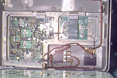
Click to zoom
Application Details
- Equipment Class
- AMP - Amplifier
- Date of Grant
- Oct 12, 1999
- Application Purpose
- Original Equipment
- Date of Application
- Jul 19, 1999
- Equipment Note
- Masthead amplifier enhances performance of PCS, PC
- Frequency Range
- 1930.00000000 - 1990.00000000
- Company
- Powerwave Technologies, Inc.
- Country
- United States
Documents & Files
Document Text
Text extracted from the exhibit documents filed with the FCC. Open a document above to read the original.
Users Manual
INSTALLATION AND OPERATING MANUAL 98/OSM/0019 ISSUE 1 13/04/99 Airtech DCS1800 / PCS1900 Booster System Installation and Operating ManualPage 1 of 25 DCS 1800 / PCS 1900 BOOSTER SYSTEM INSTALLATION AND OPERATING MANUAL The information contained in this document is furnished in commercial confidence and upon the condition that the individual and corporate rights originating in the information, whether patented or not, will be respected. Reference; 98/OSM/0019Issue: 1Date: 13/04/99 Prepared by: Mark Billsberry Authorised by Engineering:Authorised by Quality: INSTALLATION AND OPERATING MANUAL 98/OSM/0019 ISSUE 1 13/04/99 Airtech DCS1800 / PCS1900 Booster System Installation and Operating ManualPage 2 of 25 HISTORY DATEISSUEAUTHOR MOD/ISSUE NOTENOTES 13/04/991Mark BillsberryMI0167Original Issue INSTALLATION AND OPERATING MANUAL 98/OSM/0019 ISSUE 1 13/04/99 Airtech DCS1800 / PCS1900 Booster System Installation and Operating ManualPage 3 of 25 CONTENTS 1.INTRODUCTION4 2.TECHNICAL DESCRIPTION OF BOOSTER SYSTEM EQUIPMENT5 3.INTERFACE DETAILS7 4.INSTALLATION OF THE BOOSTER SYSTEM19 5.COMMISSIONING24 Figure 1 Interface Drawing for the Booster .......................................................................... 7 Figure 2 Interface Drawing for the Booster .......................................................................... 8 Figure 3 Interface Drawing for the Booster External Bias Tee........................................... 10 Figure 4 Interface Drawing for the Variable Gain G3 MHA .............................................. 11 Figure 5 Interface Drawing for the Indoor Variable Gain MHA Bias Tee ......................... 13 Figure 6 Interface Drawing for the Outdoor Variable Gain MHA Bias Tee ...................... 14 Figure 7 Interface Drawing for the PDU with Wall Mounted Bracket ............................... 17 Figure 8 Interface Drawing for the PDU with Pole Mounted Bracket................................ 18 Figure 9 Booster System Connectivity ............................................................................... 23 INSTALLATION AND OPERATING MANUAL 98/OSM/0019 ISSUE 1 13/04/99 Airtech DCS1800 / PCS1900 Booster System Installation and Operating ManualPage 4 of 25 1.Introduction Airtech produce a range of masthead amplifier and associated equipment to provide enhancement of the performance of PCS, PCN, and GSM Base-stations (BTS ). The limitation of the BTS has traditionally been its sensitivity to the Uplink, or received signal at the BTS. The antenna receives the signal from the mobile, but this can be degraded by the feeder cable losses from the antenna down the mast to the BTS. The Airtech Masthead Amplifier employs a low noise amplifier to transmit the improved signal strength down to the BTS overcoming the signal degradation due to the feeder cable losses. The result is a greater sensitivity of the receive system, providing better quality, greater coverage and generally fewer dropped calls, as well as reducing the power required by the mobile phone from any particular location which may increase the battery life and general user satisfaction with the network. The Airtech Booster is designed to increase the downlink signal level by placing the high power amplifiers at the masthead reducing the feeder losses. This extends the range of the base station further, reducing infrastructure costs or improving coverage in black spots. CAUTION: PRIOR TO WORKING ON OR INSTALLING THE BOOSTER SYSTEM OR ANY OF ITS COMPONENTS, ENSURE THAT THE BTS TRANSMITTER RF OUTPUT IS TURNED OFF AND THAT PRECAUTIONS ARE TAKEN TO ENSURE THAT THE TRANSMITTER CANNOT BE ACTIVATED DURING THE EQUIPMENT INSTALLATION. THERE ARE NO USER SERVICABLE COMPONENTS INSIDE THE BOOSTER. RETURN THE UNIT TO THE FACTORY IF SERVICE OR REPAIR IS REQUIRED. INSTALLATION AND OPERATING MANUAL 98/OSM/0019 ISSUE 1 13/04/99 Airtech DCS1800 / PCS1900 Booster System Installation and Operating ManualPage 5 of 25 2.Technical Description of Booster System Equipment The booster system consists of the following units: • Booster • Booster Bias Tee • Variable Gain G3 Masthead Amplifier (Optional) • Variable Gain Masthead Amplifier Compatible Bias Tee (Optional) • Booster System Power Distribution Unit • Connecting Cables 2.1Booster The Booster is designed for masthead operation. It includes a variable gain transmit high power amplifier and a variable high gain LNA. The gain settings are controlled by a micro- controller via a serial data link with the Power Distribution Unit. The Booster is designed to interface with duplexing feeds to both the antenna and the Base Station. The RF, DC power (+30V ) and serial data link are all fed to the booster through the RF coaxial feeder cable. The Booster is housed in a weatherproofed enclosure rated to IP68, with a 7/16 RF connector for the ANT at the top and a 7/16 RF connector for the BTS at the base. There is also a grounding stud mounted on the base used for grounding the Booster to the mast, and provides the discharge path for the lightning protection circuit. 2.2Booster Bias Tee The Booster Bias Tee performs four functions within the booster system. A straight through path is provided for RF signals, the DC power from the PDU is injected onto the feeder and the serial communications to/from the booster is taken from the feeder and supplied to the PDU. The Bias Tee also provides lightning protection for the BTS and PDU. 2.3Variable Gain G3 Masthead Amplifier The Airtech Variable Gain G3 MHA M-series single feeder is designed to deliver up to 22dB Rx gain, low Tx loss and low Rx noise figure in a compact low volume and light weight IP68 enclosure. The MHA-M series single feeder is designed to interface with duplexing feeds to both the antenna and the Base Station. The MHA is housed in a weatherproofed enclosure, with a 7/16 RF connector for the ANT at the top and a 7/16 RF connector for the BTS at the base. There is also a grounding stud mounted on the base used for grounding the MHA …
Text truncated - open the document above for the full version.
ID Label/Location Info
Airtech Part Number: B0 S S A 1850.0 15.0 N/A Serial Number: 000001 FCC ID: OGAS210008 COMPLIES WITH FCC PART 24 and Part 15 of the Rules Example of Booster Label:
ID Label/Location Info
Airtech Part Number: B0 S S A 1850.0 15.0 N/A Serial Number: 000001 FCC ID: OGAS21008 COMPLIES WITH FCC PART 24 and Part 15 of the Rules LABEL LOCATION
Internal Photos
INTERNAL PHOTOS (Page 1 of 6) INTERNAL PHOTOS (Page 2 of 6) INTERNAL PHOTOS (Page 3 of 6) INTERNAL PHOTOS (Page 4 of 6) INTERNAL PHOTOS (Page 5 of 6) INTERNAL PHOTOS (Page 6 of 6)
Operational Description
G\Dev\Ranjit\Booster\Booster_Description COMMERCIAL IN CONFIDENCE 06/08/01 Page 1 of 29 Technical Description Mast Head Booster (PCS1900) and Ancillary Equipment Prepared by Ranjit S Manku 14 th June 99 G\Dev\Ranjit\Booster\Booster_Description COMMERCIAL IN CONFIDENCE 06/08/01 Page 2 of 29 Contents GLOSSARY OF TERMS AND ABBREVIATIONS ....................................................................................................3 1.GENERAL ................................................................................................................................................................3 1.1 S YSTEM..................................................................................................................................................................3 2.SYSTEM DESCRIPTION .......................................................................................................................................4 2.1 GENERAL.............................................................................................................................................................4 3.FUNCTIONAL SPECIFICATION.........................................................................................................................6 3.1 M AST HEAD BOOSTER............................................................................................................................................6 3.2 P OWER DISTRIBUTION UNIT...................................................................................................................................17 3.3 B OOSTER BIAS TEE...............................................................................................................................................19 3.4 C ABLE SET............................................................................................................................................................20 4ELECTRICAL SPECIFICATION .......................................................................................................................21 4.1 M AST HEAD BOOSTER..........................................................................................................................................21 4.2 P OWER DISTRIBUTION UNIT..................................................................................................................................23 4.3 B OOSTER BIAS TEE...............................................................................................................................................27 5MECHANICAL SPECIFICATION .....................................................................................................................28 6ENVIORNMENTAL AND QUALIFICATION SPECIFICATIONS................................................................28 6.1 EMC.....................................................................................................................................................................28 6.2 ENVIRONMENT ................................................................................................................................................28 G\Dev\Ranjit\Booster\Booster_Description COMMERCIAL IN CONFIDENCE 06/08/01 Page 3 of 29 GLOSSARY OF TERMS AND ABBREVIATIONS BTSBase Transceiver Station HPAHigh Power Amplifier LNALow Noise Amplifier MHAMast Head Amplifier MHBMast Head Booster PDUPower Distribution Unit RFRadio Frequency RxReceive TxTransmit VSWRVoltage Standing Wave Ratio SF/SASingle Feeder / Single Antenna DF/DADual Feeder / Dual Antenna 1. GENERAL 1.1System The Masthead Booster System consists of the following: • The Masthead Bi-directional Amplifier or Booster (MHB) including filters, LNA and HPA • The Power Distribution Unit (PDU) to supply DC to MHB and provide system alarms Technical Descriptions of the Mast Head Booster, Power Distribution Unit, Bias Tee and other ancillary equipment is given in this document. The system enables dual duplex operation. The DC Power of the booster (MHB) is supplied via the BTS antenna coaxial feeder cable using Bias Tees. The Mast Head Booster described in this documents is used at the tower top to provide increase in the coverage of the Cellular BTS. This is achieved by providing up to 12dB gain in the Transmitter Path (downlink) and up to 22dB gain in the Receiver Path (uplink). Receive Path The purpose of the low Noise Figure Amplifier in the receive path installed at the tower top close to the antenna is to compensate for all the losses between the antenna and the front end of the BTS receiver and thus improve the BTS sensitivity. The gain of the LNA is remotely adjustable from the PDU via a serial communication interface injected on to the feeder cable through the Bias Tee. G\Dev\Ranjit\Booster\Booster_Description COMMERCIAL IN CONFIDENCE 06/08/01 Page 4 of 29 Transmit Path REMEC-Airtech’s High Power Booster is installed at the tower top to provide a maximum of +43 dBm (20 W) output power at the antenna port thus overcoming any feeder cable losses. The REMEC-Airtech Booster provides up to 12 dB of gain thus allowing very low incoming signals (down to +31 dBm) to provide +43 dBm (20 W) at the antenna input. The gain of the HPA in the MHB is remotely adjustable from the PDU via serial communication interface injected on the feeder cable through the Bias Tee. 2. SYSTEM DESCRIPTION 2.1GENERAL The Booster System is used to compensate for cable loss between the BTS and the antenna and provide extra power on the Transmitter path. The information frequency bandwidth of the Booster system is 15 MHz. The Masthead Booster system consists of the following modules: i) The Masthead Bi-directional Amplifier or Booster (MHB) including filters, LNA and HPA (SF/SA Booster ii) The Power Distribution Unit (PDU) to supply DC to the MHB and provide system alarms iii) The Booster Bias Tee iv) The interface cable kit v) Mounting Kits (MHB, MHA and PDU) A system configuration is shown in the followi…
Text truncated - open the document above for the full version.
Operational Description
Digital Modulation Techniques The Booster provides 12.0 dB of gain to all signals generated by a GSM PCS Base Station. The Base Station generates a digitally modulated signal using a GMSK modulation type. This signal is input into the Booster and then amplified up to a maximum of 20 Watts (+43.0 dBm).
Parts List/Tune Up Info
Procedure for Setting Transmitter Power The HPA attenuator switch sets the transmit gain. The gain will be a maximum 12.0 dB at the “ 0” switch setting. The switches cover an attenuation range of 16.0 dB ( 0 to F in hexadecimal) in 1.0 dB steps. The LNA attenuator sets the receive gain in the booster. The gain will be a maximum of 22.0 dB at the “0” switch setting. The switches cover an attenuation range of 16.0 dB ( 0 to F in hexadecimal) in 1.0 dB steps. The transmit amplifier provides a maximum RF output power of 20 Watts ( +43.0 dBm) and a nominal maximum gain of 12 dB. It is essential that the gain of the booster is adjusted to ensure that the output power does not exceed this level. The following procedure shall be followed: 1. Set the booster transmit attenuation to 16.0 dB by setting the rotary switch on the control panel to F. 2. Enable the BTS Tx carrier output at the required operating power level. 3. While monitoring the booster output power using a suitable power meter, gradually decrease the Tx attenuation until the booster output power reaches the required level (not exceeding 20 W). The booster system is now ready for performance testing.
Parts List/Tune Up Info
PRODUCT SPECIFICATION 98DS0009 Issue 4 April 99 Airtech Product Specification for PCS1900 Booster - Single Feed Single Antenna, Issue 4 Page 1 of 17 EQUIPMENT DESCRIPTION PCS 1900 BOOSTER SINGLE FEED - SINGLE ANTENNA SYSTEM PRODUCT SPECIFICATION The information contained in this document is furnished in commercial confidence and upon the condition that the individual and corporate rights originating in the information, whether patented or not, will be respected. Reference: 98DS0009 Issue: Issue 4.Date: 13 April 1999 Prepared by: Ranjit S Manku & E. Yearby Authorized by Engineering:Authorized by Quality: PRODUCT SPECIFICATION 98DS0009 Issue 4 April 99 Airtech Product Specification for PCS1900 Booster - Single Feed Single Antenna, Issue 4 Page 2 of 17 HISTORY DATEISSUEAUTHOR ISSUE NOTENOTES 03/02/98Issue AR S Manku5000-211 Original 16/03/98Issue 1R S Manku / E. Yearby 5000-260 Changed Title. Technical Specification changed to apply to SF-SA type only. 19Jan99Issue 2R S Manku / E.Yearby 5000-492 Deleted 40 Watt Option. Updated section 2.5 10Mar99Issue 3R S Manku / E.Yearby MI-0115? Added Transmit and Receive Path Output IP3 13Apr99Issue 4R S Manku / E.Yearby MI-0179Called Product Specification. Updated Sections 2.5, 2.9, 3.4,3.6 3.7. Re-introduced HPA bypass as an option. Interface drawings added. PRODUCT SPECIFICATION 98DS0009 Issue 4 April 99 Airtech Product Specification for PCS1900 Booster - Single Feed Single Antenna, Issue 4 Page 3 of 17 CONTENTS 1.TECHNICAL SUMMARY ......................................................................................................... 4 2.ELECTRICAL REQUIREMENTS............................................................................................. 5 3.DC POWER ............................................................................................................................ 8 4.APPROVALS AND REGULATORY ISSUES ......................................................................... 10 5.ENVIRONMENTAL REQUIREMENTS .................................................................................. 11 6.RELIABILITY, MAINTAINABILITY ......................................................................................... 13 7.MECHANICAL REQUIREMENTS.......................................................................................... 13 8.INTERFACES........................................................................................................................ 13 Figure 1 - FUNCTIONAL BLOCK DIAGRAM – WITHOUT Tx BYPASS........................................ 14 Figure 2 - FUNCTIONAL BLOCK DIAGRAM – WITH HPA BYPASS OPTION ............................. 15 Figure 3 - INTERFACE CONTROL DRAWINGS........................................................................... 16 PRODUCT SPECIFICATION 98DS0009 Issue 4 April 99 Airtech Product Specification for PCS1900 Booster - Single Feed Single Antenna, Issue 4 Page 4 of 17 1.TECHNICAL SUMMARY This document defines the system requirements for a Single Feed Single Antenna PCS 1900 Booster. The system consists of a high power amplifier and a bandpass filter in the transmit path and bandpass / lowpass filters and a Low Noise Amplifier in the receive path. The system shall be designed to deliver single carrier Tx nominal gain of 12 dB with a maximum output of +43 dBm (20 W). The nominal gain of Rx shall be 22 dB. The system shall be housed in a compact low volume, lightweight IP68 enclosure. This product is designed to extend coverage, increase traffic and improve the quality of the signal within a network cell. The unit shall be convection cooled. Figure 1 shows a block diagram of a Single Feed Single Antenna (SF-SA) PCS 1900 Booster. This system is connected to the BTS via a common cable for receive and transmit signals, and to a common transmit / receive antenna. As an option, the Booster shall provide a by-pass of the HPA in the transmit section as shown on figure 2, which shall be enabled if the HPA fails. By-pass of the LNA in the receive section shall be a standard configuration, which shall be enabled if the LNA fails The Booster shall be designed to operate over the entire PCS band, but the filters optimized to pass only a 15 MHz band (e.g. A, B, C band). The unit shall be designed to mount on a mast (pole) or a wall and integrated with a customer provided sector antenna. A Solar Shield shall be included to provide protection against direct Sun Radiation. A low pass filter and a variable attenuator at the output of the Low Noise Amplifier shall form an integral part of the LNA tile. The functional status of the LNA shall be monitored, e.g. current drawn by the LNA, and a low loss bypass switch shall be incorporated to provide failure mode operation. An isolator, a VSWR monitoring circuit at the output and a variable attenuator at the input shall form an integral part of the HPA tile. Couplers at the input and the output of the HPA shall be used to monitor the input signal level and the level of the reflected signal at the output port. The Booster shall be designed to ensure good thermal stability. The Booster unit shall also include voltage regulators to provide the required voltage to the amplifiers and to account for any voltage drop across the feeder cables which transmit DC power from the Power Distribution Unit (PDU) at the BTS to the Booster unit. The DC power shall be transmitted via the RF feeder cable using Bias Tees to couple the DC power onto the RF cables. The Bias Tees shall also provide protection against a lightning strike. A serial data interface shall be used to monitor the status of the amplifiers, and display on the PDU at the base. The data interface system may also be used to transmit commands from the BTS to adjust the variable attenuators within the Booster Unit. The serial data signals shall be coupled onto the RF feeder cable via the Bias Tees used for coupling the DC power. The Booster unit shall have 7/16 RF connectors for the antenna and the RF feeder cable …
Text truncated - open the document above for the full version.
Schematics
J1 RF IN RF INPUT MATCHING AMP 1 TRANSISTOR RF OUTPUT MATCHING RF INPUT MATCHING AMP 2 TRANSISTOR RF LINE LOAD 50 OHM RF HYBRID SPLITTER RF INPUT MATCHING RF OUTPUT MATCHING AMP 3, 4 TRANSISTOR LOAD 50 OHM J2 SAMPLE RF OUTPUT FWD POWER DETECTOR J3 RF OUT 5 6 7 8 REVERSE POWER DECTECTOR BIAS ENABLE 1 2 3 4 +24 VDC HPA TEMP SENSOR DC SECTION VCC BIAS GND RF OUT RF IN TRANSISTOR CONFIGURATION Schematic Diagram of High Power Amplifier Description of the High Power Amplifier Assembly The basic operation of the HPA tile used in the REMEC-Airtech Booster is described below. The RF goes in on J1 at a power level of +21.0 dBm it is then amplified by transistor 1 by 8.0 dB approximately. The RF is then routed to transistor 2 and is further amplified by 8.0 dB. The output of amplifier 2 is then equally divided by a hybrid splitter. Each half is then amplified by 7.0 dB by transistor amplifier 3 and 4. Both RF signals are then combined by a hybrid coupler to produce a nominal power of + 44.0 dBm. A sample of RF is provided on J2 ( NOT USED ON REMEC-Airtech Product). There is a forward power detector, which converts a sample of RF to a video voltage which is then routed to the booster control circuitry. There is also an isolator on the output of the HPA which allows RF to pass in and out while providing isolation by dissipating any reflected RF power. The reverse power detector detects reflected power and once again converts it into a video voltage that is then fed to the booster control circuitry. The Bias current enables switches on transistors 1, 2, 3 and 4 allows for correct RF operation and amplification. The RF is provided through SMB J3.
Test Report
KTL Test Report:8L0174EUS Applicant:Airtech Wireless, Inc. 1420 Valwood Pkwy., Suite 200 Carrollton, TX. 75006 Equipment Under Test:PCS 1900 Booster, Single Feed - Single Antenna (E.U.T.) FCC ID:OGAS21008 In Accordance With:FCC Part 24, Subpart E Broadband PCS Repeaters Tested By:KTL Dallas, Inc. 802 N. Kealy Lewisville, TX 75057-3136 Authorized By:_________________________ T. Tidwell, Laboratory Manager Date:03/31/99 Total Number of Pages:51 KTL Dallas, Inc.FCC PART 24, SUBPART E BROADBAND PCS REPEATERS REPORT NO.: 8L0174EUS EQUIPMENT: PCS 1900 Booster, Single Feed - Single Antenna FCC ID: OGAS21008 Page 2 of 41 Table of Contents Section 1. Summary of Test Results ..................................................................................... 4 General Summary of Test Data Section 2. General Equipment Specification........................................................................ 6 Specifications Description of Modifications for Class II Permissive Change Modifications Made During Testing Theory of Operation System Diagram Section 3. RF Power Output................................................................................................ 10 Test Results Test Data Section 4. Occupied Bandwidth .......................................................................................... 12 Occupied Bandwidth (CDMA) Test Results CDMA Input and Output Graphs Occupied Bandwidth (GSM) Test Results GSM Input and Output Graphs Occupied Bandwidth (NADC) Test Results NADC Input and Output Graphs Section 5. Spurious Emissions at Antenna Terminals ...................................................... 25 Test Results Test Data Graphs Section 6. Field Strength of Spurious Radiation ............................................................... 29 Test Results Test Data Test Data - Radiated Emissions - Uplink Test Data - Radiated Emissions - Downlink Photographs of Test Setup KTL Dallas, Inc.FCC PART 24, SUBPART E BROADBAND PCS REPEATERS REPORT NO.: 8L0174EUS EQUIPMENT: PCS 1900 Booster, Single Feed - Single Antenna FCC ID: OGAS21008 Page 3 of 41 Table of Contents (Continued): Section 7. Frequency Stability............................................................................................. 39 Section 8. Test Equipment List ........................................................................................... 40 Annex A - Test Methodologies RF Power Output Occupied Bandwidth (CDMA) Occupied Bandwidth (GSM) Occupied Bandwidth (NADC) Spurious Emission at Antenna Terminals Field Strength of Spurious Frequency Stability Annex B - Test Diagrams R.F. Power Output Occupied Bandwidth Spurious Emissions at Antenna Terminals Field Strength of Spurious Frequency Stability KTL Dallas, Inc.FCC PART 24, SUBPART E BROADBAND PCS REPEATERS REPORT NO.: 8L0174EUS EQUIPMENT: PCS 1900 Booster, Single Feed - Single Antenna FCC ID: OGAS21008 Page 4 of 41 Section 1.Summary of Test Results General: Manufacturer:Airtech Wireless, Inc. Model No.:PCS 1900 Booster, Single Feed - Single Antenna Serial No.:None General:All measurements are traceable to national standards. These tests were conducted on a sample of the equipment for the purpose of demonstrating compliance with FCC Part 24, Subpart E. New SubmissionProduction Unit Class II Permissive ChangePre-Production Unit A M PEquipment Code THIS TEST REPORT RELATES ONLY TO THE ITEM(S) TESTED. THE FOLLOWING DEVIATIONS FROM, ADDITIONS TO, OR EXCLUSIONS FROM THE TEST SPECIFICATIONS HAVE BEEN MADE: NONE. NVLAP LAB CODE: 100351-0 TESTED BY:Ron GaytanDATE:03/29/99 Ron Gaytan, RF Senior Technician KTL Dallas, Inc. authorizes the above named company to reproduce this report provided it is reproduced in its entirety and for use by the company’s employees only. Any use which a third party makes of this report, or any reliance on or decisions to be made based on it, are the responsibility of such third parties. KTL Dallas, Inc. accepts no responsibility for damages, if any, suffered by any third party as a result of decisions made or actions based on this report. This report applies only to the items tested. KTL Dallas, Inc.FCC PART 24, SUBPART E BROADBAND PCS REPEATERS REPORT NO.: 8L0174EUS EQUIPMENT: PCS 1900 Booster, Single Feed - Single Antenna FCC ID: OGAS21008 Page 5 of 41 Summary Of Test Data: NAME OF TESTPARA. NO.SPEC.MEAS.RESULT RF Power Output24.23220W19.9526Complies Occupied Bandwidth (CDMA)24.238Input/OutputSee PlotsComplies Occupied Bandwidth (GSM)24.238Input/OutputSee PlotsComplies Occupied Bandwidth (NADC)24.238Input/OutputSee PlotsComplies Spurious Emissions at Antenna Terminals 24.238(a)-13 dBm-14.1Complies Field Strength of Spurious Emissions24.238(a)-13 dBm E.I.R.P. 58.6Complies Frequency Stability24.235N/A*N/A*N/A* *The E.U.T. is an amplifier; therefore, Frequency Stability is not applicable. Test Conditions: Indoor:Temperature: 24°C Humidity:42% Outdoor:Temperature: 22°C Humidity:40% KTL Dallas, Inc.FCC PART 24, SUBPART E BROADBAND PCS REPEATERS REPORT NO.: 8L0174EUS EQUIPMENT: PCS 1900 Booster, Single Feed - Single Antenna FCC ID: OGAS21008 Page 6 of 41 Section 2.General Equipment Specification Specifications: Supply Voltage Input: 12 V DC Frequency Range: Downlink:1930-1990 MHz Frequency Range: Uplink:1850-1910 (Connected to base station via coaxial cable.) Type of Modulation and CDMAGSMNADC Designator: (F9W)(GXW)(DXW) Output Impedance: 50 Ohms Gain: 2-12 dB Nominal Input Power from BTS: +31 dBm RF Output (Rated): Single:20 Watts Composite:N/A Frequency Translation: F1-F1F1-F2N/A Band Selection: SoftwareDuplexer Change Fullband Coverage KTL Dallas, Inc.FCC PART 24, SUBPART E BROADBAND PCS REPEATERS REPORT NO.: 8L0174EUS EQUIPMENT: PCS 1900 Booster, Single Feed - Single Antenna FCC ID: OGAS21008 Page 7 of 41 Description of Modifications for Class II Permissive Change: KTL Dallas, Inc.FCC PART 24, SUBPART E BROADBAND PCS REPEATERS REPORT NO.: 8L0174EUS EQUIPMENT: PCS 1900 Booster, Single Feed - Single Antenna FCC ID: OGAS21008 Page 8 of 41 …
Text truncated - open the document above for the full version.
Contact Information
Applicant
Robert Biedka(Sr. Quality Engineer)
Technical Contact
KTL Dallas, Inc.Tom Tidwell
[email protected]972/436-9600
802 North Kealy Street · Lewisville, Texas · United States
Non-Technical Contact
KTL Dallas, Inc.John Olivant
[email protected]972/436-9600
Technical Specifications
| # | Rule Parts | Frequency Range | Power Output | Emission | Tolerance |
|---|---|---|---|---|---|
| 2 | 24E | 1.93 GHz - 1.99 GHz | 20 W | DXW | % |
Other Applications from Powerwave Technologies, Inc.
OGAG20034A1
Apr 07, 2002Cellular Band Repeater
Equipment Class
AMP - Amplifier