OGE-QTIMIDSMRLYMRLY � MIDS Single Channel Fixed Frequency Relay
Qual-Tron, Inc.
Click to zoom
Application Details
- Equipment Class
- TNB - Licensed Non-Broadcast Station Transmitter
- Date of Grant
- Feb 19, 2007
- Application Purpose
- Original Equipment
- Date of Application
- Feb 19, 2007
- Equipment Note
- MRLY � MIDS Single Channel Fixed Frequency Relay
- Frequency Range
- 138.00000000 - 174.00000000
- Company
- Qual-Tron, Inc.
- Country
- United States
Documents & Files
Document Text
Text extracted from the exhibit documents filed with the FCC. Open a document above to read the original.
Users Manual
9409 E. 55 th Pl. S. * Tulsa, OK 74145 * (918) 622-7052 * Fax (918) 664-8557 R R E E L L A A Y Y I I N N S S T T R R U U C C T T I I O O N N M M A A N N U U A A L L Relays MRLY and MSRY All rights reserved. No part of this manual may be reproduced or utilized in any form or by any means, electronic or mechanical, without the prior written permission of Qual-Tron, Inc. QTI Page 1 Revision: F Form #: 30Z0136 Effective Date: 23 August 2006 Relay Manual Table of Contents Section 1: MIDS Single Channel Relay (MRLY) Description ........................................................................... Page 3 Features ........................................................................... Page 3 Operation ........................................................................... Page 3 RF Link ........................................................................... Page 3 Emplacement Considerations ........................................................................... Page 3 Section 2: EMIDS Multi-Channel Relay (MSRY) Description ........................................................................... Page 5 Features ........................................................................... Page 5 Operation ........................................................................... Page 6 Setup ........................................................................... Page 6 Data Messages ........................................................................... Page 6 RF Link ........................................................................... Page 6 Emplacement Considerations ........................................................................... Page 7 Battery ........................................................................... Page 7 Section 3: Frequency/Channel Calculations Channel to Frequency .................................................................................... Page 8 Frequency to Channel .................................................................................... Page 8 Section4: FCC Notice / RF Exposure FCC Notice ........................................................................... Page 9 FCC Compliance Information ........................................................................... Page 9 RF Exposure -MPE/SAR ........................................................................... Page 9 QTI Page 2 Revision: F Form #: 30Z0136 Effective Date: 23 August 2006 Section 1: MIDS Single Channel Relay (MRLY) Description The MIDS MRLY is a single channel, fixed frequency relay that receives and re-transmits RF signals from a field of MIDS and EMIDS sensors. This field may be any combination of sensors, such as seismic, magnetic, IR, or break wire. A receiver, transmitter, and control electronics module are encapsulated in the Lexan plastic housing. The repeated signal will be on the same RF frequency as the signal that was received from the original detector. Channel: Factory Pre-Set Single Channel Frequency Range: 138-174 MHz ID Codes: MIDS/EMIDS Antenna: Rod, ½ wave, 3 dB Power Supply: 10 each 9 V DC batteries Battery Life: 45 days in temperate climate. (Optional BPA battery pack – extends life to 120 days) Transmission Output: Minimum 2 Watts Battery Cap Antenna Design Features • Sealed battery compartment • Repeated signal on same frequency • Operational tilt switch • Injection molded Lexan plastic case • Metal battery cap clamps with heat welded metal inserts • Sealed and potted electronic components • Alternate power sources available (BPA Battery Pack Assembly/Solar panel 10-30 Watts) QTI Page 3 Revision: F Form #: 30Z0136 Effective Date: 23 August 2006 A. Operation Install the desired number of batteries and the antenna to make the MRLY operational. The MRLY should be placed between the transmitter and receiver. B. Modes of Operation The MRLY has two modes of operation. These modes are controlled by internal tilt switches. Normal Operation – The MRLY may be put in normal mode by placing it with the antenna up on a flat level location. Power Off – Power is turned off by tilting the unit in any direction past 15°. This mode is used to transport the relay to the development location to prevent transmission and battery power drain. Operational Mode Flat and Level Power Off Mode Tilted past 15°. C. RF Link The operational range of the RF link is dependent upon various conditions. The high frequency of the RF link works best under line of sight conditions. However, operation from gulches and around buildings or hills is possible for shorter ranges. Retransmission ranges of 25 to 100 miles can be achieved. D. Emplacement Considerations The MRLY must be placed within the transmission range of the sensor transmitter assembly. For the best results, place the relay half way between the transmitter and the receiver on a flat surface or at the top of a hill or building. Elevating the repeater antenna or using a toss up antenna will greatly increase the operational range. QTI Page 4 Revision: F Form #: 30Z0136 Effective Date: 23 August 2006 Section 2: EMIDS Multi-Channel Relay (MSRY) Description The EMIDS multi-channel MSRY relay is a self-contained unit that will receive and retransmit RF signals from compatible transmitters. The MSRY relay is programmed using a PC and the supplied software. While programming the unit, the receiver channel, transmit channel, unit ID code, and voltage level from internal batteries are displayed. The unit will transmit a test message when the test button is activated. After programming, the unit may be deployed for operation. An external battery charger may be used to recharge the internal batteries. The MSRY has an external power connector for connection to an external power supply or solar panel. Range Spacing Frequency: Low: 138-154 MHz 25 kHz Mid: 154-162 MHz 5 kHz High: 162-174 MHz 6.25 kHz ID Codes: 0-999 Antenna: Rod, ½ wave, 3 dB Power Supply: 2 each 4 volt gelcell batteries Batt…
Text truncated - open the document above for the full version.
Cover Letter(s)
Jennifer Sanchez From: Samantha Sharbonda Sent: Tuesday, February 06, 2007 6:15 AM To: Chris Harvey Cc: Asad Bajwa; Alex Casadonte; Angela Brown; Jennifer Sanchez; Samantha Sharbonda Subject: Additional Attention needed for Qual-Tron FCC ID:OGE -QTI-MIDSMRLY MT#20331 2/20/2007 Hi Chris, Asad has addressed your initial concerns for this certification. Please see his answers to your questions below. In addition, new photos and a revised report have been added to the customer information folder (H:\METrak_Job_Folders\2006\Q\Qual -Tron , Inc. - QUA14\20331\TCB\Customer Info\MRLY). Please let me know if there is anything else needed to perform the TECH review of this certification. Have a great day! Regards, Samantha Sharbonda TCB Administrator/Documentation MET Laboratories, Inc. Office: 410.949.1918 Fax: 410.354.3313 [email protected] From: Asad Bajwa Sent: Tuesday, February 06, 2007 3:09 AM To: Samantha Sharbonda Subject: RE: Additional Attention needed for Qual-Tron FCC ID:OGE -QTI-MIDSMRLY (?) MT#20331 Hi Sam, The revised report is attached which take care of the template issues. Here is the response to Chris’s questions/comments. The Test Report seems to have many places where FCC 90 Subpart Y (90.1215, FCC 04-265, and more) is referenced, but this is not a 90-Y device. Fixed in report, it is not part Y I can not tell which rule sections actually apply based on the information in the application. The photographs are all out of focus, so I can't tell what I am reviewing. Additional photographs already provided. The frequency range is listed as 138-174 MHz, but the data does not always substantiate this range (much of the data is for 146 - 168MHz). Frequency range is 138-174 MHz, the data provided represents the low mid and high channels tested. Some test report compliance information mentions the EMIDS device which is a different device. Fixed in report, that was a typo. Occupied BW mentions the use of an HP 8546, but this does not show in the equipment list. Fixed in report, that was a typo. The FCC ID’s listed on the Form 731 (both FCC ID field and the equipment code field) do not match the FCC ID listed on the label (different uses of the ‘-‘). Correct FCC ID is OGE-QTIMIDSMRLY Please let me know if I missed any thing or if there is anything else I can help with. In addition I am planning to call Chris in the morning to see if he has any additional comments. Best regards, Asad From: Samantha Sharbonda Sent: Friday, January 26, 2007 9:41 AM To: Asad Bajwa Cc: Jennifer Sanchez; Alex Casadonte; Kevin Mehaffey Subject: FW: Additional Attention needed for Qual-Tron FCC ID:OGE -QTI-MIDSMRLY (?) MT#20331 Hey Asad, Can you please address the below issues that Chris Harvey has come across during the Technical Review for this job? Thanks! -Samantha From: Chris Harvey [mailto:[email protected]] Sent: Friday, January 26, 2007 11:32 AM To: Samantha Sharbonda Cc: Jennifer Sanchez; Kevin Mehaffey; Alex Casadonte; Chris Harvey Subject: Additional Attention needed for Qual-Tron FCC ID:OGE -QTI-MIDSMRLY (?) MT#20331 Sam, I have been trying to make heads-or-tails of this application and need some clarification and correction before I can proceed further in this application. The Test Report seems to have many places where FCC 90 Subpart Y (90.1215, FCC 04-265, and more) is referenced, but this is not a 90-Y device. I can not tell which rule sections actually apply based on the information in the application. The photographs are all out of focus, so I can't tell what I am reviewing. The frequency range is listed as 138-174 MHz, but the data does not always substantiate this range (much of the data is for 146 - 168MHz). The FCC's new policy on frequency ranges for Grants (KDB #634817) is not followed. Some test report compliance information mentions the EMIDS device which is a different device. Occupied BW mentions the use of an HP 8546, but this does not show in the equipment list. The FCC ID’s listed on the Form 731 (both FCC ID field and the equipment code field) do not match the FCC ID listed on the label (different uses of the ‘-‘). Please provide the channelization table for this device (not just LB, MB and HB). Please address the above issues as well as the completeness of the application before resubmitting for review. -----Original Message----- From: Samantha Sharbonda [mailto:[email protected]] Sent: Tuesday, January 23, 2007 2:25 PM To: [email protected] Cc: [email protected]; [email protected]; [email protected]; [email protected]; [email protected] Subject: METrak Mail From: Samantha Sharbonda Importance: High 2/20/2007 Task Number: 301209 Task Description: EMC/TCB Application - MRLY Task Status: In Progress Hi Chris Harvey, Please accomplish technical review for the FCC TCB this project with the following information: H:\METrak_Job_Folders\2006\Q\Qual-Tron , Inc. - QUA14\20331\TCB\Customer Info\MRLY Please keep in mind that our turn around time for technical review is twenty-four to forty-eight hours. Let me know if I should provide you anything else, or if there may be any delays you may foresee in reviewing. Thanks! Regards, Samantha Sharbonda TCB Administrator/Documentation MET Laboratories, Inc. Office: 410.949.1918 Fax: 410.354.3313 2/20/2007
Operational Description
DRN DATE SIZE A CODE IDENT 2N899 DOCUMENT NAME MRLY FCC Operational T echnical.doc REV A CKD DATE The information contained in this document is considered proprietary and is the sole and exclusive property of Qual-Tron, Inc. This information is not to be used except as expressly authorized by this company. TITLE: MRLY – OPERATIONAL TECHNICAL DOCUMENTATION APP DATE SCALE N/A WEIGHT N/A PAGE 1 OF 2 REVISION RECORD LTR DESCRIPTION DATE APPROVED The information contained in this document is considered proprietary and is the sole and exclusive property of Qual-Tron, Inc. TITLE: MRLY OPERATIONAL/ TECHNICAL DESCRIPTION INTRODUCTION Qual-Tron, Inc. of Tulsa Oklahoma manufactures a full range of unattended ground sensors and monitoring systems used to detect intrusion activity. The mechanical and electrical sensors include Breakwire, Magnetic, Seismic, IR Break Beam, Passive IR Sensors and Hydrophones. These sensors are used in combination with the MIDS single channel system, MIDS-II (modified) single channel system and EMIDS Multi-channel system. These systems utilize transmitters, relays and receivers to provide digitally encoded messages of alarm activity. Qual-Tron also manufactures base station equipment, power supplies and auxiliary equipment to provide a complete functional system. PURPOSE The purpose of this document is to provide a brief description of the circuit functions of the MRLY MIDS Single Channel Relay along with a statement describing how the MRLY operates. A description of the ground system and antenna is also discussed. MRLY OPERATIONS The MIDS MRLY is a single channel, fixed frequency relay that receives and re-transmits RF signals from a field of MIDS or EMIDS transmitters. This field may be any combination of sensors, such as seismic, magnetic, IR, or break wire. A receiver, transmitter, and control electronics module are encapsulated in a Lexan plastic housing. CIRCUIT FUNCTIONS BLOCK 1: The receiver is a single channel, low-power, dual conversion FM receiver. The 1 st stage local oscillator is customer specified and factory installed. The receiver consists of an input antenna, a preamp and filter; the first mixer amplifies the signal and converts the RF input to 21.4 MHz. This IF signal is filtered and fed into the second mixer, which further amplifies the signal and converts it to a 455 KHz IF signal by mixing with the 2 nd LO of 20.945 MHz. This signal is fed into a Low pass filter and then into the limiting amplifier and detection circuitry. The audio is recovered using DRN DATE SIZE A CODE IDENT 2N899 DOCUMENT NAME MRLY FCC Operational T echnical.doc REV A CKD DATE The information contained in this document is considered proprietary and is the sole and exclusive property of Qual-Tron, Inc. This information is not to be used except as expressly authorized by this company. TITLE: MRLY – OPERATIONAL TECHNICAL DOCUMENTATION APP DATE SCALE N/A WEIGHT N/A PAGE 2 OF 2 a conventional quadrature detector, converted to digital using a bitslicer circuit and then fed into a microprocessor. BLOCK 2: The microprocessor decodes the received message and then sends the encoded message to the transmitter. The encoded message is a 1200 baud Manchester code that includes 8 bits of preamble, a start bit, the message type, the ID code and the rest of the received message. This encoded message is used to modulate an FSK transmitter. BLOCK 3: The modulation input into the FSK modulator is used to provide deviation for the crystal Y1 +/- 333 Hz. The crystal range of Y1 for the low band is set per customer order in the range 15.333 MHz to 17.00 MHz. This modulated signal is then multiplied using two tripler circuits. This dual tripling multiplies the frequency by 9 to provide a 138 MHz – 154 MHz output with a deviation of +/- 3 KHz. BLOCK 4: The signal is then fed into the RF Power Amp, which is set for 2 watt output. The antenna is a Rod, ½ wave, 3 dB BNC antenna. This antenna is normally used as a receive antenna and is switched to transmit using an RF switch before transmitting the encoded message. The RF switch is enabled by the microprocessor. MODULATION SYSTEM DESCRIPTION The modulation of this system employs Frequency Shift Keying at 1200 Baud. The transmission of data is typically event driven in short-bursts of 25 ms or less. The modulation uses a 20-bit Manchester code that includes 8-bits of preamble, a start bit, 4-bit message type, 6-bits of ID and a parity bit.
Parts List/Tune Up Info
9409 E. 55 th Pl. S. Tulsa, OK 74145-8157 (918) 622-7052 MET Laboratories, Inc. 914 West Patapsco Avenue Baltimore, MD 21230 RE: #18) Tune-up procedure over power range or at specific operating levels. To Whom It May Concern: This is to affirm that the MRLY MIDS Single Channel Fixed Frequency Relay is factory tuned and aligned. The user in-the-field cannot adjust the power of the component. Please contact me if there is any information you may need. Sincerely, Thomas F. Kotch VP Operations August 24, 2006
Test Report
MET Laboratories, Inc. Safety Certification - EMI - Telecom Environmental Simulation 33439 WESTERN AVENUE ! UNION CITY, CALIFORNIA 94587 ! PHONE (510) 489-6300 ! FAX (510) 489-6372 The Nation’s First Licensed Nationally Recognized Testing Laboratory November 1, 2006 Qual-Tron , Inc. 9409 E. 55th Place South Tulsa, OK 74145-8157 Dear Tom Kotch, Enclosed is the EMC test report for compliance testing of the Qual-Tron, Inc., MRLY, tested to the requirements of Title 47 of the Code of Federal Regulations (CFR), Part 90. Thank you for using the services of MET Laboratories, Inc. If you have any questions regarding these results or if MET can be of further service to you, please feel free to contact me. Sincerely yours, MET LABORATORIES, INC. Cheryl Anicete Documentation Department Reference: (Qual-Tron, Inc.\EMCU20331BB-FCC90) Certificates and reports shall not be reproduced except in full, without the written permission of MET Laboratories, Inc. While use of the National Voluntary Laboratory Accreditation Program (NVLAP) letters or the NVLAP Logo, the Standards Council of Canada Logo, A2LA, or the Nationally Recognized Testing Laboratory (NRTL) Letters in this report reflects MET Accreditation under these programs, these letters, logo, or statements do not claim product endorsement by these organizations or any Agency of the U.S. Government. This letter of transmittal is not a part of the attached report. MET Laboratories, Inc. Safety Certification - EMI - Telecom Environmental Simulation 33439 WESTERN AVENUE ! UNION CITY, CALIFORNIA 94587 ! PHONE (510) 489-6300 ! FAX (510) 489-6372 DOC-EMC700 7/9/04 Electromagnetic Compatibility Criteria Test Report For the Qual-Tron, Inc. MRLY FCCID: OGE-QTIMIDSMRLY Tested under The FCC Verification Rules Contained in Title 47 of the CFR, Part 90 for Private Land Mobile Radio Services MET Report: EMCU20331B-FCC90 November 1, 2006 Prepared For: Qual-Tron, Inc. 9409 E. 55th Place South Tulsa, OK 74145-8157 Prepared By: MET Laboratories, Inc. 33439 Western Ave. Union City, California 94587 Electromagnetic Compatibility Qual-Tron , Inc. Certification Label & User’s Manual Information MRLY CFR Title 47, Part 90 MET Report: EMCU20331B-FCC90 © 2007, MET Laboratories, Inc. Page ii of vi DOC-EMC700 7/9/04 Electromagnetic Compatibility Criteria Test Report For the Qual-Tron, Inc. MRLY FCCID: OGE-QTIMIDSMRLY Tested under The FCC Verification Rules Contained in Title 47 of the CFR, Part 90 for Private Land Mobile Radio Services MET Report: EMCU20331B-FCC90 Asad Bajwa Cheryl Anicete Electromagnetic Compatibility Lab Documentation Department Engineering Statement: The measurements shown in this report were made in accordance with the procedures indicated, and the emissions from this equipment were found to be within the limits applicable. I assume full responsibility for the accuracy and completeness of these measurements, and for the qualifications of all persons taking them. It is further stated that upon the basis of the measurements made, the equipment tested is / is not capable of operation in accordance with the requirements of Part 90, of the FCC Rules under normal use and maintenance. Asad Bajwa, Manager Electromagnetic Compatibility Lab Electromagnetic Compatibility Qual-Tron , Inc. Certification Label & User’s Manual Information MRLY CFR Title 47, Part 90 MET Report: EMCU20331B-FCC90 © 2007, MET Laboratories, Inc. Page iii of vi DOC-EMC700 7/9/04 Report Status Sheet Revision Report Date Reason for Revision ∅ November 1, 2006 Initial Issue. Electromagnetic Compatibility Qual-Tron , Inc. Certification Label & User’s Manual Information MRLY CFR Title 47, Part 90 MET Report: EMCU20331B-FCC90 © 2007, MET Laboratories, Inc. Page iv of vi DOC-EMC700 7/9/04 Table of Contents 1. Testing Summary ........................................................................................................................................................ 2 2. Equipment Configuration........................................................................................................................................... 2 2.1. Overview................................................................................................................................................................ 2 2.2. Test Site ................................................................................................................................................................. 2 2.3. Description of Test Sample .................................................................................................................................... 2 2.4. Equipment Configuration....................................................................................................................................... 2 2.5. Support Equipment ................................................................................................................................................ 2 2.6. Ports and Cabling Information ............................................................................................................................... 2 2.7. Mode of Operation ................................................................................................................................................. 2 2.8. Method of Monitoring EUT Operation .................................................................................................................. 2 2.9. Modifications ......................................................................................................................................................... 2 2.9.1. Modifications to EUT ......................................................................................................................... 2 2.9.2. Modifications to Test Standard ........................................................................................................... 2 2.10. Disposition of EUT ............................................…
Text truncated - open the document above for the full version.
Test Setup Photos
Qual-Tron MRLY & MXMT Test Set Up Photographs Qual-Tron MRLY & MXMT
Contact Information
Applicant
Robert H. Kane(President)
Test Firm
MET Laboratories, Inc.Asad Bajwa
Technical Specifications
| # | Rule Parts | Frequency Range | Power Output | Emission | Tolerance |
|---|---|---|---|---|---|
| 1 | 90 | 138 MHz - 174 MHz | 1.9 W | 7K40F1D | 5.0000000000 ppm |
Other Applications from Qual-Tron, Inc.
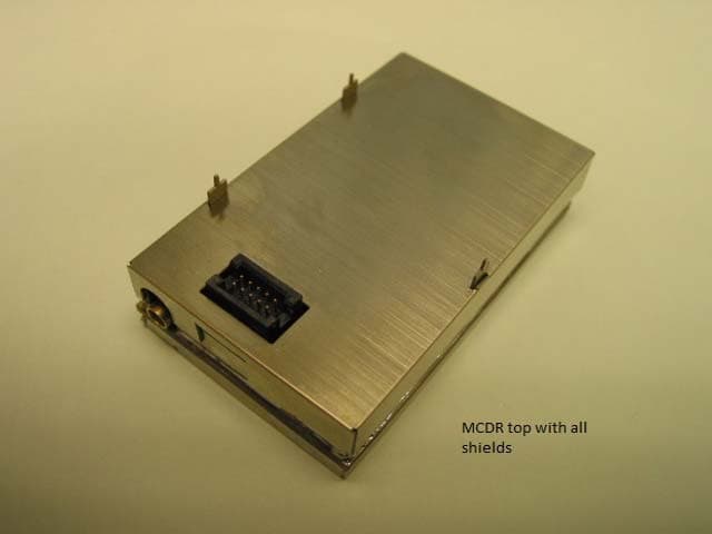
OGEQTIMIDSLBMCDR
Mar 10, 2013MODULAR RECEIVER
Equipment Class
CXX - Communications Rcvr for use w/ licensed Tx and CBs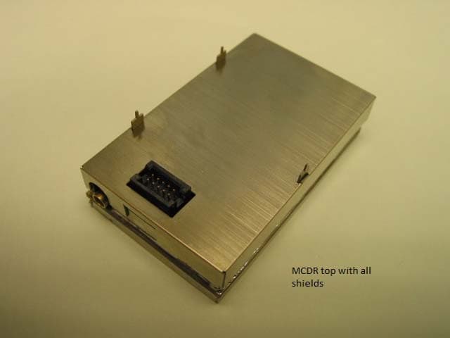
OGEQTIMIDSHBMCDR
Mar 10, 2013MODULAR RECEIVER
Equipment Class
CXX - Communications Rcvr for use w/ licensed Tx and CBs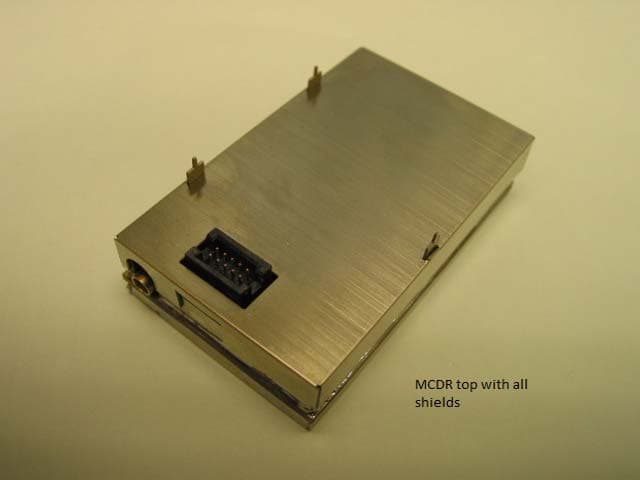
OGEQTIMIDSMBMCDR
Mar 10, 2013MODULAR RECEIVER
Equipment Class
CXX - Communications Rcvr for use w/ licensed Tx and CBs
OGE-QTIMIDSHBMCDT
Jan 20, 2011MCDT TRANSMITTER-HIGH CHANNEL
Equipment Class
TNB - Licensed Non-Broadcast Station Transmitter
OGE-QTIMIDSMBMCDT
Jan 20, 2011MCDT TRANSMITTER
Equipment Class
TNB - Licensed Non-Broadcast Station Transmitter