OHH-BT1000MTBluetooth Headset
Cal-Comp Electronics (Thailand) Co. Ltd.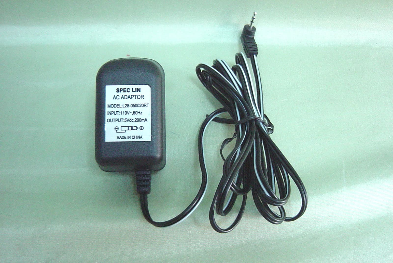
Click to zoom
Application Details
- Equipment Class
- DSS - Part 15 Spread Spectrum Transmitter
- Date of Grant
- Oct 14, 2002
- Application Purpose
- Original Equipment
- Date of Application
- Oct 14, 2002
- Equipment Note
- Bluetooth Headset
- Frequency Range
- 2402.00000000 - 2480.00000000
- Country
- Thailand
Documents & Files
Document Text
Text extracted from the exhibit documents filed with the FCC. Open a document above to read the original.
Users Manual
Cal-Comp 1 Preface Cal-Comp’s Bluetooth TM Headset BT-1000 is a cordless mobile solution built on Bluetooth wireless technology. Please proceed the instructions before using your Headset What is Bluetooth Technology? The Bluetooth wireless Technology eliminates constraint of cables by making connection to any portable and stationary device realized. This is built on the technology that is based on a radio link that provides voice and data transmission. The Bluetooth wireless technology uses a worldwide available range of frequency to ensure communication compatibility throughout the globe. How the Headset is Used? For Headset to work, it must be used with mobile phone, PC or any device with Bluetooth technology that conforms to the Headset Profile. This User’s Guide concentrates on how to use the Headset with your mobile phone. When the Headset is connected to your mobile phone, calls can be made by using voice control (provided that this function is supported by your phone). Because the Headset is designed to keep your hands free, the phone can be tucked away in your pocket or in a bag. By using a three-way button on the Headset, you can easily handle incoming and outgoing calls, and adjust the volume. Cal-Comp 2 Operating Your Headset Overview To be able to use the Headset together with a mobile phone, or any device that you want to use with the Bluetooth Headset, it has to be compatible with Bluetooth wireless technology and supports the Headset Profile. In order to use the Headset with a mobile phone, you need to have a phone with Bluetooth capability built-in. Front Charging connector Indicator light Back Speaker Microphone Ear clip Cal-Comp 3 S1 : On/Off and Answer/End calls S2 : Decrease Volume S3 : Increase Volume Getting Started You should do the following prior to using the Headset with a phone or other device for the first time, z Decide on which ear you want to wear the headset (factory setup is for right-ear use). z Pair the Headset with a device (mobile phone). z Use appropriate Cal-Comp charger to charger the Headset The above stages are described in detail below. Right or Left Ear The direction of the ear clip has to be changed should you decide to wear the Headset on your left ear. To adjust the ear clip for left-ear use: 1. Pull the ear clip from the Headset gently as shown above. Always hold the clip as shown. Cal-Comp 4 2. Turn the clip 180 degrees. 3. Attach the ear clip by gently pressing it into place. You also have to change the orientation of volume button by doing the following: a) Before the Headset flashes green and red, press and hold the Headset button for up to 10 seconds when the Headset is in power off status. b) Slide the volume button in the direction of either upwards or downwards that you want to use to increase the volume. c) Press the Headset button until the Headset is turned off. Putting On the Headset z Press down the lever as shown. z Put on the Headset with the ear clip behind your ear. Cal-Comp 5 z Ensure the microphone is pointing toward your mouth. 3 Turning the Headset On or Off To turn the Headset on z A short low tone will be heard when you press and hold the Headset button, followed by a short high tone. The Headset indicator light now flashes green, and flashes red when low battery is detected. To turn the Headset off z A short high tone will be heard when you press and hold the Headset button followed by a short low tone. The Headset indicator light is now turned off. Pairing the Headset Pairing the Headset with the device you want to use with is required before starting to operate the Headset for the first time. <Reference> To pair with Ericsson’s mobile: Using a Mobile Phone with Built-in Bluetooth Capability. You can simply pair the Headset with your phone by adding it to a list of paired device in the phone. They will connect each other based on the recognition between the phone and the Headset. To pair the Headset with the phone 1. In the phone, scroll the Extras, YES, Bluetooth, YES, Paired devices, YES,ADD device? , YES ,Phone initiates, YES. 2. The phone shows a list of device types that can be paired with it is displayed. Scroll the Headset and press YES. 3. When the Headset is turned off, press and hold the Headset button for up to 10 seconds until the indicator light flashes green and red. Make sure the Headset and the phone are within close proximity. 4. The phone commences searching for the Headset as soon as the Headset passkey Cal-Comp 6 (0000) is entered, and press YES.. 5. When the search is complete, the display shows a list of available devices, like “BT-1000”, then press YES. 6. The preset Headset name may be modified to your own personal name tag now. Press YES. When pairing has been completed, the indicator light on the Headset flashes green. Charging The Headset comes with a rechargeable battery included. The battery is not fully charged when it is new. For first time use, insert the adaptor into the Headset to charge until the indicator light turns green. z It takes 1-1.5hours to fully charge the battery. z To indicate that the Headset runs on low power, the Headset indicator light flashes red when the Headset is on. z When the Headset is turned off during the process of charging, the indicator light shows a steady red light, and flashes red when the Headset is on. z When the headset is turned off once the battery is fully charged, the indicator shows a steady green light, or shows green light if the Headset is on. Which Charger Can I Use Please use Cal-Comp travel charger to the Headset. How to Charge the Battery Cal-Comp 7 . Connect the adaptor into the Headset as shown in the picture. Gently press the adaptor until it clicks into place. Volume Adjustment Listening volume adjustment Headset listening volume can be adjusted during a call. To adjust the listening volume z To turn down the volume, slide the Headset button S2. z To turn up the volume, slide the Headset button S3. Note: The orientation of the volum…
Text truncated - open the document above for the full version.
Cover Letter(s)
Bluetooth Declaration Per FCC 15.247 Requirements 1 Output power and channel separation of a Bluetooth device in the different operating modes: The different operating modes (data-mode, acquisition-mode) of a Bluetooth device don’t influence the output power and the channel spacing. There is only one transmitter which is driven by identical input parameters concerning these two parameters. Only a different hopping sequence will be used. For this reason the check of these RF parameters in one op-mode is sufficient. 2 Frequency range of a Bluetooth device: Hereby we declare that the maximum frequency of this device is: 2402 – 2480 MHz. This is according the Bluetooth Core Specification V 1.0B (+ critical errata) for devices which will be operated in the USA. This was checked during the Bluetooth Qualification tests (Test Case: TRM/CA/04-E). Other frequency ranges ( e.g. for Spain, France, Japan) which are allowed according the Core Specification are not supported by this device. 3 Co-ordination of the hopping sequence in data mode to avoid simultaneous occupancy by multiple transmitters: Bluetooth units which want to communicate with other units must be organized in a structure called piconet. This piconet consist of max. 8 Bluetooth units. One unit is the master the other seven are the slaves. The master co-ordinates frequency occupation in this piconet for all units. As the master hop sequence is derived from it’s BD address which is unique for every Bluetooth device, additional masters intending to establish new piconets will always use different hop sequences. 4 Example of a hopping sequence in data mode: Example of a 79 hopping sequence in data mode: 40, 21, 44, 23, 42, 53, 46, 55, 48, 33, 52, 35, 50, 65, 54, 67, 56, 37, 60, 39, 58, 69, 62, 71, 64, 25, 68, 27, 66, 57, 70, 59, 72, 29, 76, 31, 74, 61, 78, 63, 01, 41, 05, 43, 03, 73, 07, 75, 09, 45, 13, 47, 11, 77, 15, 00, 64, 49, 66, 53, 68, 02, 70, 06, 01, 51, 03, 55, 05, 04 5 Equally average use of frequencies in data mode and behaviour for short transmissions: The generation of the hopping sequence in connection mode depends essentially on two input values: 1. LAP/UAP of the master of the connection 2. Internal master clock The LAP (lower address part) are the 24 LSB’s of the 48 BD_ADDRESS. The BD_ADDRESS is an unambiguous number of every Bluetooth unit. The UAP (upper address part) are the 24 MSB’s of the 48 BD_ADDRESS. The internal clock of a Bluetooth unit is derived from a free running clock which is never adjusted and is never turned off. For synchronisation with other units only offset are used. It has no relation to the time of the day. Its resolution is at least half the RX/TX slot length of 312.5 μs. The clock has a cycle of about one day (23h30). In most case it is implemented as 28 bit counter. For the deriving of the hopping sequence the entire LAP (24 bits), 4 LSB’s (4 bits) (Input 1) and the 27 MSB’s of the clock (Input 2) are used. With this input values different mathematical procedures (permutations, additions, XOR-operations) are performed to generate the sequence. This will be done at the beginning of every new transmission. Regarding short transmissions the Bluetooth system has the following behaviors: The first connection between the two devices is established, a hopping sequence was generated. For transmitting the wanted data the complete hopping sequence was not used. The connection ended. The second connection will be established. A new hopping sequence is generated. Due to the fact that the Bluetooth clock has a different value, because the period between the two transmission is longer (and it cannot be shorter) than the minimum resolution of the clock (312.5 μs). The hopping sequence will always differ from the first one. 6 Receiver input bandwidth and behaviors for repeated single or multiple packets: The input bandwidth of the receiver is 1 MHz. In every connection one Bluetooth device is the master and the other one is the slave. The master determines the hopping sequence (see chapter 5). The slave follows this sequence. Both devices shift between RX and TX time slot according to the clock of the master. Additionally the type of connection (e.g. single or multislot packet) is set up at the beginning of the connection. The master adapts its hopping frequency and its TX/RX timing according to the packet type of the connection. Also the slave of the connection will use these settings. Repeating of a packet has no influence on the hopping sequence. The hopping sequence generated by the master of the connection will be followed in any case. That means, a repeated packet will not be send on the same frequency, it is send on the next frequency of the hopping sequence. 7 Dwell time in data mode The dwell time of 0.3797s within a 30 second period in data mode is independent from the packet type (packet length). The calculation for a 30 second period is a follows: Dwell time = time slot length * hop rate / number of hopping channels *30s Example for a DH1 packet (with a maximum length of one time slot) Dwell time = 625 μs * 1600 1/s / 79 * 30s = 0.3797s (in a 30s period) For multislot packet the hopping is reduced according to the length of the packet. Example for a DH5 packet (with a maximum length of five time slots) Dwell time = 5 * 625 μs * 1600 * 1/5 *1/s / 79 * 30s = 0.3797s (in a 30s period) This is according the Bluetooth Core Specification V 1.0B (+ critical errata) for all Bluetooth devices. There for all Bluetooth devices comply with the FCC dwell time requirement in data mode. This was checked during the Bluetooth Qualification tests. The Dwell time in hybrid mode is measured and stated in the test report. 8 Channel Separation in hybrid mode The nominal channel spacing of the Bluetooth system is 1Mhz independent of the operating mode. The maximum “initial carrier frequency tolerance” which is allowed for Bluetooth is fcenter = 75 kHz. This was checked during the Bluetooth Qualification tests (Test Case:…
Text truncated - open the document above for the full version.
External Photos
C&C Laboratory Co. Ltd. REPORT NO: 020056-RF-ID FCC ID: OHH-BT1000MT DATE: 09/29/2002 APPENDIX 2 EXTERNAL PHOTOGRPHS OF EUT C&C Laboratory Co. Ltd. REPORT NO: 020056-RF-ID FCC ID: OHH-BT1000MT DATE: 09/29/2002 Front View of EUT Back View of EUT C&C Laboratory Co. Ltd. REPORT NO: 020056-RF-ID FCC ID: OHH-BT1000MT DATE: 09/29/2002 Top View of EUT Right View of EUT C&C Laboratory Co. Ltd. REPORT NO: 020056-RF-ID FCC ID: OHH-BT1000MT DATE: 09/29/2002 Adaptor
ID Label/Location Info
FCC ID LABEL FORMAT AND LOCATION Applicant: CAL-COMP ELECTRONICS (THAILAND) PUBLIC CO., LTD., TAIPEI BRANCH FCC ID: OHH-BT1000MT FCC ID: OHH-BT1000MT This device complies with part 15 of the FCC Rules. Operation is subject to the following two conditions: (1) This device may not cause harmful interference, and (2) this device must accept any interference received, including interference that may cause undesired operation. FCC ID LABEL AREA
Internal Photos
C&C Laboratory Co. Ltd. REPORT NO: 020056-RF-ID FCC ID: OHH-BT1000MT DATE: 09/29/2002 APPENDIX 3 INTERNAL PHOTOGRPHS OF EUT C&C Laboratory Co. Ltd. REPORT NO: 020056-RF-ID FCC ID: OHH-BT1000MT DATE: 09/29/2002 Internal of EUT – Open Internal of EUT - Front C&C Laboratory Co. Ltd. REPORT NO: 020056-RF-ID FCC ID: OHH-BT1000MT DATE: 09/29/2002 Internal of EUT - Back
Parts List/Tune Up Info
CAL-COMP ELECTRONICS (THAILAND) PUBLIC COMPANY LIMITED, TAIPEI BRANCH 1 Bluetooth Headset BT1000 ANTENNA TEST REPORT 2002/9/4 Test setup Condition Frequency Ranges : 2.4GHz ~ 2.5GHz Input Power : 0 dBm Impedance Matching : 50 ± 3 VSWR Rate : Less than 2.0 Antenna Gain : 0 dB Test Instrument : HP 8753ET (30kHz ~ 6GHz) Table 1 : Impedance Matching CAL-COMP ELECTRONICS (THAILAND) PUBLIC COMPANY LIMITED, TAIPEI BRANCH 2 Table 2 : VSWR Table 3. antenna position 1 CAL-COMP ELECTRONICS (THAILAND) PUBLIC COMPANY LIMITED, TAIPEI BRANCH 3 Table 4. antenna position 2
Test Report
C&C Laboratory Co. Ltd. REPORT NO: 020056-RF-ID FCC ID: OHH-BT1000MT DATE: 09/29/2002 Page 1 of 55 Rev. 00 ELECTROMAGNETIC EMISSIONS COMPLIANCE REPORT INTENTIONAL RADIATOR CERTIFICATION TO FCC PART 15 SUBPART C REQUIREMENT OF Bluetooth Headset MODEL No.: BT1000 BRAND NAME: CAL-COMP FCC ID: OHH-BT1000MT REPORT NO: 020056-RF-ID ISSUE DATE: Sep. 29, 2002 Prepared for Cal-Comp Electronics (Thailand) Public Co., Ltd. Taipei Branch 9F, 99, Nan-King E. Rd. Section 5, Taipei 105, Taiwan, R.O.C. Prepared by C&C LABORATORY, CO., LTD. #B1, 1 st Fl., Universal Center, No. 183, Sec. 1, Tatung Rd., Hsi Chih, Taipei Hsien, Taiwan, R.O.C. TEL: (02)8642-2071~3 FAX: (02) 8642-2256 C&C Laboratory Co. Ltd. REPORT NO: 020056-RF-ID FCC ID: OHH-BT1000MT DATE: 09/29/2002 Page 2 Rev 00 VERIFICATION OF COMPLIANCE Applicant: Cal-Comp Electronics (Thailand) Public Co., Ltd. Taipei Branch 9F, 99, Nan-King E. Rd. Section 5, Taipei 105, Taiwan, R.O.C. Equipment Under Test: Bluetooth Headset BRAND NAME: CAL-COMP MODEL No.: BT1000 Serial Number: N/A File Number: 020056-RF-ID Date of test: Sep. 20 ~ Sep. 27, 2002 We hereby certify that: The above equipment was tested by C&C Laboratory Co., Ltd. The test data, data evaluation, test procedures, and equipment configurations shown in this report were made in accordance with the procedures given in ANSI C63.4 (1992) and the energy emitted by the sample EUT tested as described in this report is in compliance with conducted and radiated emission limits of FCC Rules Part 15. The test results of this report relate only to the tested sample identified in this report. Approved By Vincent Su / RF Dept. Vice Manager C&C Laboratory Co., Ltd C&C Laboratory Co. Ltd. REPORT NO: 020056-RF-ID FCC ID: OHH-BT1000MT DATE: 09/29/2002 Page 3 Rev 00 Table of Contents 1. GENERAL INFORMATION .........................................................................................................5 1.1 Product Description ............................................................................................................................5 1.2 Related Submittal(s) / Grant (s) ..........................................................................................................5 1.3 Test Methodology ...............................................................................................................................5 1.4 Test Facility.........................................................................................................................................5 1.5 Special Accessories .............................................................................................................................5 1.6 Equipment Modifications....................................................................................................................5 2. SYSTEM TEST CONFIGURATION ............................................................................................6 2.1 EUT Configuration .............................................................................................................................6 2.2 EUT Exercise ......................................................................................................................................6 2.3 Test Procedure.....................................................................................................................................6 2.4 Configuration of Tested System..........................................................................................................7 3. SUMMARY OF TEST RESULTS .................................................................................................9 4. DESCRIPTION OF TEST MODES ..............................................................................................9 5. CONDUCTED EMISSION TEST................................................................................................10 5.1 Standard Applicable ..........................................................................................................................10 5.2 EUT Setup.........................................................................................................................................10 5.3 Measurement Procedure....................................................................................................................10 5.4 Measurement Equipment Used: ........................................................................................................11 5.5 Measurement Result..........................................................................................................................11 6. PEAK OUTPUT POWER MEASUREMENT............................................................................18 6.1 Standard Applicable ..........................................................................................................................18 6.2 Measurement Procedure....................................................................................................................18 Measurement Result..........................................................................................................................18 6.4 Measurement Equipment Used: ........................................................................................................18 7. 20dB BAND WIDTH .....................................................................................................................19 7.1 Standard Applicable ..........................................................................................................................19 7.2 Measurement Procedure....................................................................................................................19 Measurement Result..........................................................................................................................19 7.4 Measurement Equipment Used: ..............................................................…
Text truncated - open the document above for the full version.
Test Setup Photos
C&C Laboratory Co. Ltd. REPORT NO: 020056-RF-ID FCC ID: OHH-BT1000MT DATE: 09/29/2002 APPENDIX 1 PHOTOGRPHS OF SET UP C&C Laboratory Co. Ltd. REPORT NO: 020056-RF-ID FCC ID: OHH-BT1000MT DATE: 09/29/2002 Radiated Emission Set up Photos C&C Laboratory Co. Ltd. REPORT NO: 020056-RF-ID FCC ID: OHH-BT1000MT DATE: 09/29/2002 Conducted Emission Set Up Photos
Contact Information
Applicant
Jeffrey Hsu(Product Manager)
Test Firm
Compliance Certification Services Inc.Kurt Chen
Technical Specifications
| # | Rule Parts | Frequency Range | Power Output |
|---|---|---|---|
| 1 | 15C | 2.40 GHz - 2.48 GHz | 1.00 mW |
Other Applications from Cal-Comp Electronics (Thailand) Co. Ltd.
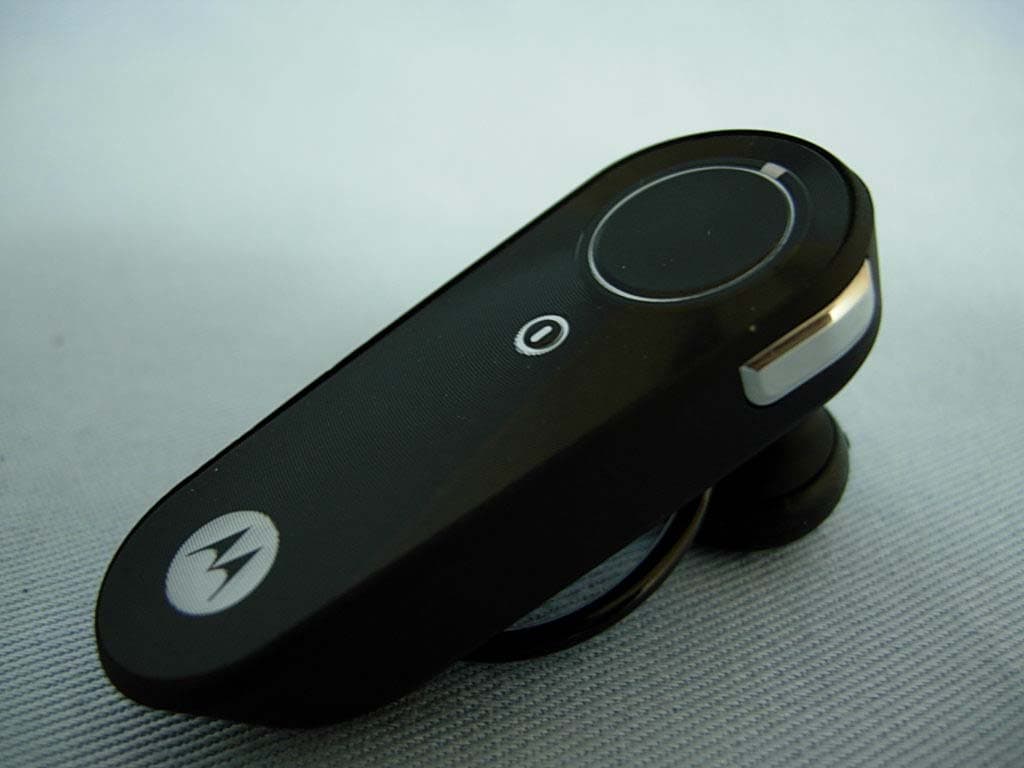
OHH-H371M
Oct 31, 2007BLUETOOTH HEADSET
Equipment Class
DSS - Part 15 Spread Spectrum Transmitter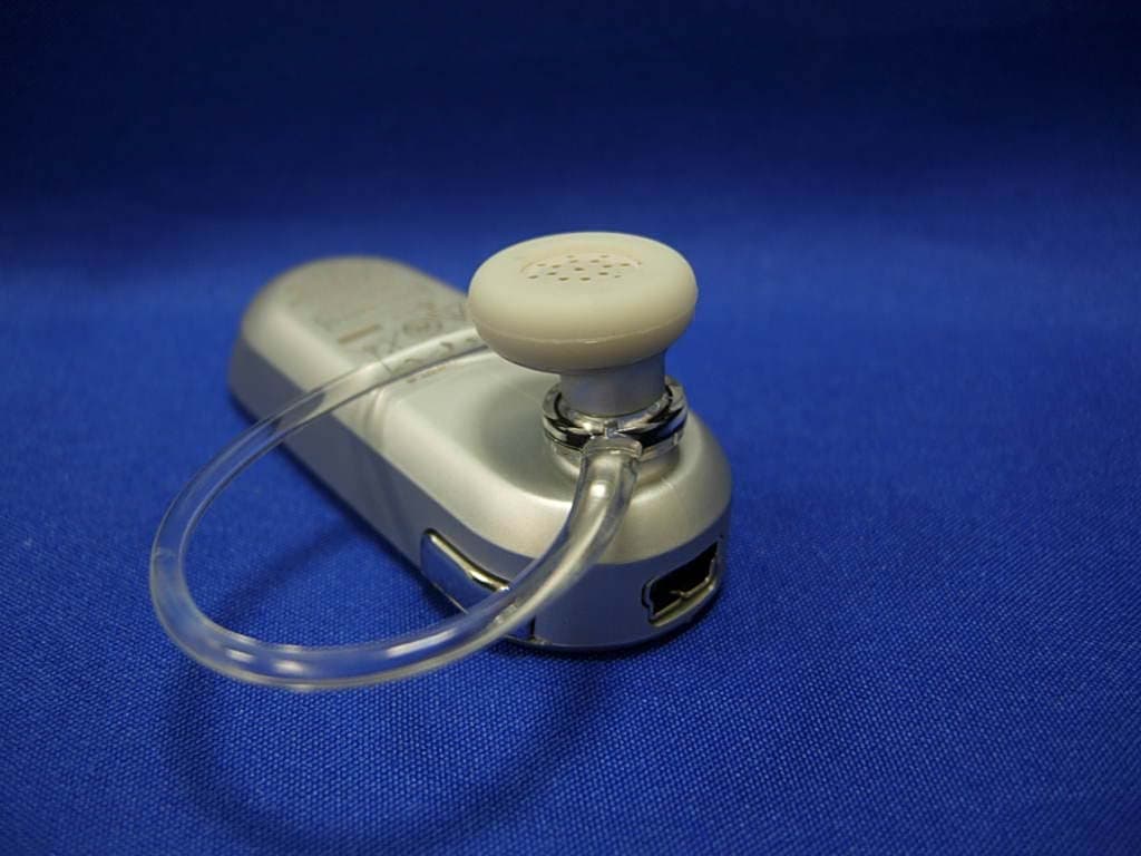
OHH-H385M
Oct 24, 2007BLUETOOTH HEADSET
Equipment Class
DSS - Part 15 Spread Spectrum Transmitter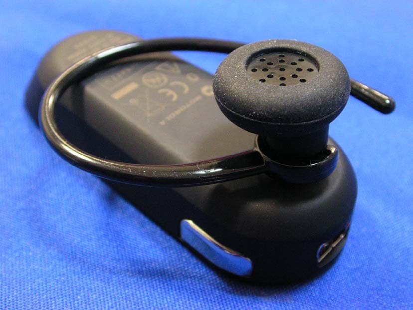
OHH-H385H
Sep 12, 2007Bluetooth Headset
Equipment Class
DSS - Part 15 Spread Spectrum Transmitter
OHH-H371H
Sep 12, 2007Bluetooth Headset
Equipment Class
DSS - Part 15 Spread Spectrum Transmitter
OHH-H375M
Jul 24, 2007BLUETOOTH HEADSET
Equipment Class
DSS - Part 15 Spread Spectrum Transmitter