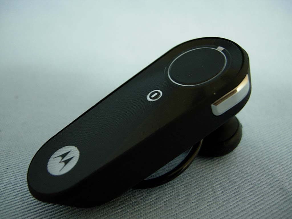
OHH-H371HBluetooth Headset
Cal-Comp Electronics (Thailand) Co. Ltd.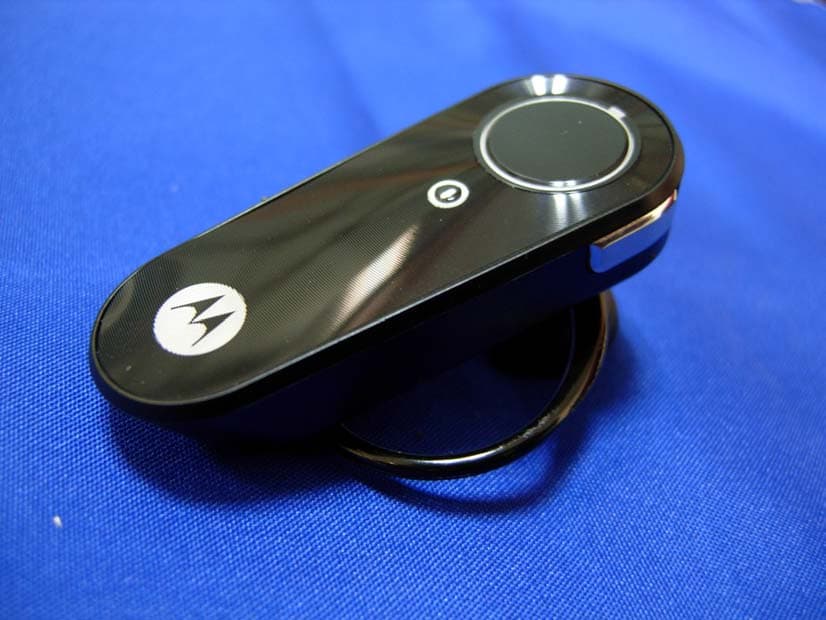
Click to zoom
Application Details
- Equipment Class
- DSS - Part 15 Spread Spectrum Transmitter
- Date of Grant
- Sep 12, 2007
- Application Purpose
- Original Equipment
- Date of Application
- Sep 12, 2007
- Equipment Note
- Bluetooth Headset
- Frequency Range
- 2402.00000000 - 2480.00000000
- Country
- Thailand
Documents & Files
Document Text
Text extracted from the exhibit documents filed with the FCC. Open a document above to read the original.
Users Manual
Power Button Volume Buttons Indicator Light IMPORTANT: Be sure to first follow the Quick Start Guide on the reverse side of this guide to complete initial setup of your H220. Features and Functions Guide H220 Bluetooth® Handsfree Headset TURNING HEADSET ON AND OFF CHANGING VOLUME BUTTON ORIENTATION You can also change the orientation of the volume buttons on your headset. Turn the headset power off. Press and hold both the Volume button you want to assign as the "volume up" button and the Power button to power on the headset. The indicator light flashes three times in blue. 1 2 • The essential requirements and other relevant provisions of Directive 1999/5/EC. • All other relevant EU Directives. European Union Directives Conformance Statement Product Approval Number The above gives an example of a typical Product Approval Number. You can view your product’s Declaration of Conformity (DoC) to Directive 1999/5/EC (to R&TTE Directive) at www.motorola.com/rtte. To find your DoC, enter the product Approval Number from your product’s label in the “Search” bar on the web site. Hereby, Motorola declares that this product is in compliance with: MAKING CALLS Function Action Make a voice dial call Tap the Call button and speak the name after the tone End a call Tap the Call button Answer a call Tap the Call button Ignore a call Press and hold either Volume button until incoming call stops ringing Redial last call Press and hold the Call button for at least 2 seconds until you hear a beep Mute or unmute a call Tap both Volume buttons Note: Some features are phone/network dependent. Note: Your H220 supports both Handsfree and Headset Profiles. Accessing call functions depends upon which profile your phone supports. See your phone's user's guide for more information. AUDIO TONES Audio Tone Headset Status Ascending tone Powering on Descending tone Powering off Two ascending Pairing successful/ tones Initiate voice dial Ring tone Incoming call Two short tones when Volume at minimum pressing Volume button or maximum High/low tones Low battery repeated every 60 sec. No audio indications; Out of range deteriorating quality Three ascending tones Connected call Three descending tones Ended call Two rapid ascending Mute enabled tones Two rapid descending Mute disabled tones WEARING THE HEADSET INDICATOR LIGHT With No Charger Plugged In Headset Indicator Headset Status Off Power off Three blue flashes Powering on/off Steady blue Pairing mode Rapid blue/purple flashes Pairing successful Quick blue flash Incoming/outgoing call Slow blue pulse Connected (on a call) Slow blue flash Standby (not on a call) Slow red flash Idle (not connected to phone) Slow purple pulse Connected call muted Quick red flash Low battery Note: After 30 minutes on a call or of inactivity, the light stops flashing to conserve power, but the headset remains on. Note: To disable the indicator light, press and hold both Volume buttons while powering on the headset. With the Charger Plugged In Headset Indicator Headset Status Red Charging (battery level less than 10% charge) Purple Charging (battery level more than 10% charge) Blue Charging complete When Checking Battery Level Headset Indicator Headset Status Red Battery at less than 10% charge Purple Battery at between 10% and 80% charge Blue Battery at more than 80% charge To turn your headset on, press and hold the Power button until the indicator light flashes. To turn your headset off, press and hold the Power button until the indicator light flashes rapidly and then turns off. CHANGING FOR USE ON OTHER EAR Gently lift and pull the top of the earhook up and off speaker stem. Flip the headset over. Gently attach the earhook to the speaker stem. 1 2 3 3 You can wear your H220 headset on your left or right ear. The headset comes ready for the right ear. To change the headset for the left ear: INDICATOR LIGHT While turned on and not on a call, you can check your headset’s battery charge level by pressing and holding both Volume buttons until you hear a beep (about 5 seconds) The indicator light displays charge status for a few seconds (see “Indicator Light” below for details). To wear your headset, flex the earhook and loop it over your ear as shown. Your H220 headset is supplied with multiple earbuds. The earbud is fitted onto the end of your headset’s earpiece speaker, and placed onto your ear when using your headset as shown. DRAFT DRAFT motorola.com Important Safety and Legal Information > 2 Motorola, Inc. Consumer Advocacy Office 1307 East Algonquin Road Schaumburg, IL 60196 www.hellomoto.com 1-800-331-6456 (United States) 1-888-390-6456 (TTY/TDD United States for hearing impaired) 1-800-461-4575 (Canada) The use of wireless devices and their accessories may be prohibited or restricted in certain areas. Always obey the laws and regulations on the use of these products. MOTOROLA and the Stylized M Logo are registered in the US Patent & Trademark Office. All other product or service names are the property of their respective owners. © Motorola, Inc., 2005. Manual Number: 6809494A55-O 3 The information contained in Motorola's user's guides is believed to be correct at the time of printing. Motorola reserves the right to change or modify any information or specifications without notice. The contents of Motorola’s user manuals are provided “as is.” Except as required by applicable law, no warranties of any kind, either express or implied, including, but not limited to, the implied warranties of merchantability and fitness for a particular purpose, are made in relation to the accuracy, reliability, or contents of this document. Software Copyright Notice The Motorola products described in this manual may include copyrighted Motorola and third-party software stored in semiconductor memories or other media. Laws in the United States and other countries preserve for Motorola and third-party software providers certain exclusive rights for copyrighted software, such as the exclusive rights to distri…
Text truncated - open the document above for the full version.
Attestation Statements
Cal-Comp Electronics (Thailand) Co. Ltd. FCC ID.: OHH-H371H 191/54,57, 18th FL., Rachadapisek Rd., Klongtoey, Bangkok, Thailand. Tel : 886-2-8913-2001#7741 Federal Communications Commission Sep. 04 , 2007 Authorization and Evaluation Division ATTESTATION FCC ID: OHH-H371H Product: Bluetooth Headset Model: H371 We don't provide any controls or software to allow operation outside the USA frequency band when we sell this product in USA. Sincerely, Johnhl / Engineer . Cal-Comp Electronics (Thailand) Co. Ltd.
Cover Letter(s)
RF_160, Issue 01 Declaration of Authorization We Name: MOTOROLA INC. Address: 600 North US Highway 45, Libertyville, lIIionis 60048, USA City: .................................................................. . Country: Canada .................................................................. . Declare that: Name: QuieTek Corp. Address: Fl.2, No.345, Xin-hu 2 nd Rd., Nei-hu District City: Taipei Country Taiwan is authorized to apply for Certification of the following product(s): Product description: Bluetooth Headset ........................... . Type designation: H371 .......................................... . Trademark: MOTOROLA .................................... . on our behalf. Date: ... 2007/09/04 ............... .. City: ... Canada ............... .. Name: ... Nicketta Charles ............ .. Signature:
Cover Letter(s)
Cal-Comp Electronics (Thailand) Co. Ltd. FCC ID.: OHH-H371H 191/54,57, 18th FL., Rachadapisek Rd., Klongtoey, Bangkok, Thailand Tel : 886-2-8913-2001#7741 Cal-Comp Electronics (Thailand) Co. Ltd. 191/54,57, 18th FL., Rachadapisek Rd., Klongtoey, Bangkok, Thailand Tel : 886-2-8913-2001#7741 Fax: 886-2-8913-2001 Federal Communications Commission Sep. 04 , 2007 Authorization and Evaluation Division Confidentiality Request Pursuant to Sections 0.457 and 0.459 of the Commission’s Rules, the Applicant Hereby requests confidential treatment of information accompanying this Application As outlined below: Block diagram: (H371) BlkDia Scheme: (H371) Schem The above materials contain trade secrets and proprietary information not customarily Released to the public. The public disclosure of these matters might be harmful to the Applicant and provide unjustified benefits to its competitors. The Applicant understands that pursuant to Rule 0.457, disclosure of this Application and all accompanying documentation will not be made before the date of the Grant for this application. Sincerely, Johnhl / Engineer . Cal-Comp Electronics (Thailand) Co. Ltd.
External Photos
Report No.: 079025R-RFUSP06V01 Page : 1 of 11 Version:1.0 Attachment 2 : EUT Detailed Photographs (1) EUT Photo (2) EUT Photo
ID Label/Location Info
Cal-Comp Electronics (Thailand) Co. Ltd. FCC ID.: OHH-H371H 191/54,57, 18th FL., Rachadapisek Rd., Klongtoey, Bangkok, Thailand. Tel : 886-2-8913-2001#7741 FCC ID Label The FCC ID will be placed on the equipment as shown in the photograph below.
Internal Photos
Report No.: 079025R-RFUSP06V01 Page : 2 of 11 Version:1.0 (3) EUT Photo (4) EUT Photo Report No.: 079025R-RFUSP06V01 Page : 3 of 11 Version:1.0 (5) EUT Photo (6) EUT Photo Report No.: 079025R-RFUSP06V01 Page : 4 of 11 Version:1.0 (7) EUT Photo (8) EUT Photo Report No.: 079025R-RFUSP06V01 Page : 5 of 11 Version:1.0 (9) EUT Photo (10) EUT Photo Report No.: 079025R-RFUSP06V01 Page : 6 of 11 Version:1.0 (11) EUT Photo (12) EUT Photo Report No.: 079025R-RFUSP06V01 Page : 7 of 11 Version:1.0 (13) EUT Photo (14) EUT Photo Report No.: 079025R-RFUSP06V01 Page : 8 of 11 Version:1.0 (15) EUT Photo (16) EUT Photo Report No.: 079025R-RFUSP06V01 Page : 9 of 11 Version:1.0 (17) EUT Photo (18) EUT Photo Report No.: 079025R-RFUSP06V01 Page : 10 of 11 Version:1.0 (19) EUT Photo (20) EUT Photo Report No.: 079025R-RFUSP06V01 Page : 11 of 11 Version:1.0 (21) EUT Photo
Operational Description
Report No. 079025R-RFUSP06V01 Page: 8 of 50 Version:1.0 1.2. Operational Description The EUT is an Bluetooth Headset with a built-in 2.4GHz Bluetooth transceiver. The number of the channels is 79 in 2402-2480MHz. The device adapts the frequency hopping spread spectrum modulation. The antenna is connector-type and provides diversity function to improve the receiving function. This device provides wireless technology that revolutionizes personal connectivity. It is the solution for the seamless integration of Bluetooth technology into personal computer enabling short-range wireless connections between desktop/laptop computers, Bluetooth-enabled peripherals, and portable handheld devices.
RF Exposure Info
Report No. 079025R-RFUSP06V01 Page: 1 of 3 Version: 1.0 RF Exposure Evaluation declaration Product Name : Bluetooth Headset Model No. : H371 FCC ID OHH-H371H Applicant : Cal-Comp Electronics (Thailand) Co. Ltd. Address : 191/54,57, 18th FL., Rachadapisek Rd., Klongtoey, Bangkok, Thailand Date of Receipt : May 22, 2007 Date of Declaration: Aug. 30, 2007 Report No. : 079025R-RFUSP06V01 The declaration results relate only to the samples calculated. The declaration shall not be reproduced except in full without the written approval of QuieTek Corporation. This report must not be used to claim product endorsement by NVLAP any agency of the U.S. Government Report No. 079025R-RFUSP06V01 Page: 2 of 3 Version: 1.0 1. RF Exposure Evaluation 1.1. Limits According to FCC 1.1310: The criteria listed in the following table shall be used to evaluate the environment impact of human exposure to radio frequency (RF) radiation as specified in 1.1307(b) LIMITS FOR MAXIMUM PERMISSIBLE EXPOSURE (MPE) Frequency Range (MHz) Electric Field Strength (V/m) Magnetic Field Strength (A/m) Power Density (mW/cm 2 ) Average Time (Minutes) (A) Limits for Occupational/ Control Exposures 300-1500 -- -- F/300 6 1500-100,000 -- -- 5 6 (B) Limits for General Population/ Uncontrolled Exposures 300-1500 -- -- F/1500 6 1500-100,000 -- -- 1 30 F= Frequency in MHz Friis Formula Friis transmission formula: Pd = (Pout*G)/(4*pi*r 2 ) Where Pd = power density in mW/cm 2 Pout = output power to antenna in mW G = gain of antenna in linear scale Pi = 3.1416 R = distance between observation point and center of the radiator in cm Pd id the limit of MPE, 1 mW/cm 2 . If we know the maximum gain of the antenna and the total power input to the antenna, through the calculation, we will know the distance r where the MPE limit is reached. 1.2. Test Procedure Software provided by client enabled the EUT to transmit and receive data at lowest, middle and highest channel individually. The temperature and related humidity: 18°Cand 78% RH. Report No. 079025R-RFUSP06V01 Page: 3 of 3 Version: 1.0 1.3. Test Result of RF Exposure Evaluation Product : Bluetooth Headset Test Item : RF Exposure Evaluation Test Site : CTR1 Antenna Gain Antenna Gain: The maximum Gain measured in fully anechoic chamber is 2.37dBi in logarithm scale. Output Power Into Antenna & RF Exposure Evaluation Distance (2.37dBi): Channel Frequency (MHz) Output Power to Antenna (mW) Power Density at R = 2.5 cm (mW/cm2) 00 2402.00 2.3442 0.0515 39 2441.00 2.9854 0.0656 78 2480.00 3.1189 0.0685 The distance r (4 th column) calculated from the Fries transmission formula is far shorter than 2.5 cm separation requirement.
Test Report
Report No. 079025R-RFUSP06V01 Page: 1 of 50 Version:1.0 Test Report Product Name Bluetooth Headset Model No. H371 FCC ID. OHH-H371H Applicant Cal-Comp Electronics (Thailand) Co. Ltd. Address 191/54,57, 18th FL., Rachadapisek Rd., Klongtoey, Bangkok, Thailand Date of Receipt May 22, 2007 Issued Date Aug. 30, 2007 Report No. 079025R-RFUSP06V01 The Test Results relate only to the samples tested. The test report shall not be reproduced except in full without the written approval of QuieTek Corporation. This report must not be used to claim product endorsement by NVLAP any agency of the U.S. Government Report No. 079025R-RFUSP06V01 Page: 2 of 50 Version:1.0 Test Report Certification Issued Date: Aug. 30, 2007 Report No.: 079025R-RFUSP06V01 Product Name Bluetooth Headset Applicant Cal-Comp Electronics (Thailand) Co. Ltd. Address 191/54,57, 18th FL., Rachadapisek Rd., Klongtoey, Bangkok, Thailand Manufacturer Cal-Comp Electronics (Thailand) Co. Ltd. Model No. H371 FCC ID. OHH-H371H Rated Voltage AC 120V/60Hz Working Voltage DC 3.8V Trade Name MOTOROLA Applicable Standard FCC CFR Title 47 Part 15 Subpart C: 2006 ANSI C63.4: 2003 Test Result Complied The Test Results relate only to the samples tested. The test report shall not be reproduced except in full without the written approval of QuieTek Corporation. This report must not be used to claim product endorsement by NVLAP any agency of the U.S. Government Documented By : ( Engineering Adm. Specialist / Genie Chang ) Tested By : ( Engineer / Dino Chen ) Approved By : ( Deputy Manager / Vincent Lin ) 0914 Report No. 079025R-RFUSP06V01 Page: 3 of 50 Version:1.0 TABLE OF CONTENTS Description Page 1. GENERAL INFORMATION ...............................................................................................................5 1.1. EUT Description......................................................................................................................................5 1.2. Operational Description...........................................................................................................................7 1.3. Tested System Details..............................................................................................................................8 1.4. Configuration of Tested System ..............................................................................................................8 1.5. EUT Exercise Software ...........................................................................................................................8 1.6. Test Facility .............................................................................................................................................9 2. CONDUCTED EMISSION ................................................................................................................10 2.1. Test Equipment ......................................................................................................................................10 2.2. Test Setup ..............................................................................................................................................10 2.3. Limits.....................................................................................................................................................11 2.4. Test Procedure .......................................................................................................................................11 2.5. Uncertainty ............................................................................................................................................11 2.6. Test Result of Conducted Emission .......................................................................................................12 3. PEAK POWER OUTPUT ..................................................................................................................18 3.1. Test Equipment ......................................................................................................................................18 3.2. Test Setup ..............................................................................................................................................18 3.3. Limit .....................................................................................................................................................18 3.4. Uncertainty ............................................................................................................................................18 3.5. Test Result of Peak Power Output .........................................................................................................19 4. RADIATED EMISSION .....................................................................................................................20 4.1. Test Equipment ......................................................................................................................................20 4.2. Test Setup ..............................................................................................................................................21 4.3. Limits.....................................................................................................................................................21 4.4. Test Procedure .......................................................................................................................................22 4.5. Uncertainty ............................................................................................................................................22 4.6. Test Result of Radiated Emission ..........................................................................................................23 5. BAND EDGE .......................................................................................................................................30 5.1. Test Equipment ............…
Text truncated - open the document above for the full version.
Test Setup Photos
Report No.: 079025R-RFUSP06V01 Page : 1 of 5 Version:1.0 Attachment 1: EUT Test Setup Photographs Front View of Conducted Test-Mode 2 Back View of Conducted Test-Mode 2 Report No.: 079025R-RFUSP06V01 Page : 2 of 5 Version:1.0 Front View of Conducted Test-Mode 3 Back View of Conducted Test- Mode 3 Report No.: 079025R-RFUSP06V01 Page : 3 of 5 Version:1.0 Front View of Conducted Test-Mode 4 Back View of Conducted Test- Mode 4 Report No.: 079025R-RFUSP06V01 Page : 4 of 5 Version:1.0 Front View of Radiated Test (Horn) Back View of Radiated Test (Horn) Report No.: 079025R-RFUSP06V01 Page : 5 of 5 Version:1.0 Front View of Radiated Test (Horn) Back View of Radiated Test (Horn)
Contact Information
Applicant
Jeffrey Hsu(Product Manager)
Technical Contact
QuieTek CorporationVincent Lin
[email protected]886-2-8601-3788
No. 5-22, Ruei-Shu Valley,Ruei-Ping Tsuen, Lin-Kou · Taipei · Taiwan
Non-Technical Contact
QuieTek CorporationNatasha Tai
[email protected]886-2-8792-6808
Test Firm
QuieTek CorporationKevin (Yu-Lung) Chen
Technical Specifications
| # | Rule Parts | Frequency Range | Power Output |
|---|---|---|---|
| 1 | 15C | 2.40 GHz - 2.48 GHz | 3.10 mW |
Other Applications from Cal-Comp Electronics (Thailand) Co. Ltd.
OHH-H371M
Oct 31, 2007BLUETOOTH HEADSET
Equipment Class
DSS - Part 15 Spread Spectrum Transmitter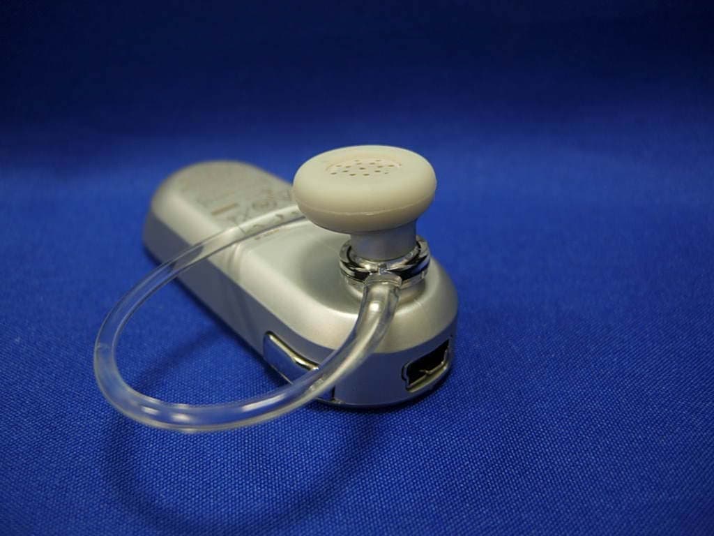
OHH-H385M
Oct 24, 2007BLUETOOTH HEADSET
Equipment Class
DSS - Part 15 Spread Spectrum Transmitter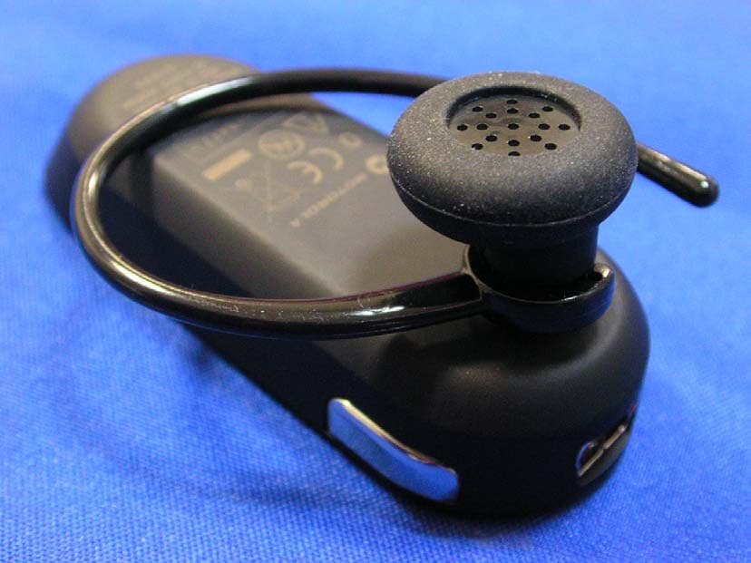
OHH-H385H
Sep 12, 2007Bluetooth Headset
Equipment Class
DSS - Part 15 Spread Spectrum Transmitter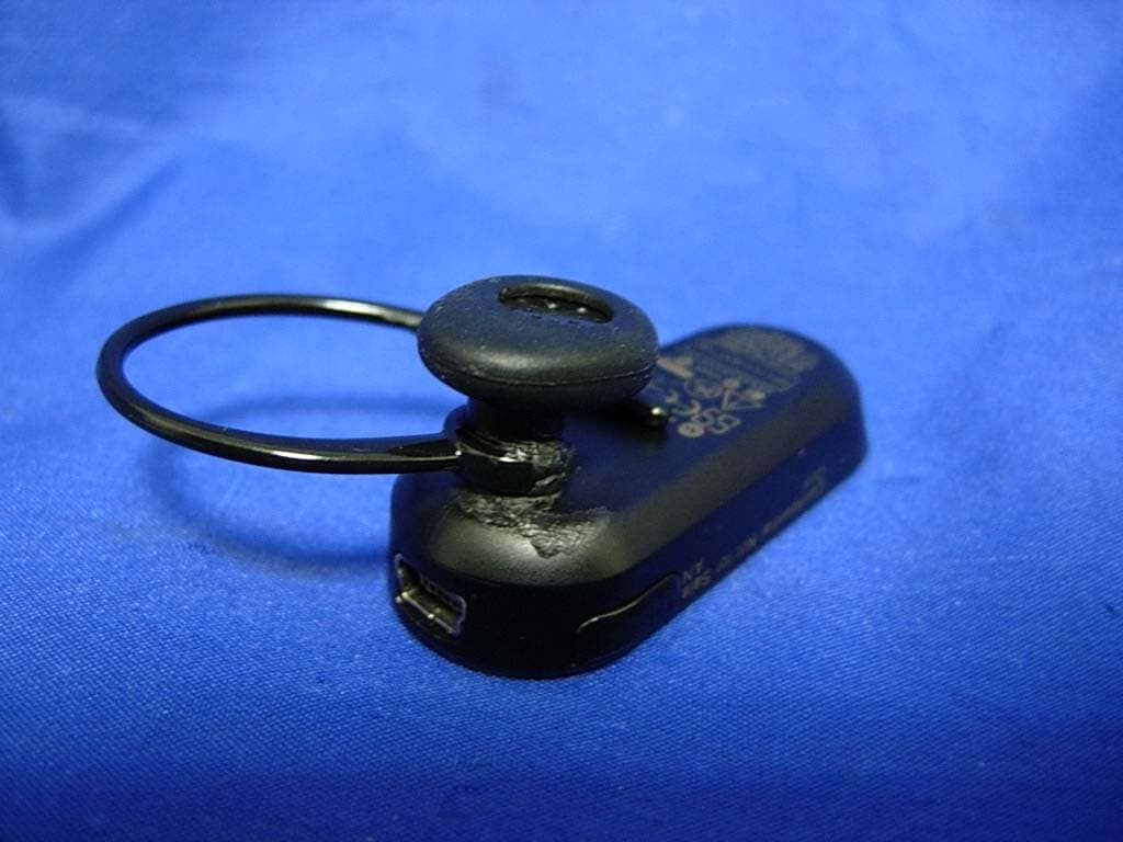
OHH-H375M
Jul 24, 2007BLUETOOTH HEADSET
Equipment Class
DSS - Part 15 Spread Spectrum Transmitter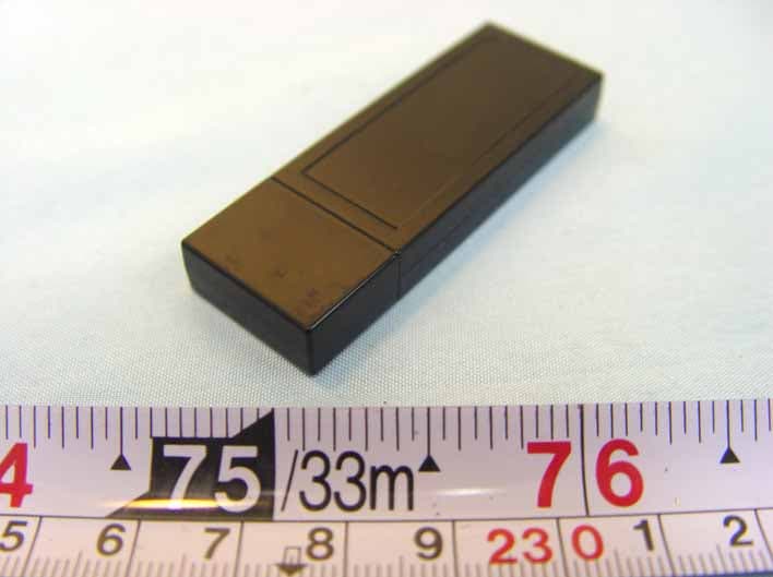
OHH-D200
Feb 07, 2007bluetooth dongle
Equipment Class
DTS - Digital Transmission System