OI4XMTR1MSingle Command Transmitter
Holatron Systems, LLC.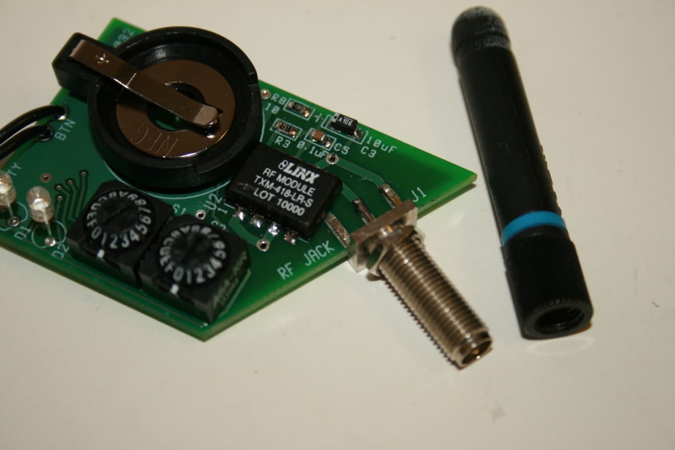
Click to zoom
Application Details
- Equipment Class
- DSC - Part 15 Security/Remote Control Transmitter
- Date of Grant
- Jan 19, 2010
- Application Purpose
- Original Equipment
- Date of Application
- Jan 18, 2010
- Equipment Note
- Single Command Transmitter
- Frequency Range
- 418.00000000 - 418.00000000
- Company
- Holatron Systems, LLC.
- Country
- United States
Documents & Files
Document Text
Text extracted from the exhibit documents filed with the FCC. Open a document above to read the original.
Users Manual
OPERATION & MAINTENANCE GUIDE - XMTR1M Single Command Transmitter HOLATRON SYSTEMS, LLC 833 ILANIWAI ST, STE. 2 Honolulu, HI 96813 (808) 372-0956 www.holatron.com 2 of 8 WARNING Holatron Systems specializes in the design and manufacture of standard and custom electronic control systems where reliability and error free data communication are critical. The transmitter described in this manual is part of a system intended to remotely actuate pyrotechnic or other hazardous devices, and the components of this system have been carefully designed to minimize the possibility of accidental actuation of such devices. Holatron’s design goal is to ensure that data communication errors due to radio interference or to insufficient signal strength due to low battery, exceeding specified range, or conductive objects in the signal path will result in failure of intentional actuation rather than unintended actuation. Techniques used to achieve this design goal are described in section 1.9. Though the probability of unintended actuation is extremely small, it cannot be guaranteed to be zero. Therefore, it is important that the user not enable the receiver until all persons who might be harmed by accidental actuation are in a safe area. As a condition of purchase, the user must acknowledge awareness and agreement that utilization of this product and participation in activities utilizing fireworks, rockets, and explosives is an ultra-hazardous activity carrying implied and explicit risks of injuries and damages to the user and to other participants. The user assumes the risk connected with the utilization of this product and all risks of participation in the activities for which this product is sold. User acknowledges that he/she/it has the necessary and required skill, expertise, training and licensing, as may be applicable or necessary by custom, usage, trade or law, to engage and participate in the ultra-hazardous activities connected with the use, purchase, transportation, or employment of the products sold under this agreement. User acknowledges that Holatron Systems, LLC, has not and will not conduct any investigation into the skill, expertise, training and licensing, as may be applicable or necessary by custom, usage, trade or law, of the user or of user’s agents, employees and assigns, to engage and participate in the ultra-hazardous activities connected with the use, purchase, transportation, or employment of this product. User specifically agrees that Holatron Systems, LLC, its officers, employees, and agents shall not be liable for any claim, demand, cause of action of any kind whatsoever for, or on account of death, personal injury, property damage or loss of any kind resulting from or related to user’s or user’s employees’, agents’ or assigns’ use of this product, and user agrees to indemnify, defend in any action at law, and hold harmless Holatron Systems, LLC, from same, whether brought by the user, user’s agent, or assigns, or any third party. 3 of 8 NOTE: This device complies with part 15 of the FCC Rules contained in CFR 47. It has been assigned FCC ID number: OI4XMTR1M. Operation is subject to the following two conditions: (1) This device may not cause harmful interference, and (2) this device must accept any interference received, including interference that may cause undesired operation. Any changes or modifications to the hardware not expressly approved by the party responsible for compliance could void the user’s authority to operate the equipment. NOTE: This equipment has been tested and found to comply with the limits for a Class B digital device, pursuant to part 15 of the FCC Rules contained in CFR 47. These limits are designed to provide reasonable protection against harmful interference in a residential installation. This equipment generates, uses and can radiate radio frequency energy and, if not installed and used in accordance with the instructions, may cause harmful interference to radio communications. However, there is no guarantee that interference will not occur in a particular installation. If this equipment does cause harmful interference to radio or television reception, which can be determined by turning the equipment off and on, the user is encouraged to try to correct the interference by one or more of the following measures: —Reorient or relocate the receiving antenna. —Increase the separation between the equipment and receiver. —Connect the equipment into an outlet on a circuit different from that to which the receiver is connected. —Consult the dealer or an experienced radio/TV technician for help. 4 of 8 This manual is divided into two sections. The first is a description of the system hardware. The second covers the recommended operating and maintenance procedure. 1.0 HARDWARE DESCRIPTION. The model XMTR1M Single Command Transmitter is a low power hand-held remote control transmitter which transmits a single fixed encoded command with an attached channel number code and group number code while its external pushbutton is pressed. No transmission occurs while its button is not pressed. The transmitted channel number code and group number code are determined by the settings of their respective internal digital switches. Only those receivers which match the transmitted codes will be activated by the transmission. Transmission occurs on 418 MHz with amplitude modulation of the carrier (binary “1” = carrier on, binary “0” = carrier off). The transmitter’s frequency is synthesized via phase-locked loop referenced to a high precision crystal oscillator for exceptional stability and minimum influence by antenna proximity. No alignment or tuning procedures are ever required to maintain optimum performance. There are six different selectable digital channel numbers. Transmitters set to separate digital channel numbers can transmit simultaneously without interfering with each other, even though they operate on the same frequency. This permits up to six different receivers …
Text truncated - open the document above for the full version.
Cover Letter(s)
21 Dec 2009 Nemko Canada Inc 303 River Road Ottawa, Ontario, Canada K1V 1H2 Attn: Director of Certification FCC ID: OI4XMTR1M Authority to Act as Agent On our behalf, I appoint Ferdinand Custodio of Nemko USA Inc., 11696 Sorrento Valley Rd, San Diego, CA, USA to act as our agent in the preparation of this application for equipment certification. I certify that submitted documents properly describe the device or system for which equipment certification is sought. I also certify that each unit manufactured, imported or marketed, as defined in Federal Communication Commission’s regulations will have affixed to it a label identical to that submitted for approval with this application. For instances where our authorized agent signs the application for certification on our behalf, I acknowledge that all responsibility for complying with the terms and conditions for certification, as specified by Nemko Canada Inc, still resides with Holatron Systems LLC, 833 ILANIWAI ST., Ste 2, Honolulu, HI 96813 , expiring 21 June 2009. Sincerely, Charles R. Holdaway, Chief Executive Officer Holatron Systems LLC Holatron Systems LLC 833 Ilaniwai St., Ste. 2, Honolulu, HI 96813 Phone: 808-372-0956 | Fax: 808-732-5419 [email protected] | www.holatron.com SAFE AND RELIABLE WIRELESS ACTUATION SYSTEMS
Cover Letter(s)
21 Dec 2009 Nemko Canada Inc 303 River Rd. Ottawa, Ontario, Canada K1V 1H2 Re: Request of Confidentiality for FCC ID#: OI4XMTR1M Pursuant to Sections 0.457(d)(I)(ii) and 0.459 of the Commission’s Rules, the Applicant hereby requests confidential treatment of information accompanying as outlined below: Schematics, Parts List, Operating Description, Block Diagrams The above materials contain trade secrets and proprietary information not customarily released to the public. The public disclosure of these matters might be harmful to the Applicant and provide unjustified benefits to its competitors. The Applicant understands that pursuant to Rule 0.457(d)(I)(ii), disclosure of this Application and all accompanying documentation will not be made before the date of the Grant for this Application. Sincerely, Charles R. Holdaway, Chief Executive Officer Holatron Systems LLC Holatron Systems LLC 833 Ilaniwai St., Ste. 2, Honolulu, HI 96813 Phone: 808-372-0956 | Fax: 808-732-5419 [email protected] | www.holatron.com SAFE AND RELIABLE WIRELESS ACTUATION SYSTEMS
External Photos
FCC ID: OI4XMTR1M
External Photos
FCC ID: OI4XMTR1M
ID Label/Location Info
Model: XMTR1M S/N:10001 FCC ID: OI4XMTR1M 1.75 " 0.5 " D C B A 4321 D C B A 4321 Holatron Systems LLC 833 ILANIWAI ST., STE. 2 Honolulu, HI 96813 808-372-0956 www.holatron.com SIZEFSCM NODWG NOREV AXMTR1M_FCC_LABEL1 SCALE 1 : 1 SHEET 1 OF 1 DATE 12/21/09 REV.DESCRIPTIONDATEBY DRAWN BY C. HOLDAWAY 12/21/09 DESCRIPTION Artwork - FCC Label for XMTR1M Transmitter NOTES: UNLESS OTHERWISE SPECIFIED 1. Label material - black text on bright metallic, self-adhesive, tamper resistant per HME #371-G089. Location of label Label Artwork (1:1) This device complies with part 15 of the FCC Rules. Operation is subject to the following two conditions: (1) This device may not cause harmful interference, and (2) this device must accept any interference received, including interference that may cause undesired operation.
Internal Photos
FCC ID: OI4XMTR1M
Test Report
Nemko USA, Inc. 11696 Sorrento Valley Rd., Suite F San Diego, CA 92121-1024 Phone (858) 755-5525 Fax (858) 452-1810 FCC Part 15 Subpart C, 15.231: 11/01/2010 CERTIFICATION TEST REPORT Report Number: 2009 12139961 FCC Project Number: 40809-1 Nex Number: 139961 Applicant: H OLATRON SYSTEMS LLC 833 ILANIWAI ST., STE. 2 H ONOLULU, HI 96813 USA Equipment Under Test (EUT): ENCODED REMOTE CONTROL TRANSMITTER Model: XMTR1M FCC ID: OI4XMTR1M In Accordance With: FCC Part 15 Subpart C, 15.231 Tested By: Nemko USA Inc. 11696 Sorrento Valley Road, Suite F San Diego, CA 92121 Authorized By: Alan Laudani, EMC/RF Test Engineer Date: December 9, 2009 Total Number of Pages: 20 Nemko USA, Inc. 11696 Sorrento Valley Road, Suite F, San Diego, CA 92121 Phone (858) 755-5525 Fax (858) 452-1810 FCC ID: OI4XMTR1M Report Number: 2009 12139961 FCC Specification: FCC Part 15 Subpart C, 15.231 Page 2 Section1: Summary of Test Results General All measurements are traceable to national standards These tests were conducted on a sample of the equipment for the purpose of demonstrating compliance with FCC Part 15. Radiated tests were conducted is accordance with ANSI C63.4-2003. Radiated emissions are made on an open area test site. A description of the test facility is on file with the FCC. The assessment summary is as follows: Apparatus Assessed: Encoded Remote Control Transmitter Model: XMTR1M Specification: FCC Part 15 Subpart C, 15.231 Date Received in Laboratory: December 9, 2009 Compliance Status: Complies Exclusions: None Non-compliances: None Nemko USA, Inc. 11696 Sorrento Valley Road, Suite F, San Diego, CA 92121 Phone (858) 755-5525 Fax (858) 452-1810 FCC ID: OI4XMTR1M Report Number: 2009 12139961 FCC Specification: FCC Part 15 Subpart C, 15.231 Page 3 1.1 Report Release History REVISION DATE COMMENTS - December 9, 2009 Prepared By: Ferdinand Custodio - December 9, 2009 Initial Release: Alan Laudani Note that the results contained in this report relate only to the items tested and were obtained in the period between the date of initial receipt of samples and the date of issue of the report. This test report has been completed in accordance with the requirements of ISO/IEC 17025. Nemko USA Inc. authorizes the applicant to reproduce this report provided it is reproduced in its entirety and for use by the company’s employees only. Any use which a third party makes of this report, or any reliance on or decisions to be made based on it, are the responsibility of such third parties. Nemko USA Inc. accepts no responsibility for damages, if any, suffered by any third party as a result of decisions made or actions based on this report. TESTED BY: ___________________________________ Date: December 9, 2009 Ferdinand Custodio, EMC Test Engineer Nemko USA, Inc. 11696 Sorrento Valley Road, Suite F, San Diego, CA 92121 Phone (858) 755-5525 Fax (858) 452-1810 FCC ID: OI4XMTR1M Report Number: 2009 12139961 FCC Specification: FCC Part 15 Subpart C, 15.231 Page 4 TABLE OF CONTENTS Section1: Summary of Test Results ............................................................................ 2 1.1 Report Release History ..................................................................................... 3 Section 2: Equipment Under Test ................................................................................ 5 2.1 Product Identification ........................................................................................ 5 2.2 Samples Submitted for Assessment ................................................................. 5 2.3 Theory of Operation .......................................................................................... 6 2.4 Technical Specifications of the EUT ................................................................. 6 Section 3: Test Conditions ........................................................................................... 7 3.1 Specifications .................................................................................................... 7 3.2 Deviations from Laboratory Test Procedures .................................................... 7 3.3 Test Environment .............................................................................................. 7 3.4 Test Equipment ................................................................................................. 8 Section 4: Observations ............................................................................................... 9 4.1 Modifications Performed During Assessment ................................................... 9 4.2 Record Of Technical Judgements ..................................................................... 9 4.3 EUT Parameters Affecting Compliance ............................................................ 9 4.4 Test Deleted ...................................................................................................... 9 4.5 Additional Observations .................................................................................... 9 Section 5: Results Summary ...................................................................................... 10 5.1 Test Results .................................................................................................... 10 Appendix A: Test Results ........................................................................................... 11 Section 15.231(a)(1) – Transmitter deactivation within 5 seconds ................................ 11 Section 15.231(c) – 20 dB Bandwidth ........................................................................... 13 Section 15.231(b) – Field Strength of Emissions .......................................................... 15 Duty Cycle Calculations ................................................................................................ 18 Appendix B: Block Diagram of Test Setups ............................................................. 20 Nemko USA, Inc. 11696 Sorrento Valley Road, Suite F…
Text truncated - open the document above for the full version.
Test Setup Photos
FCC ID: OI4XMTR1M “X”axis “Y”axis “Z”axis
Contact Information
Applicant
Charles R Holdaway(CEO)
Technical Contact
Holatron Systems, LLCCharles Roy Holdaway
[email protected]808-372-0956
833 Ilaniwai St., Ste. 2 · Honolulu · United States
Non-Technical Contact
Holatron Systems, LLCCharles Roy Holdaway
[email protected]808-372-0956
Test Firm
Nemko USA, Inc. - San Diego EMC DivisionJan Blomgren
[email protected]760-444-3500
Technical Specifications
| # | Rule Parts | Frequency Range | Power Output |
|---|---|---|---|
| 1 | 15.231 | 418 MHz - 418 MHz | - |
Other Applications from Holatron Systems, LLC.
OI4XMTR12C
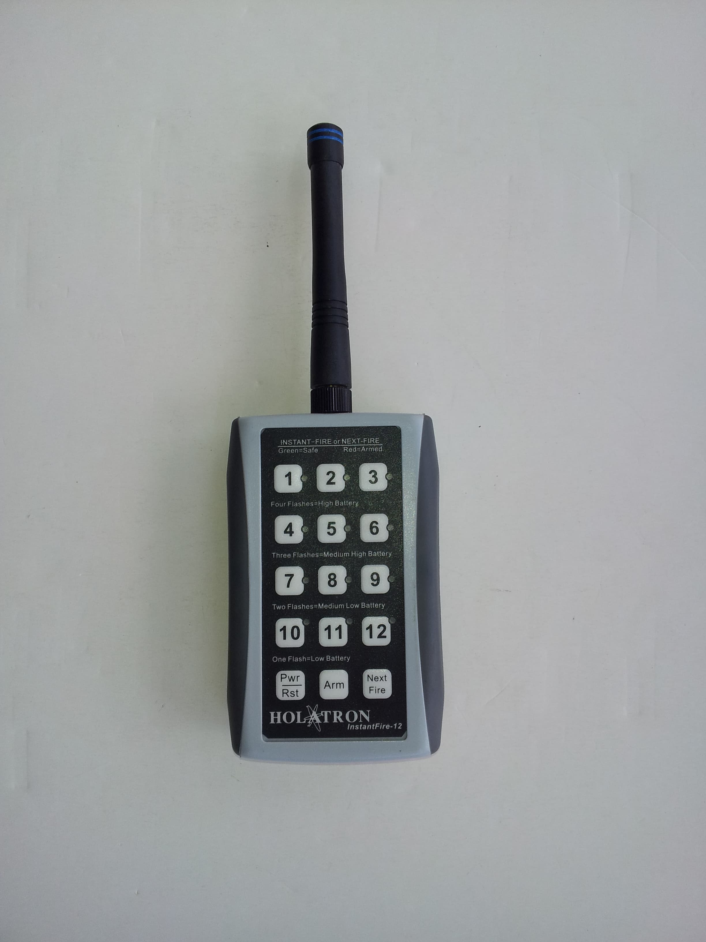
Oct 01, 2015High Speed 12 command transmitter
Equipment Class
DSC - Part 15 Security/Remote Control Transmitter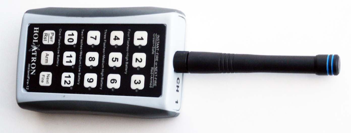
OI4XMTR12B
May 19, 2014Twelve Command Remote Control Transmitter
Equipment Class
DSC - Part 15 Security/Remote Control TransmitterOI4RFLS1XT
Aug 26, 1999DSC - Part 15 Security/Remote Control Transmitter
Equipment Class
DSC - Part 15 Security/Remote Control Transmitter