OIIRM1900-1GSM (PCS1900) Radio Module(data) for fixed and mob
Omnipoint Technologies, Incorporated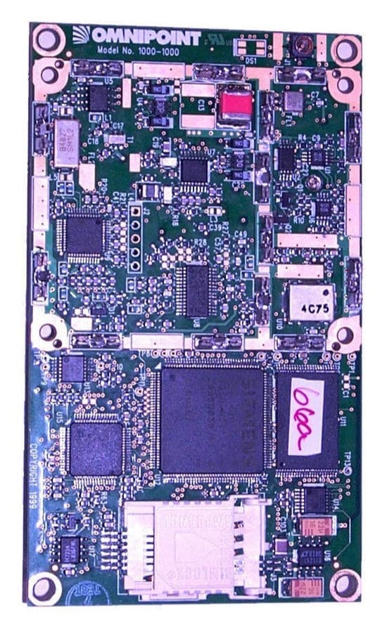
Click to zoom
Application Details
- Equipment Class
- PCB - PCS Licensed Transmitter
- Date of Grant
- Jan 05, 2000
- Application Purpose
- Original Equipment
- Date of Application
- Aug 05, 1999
- Equipment Note
- GSM (PCS1900) Radio Module(data) for fixed and mob
- Frequency Range
- 1850.20000000 - 1909.80000000
- Country
- United States
Documents & Files
Document Text
Text extracted from the exhibit documents filed with the FCC. Open a document above to read the original.
Users Manual
Eagle Technical Specification v.0067/30/99 This document is in DRAFT format and is subject to change at Omnipoint Technologies sole discretion at any time. .......... . . . . . . . Wireless Solutions Division Omnipoint Technologies, Inc. Eagle TM Technical Specification GSM Wireless Modules Wireless Solutions Division Omnipoint Technologies, Inc. 1365 Garden of the Gods Road Colorado Springs, CO 80907 www.omnipoint-tech.com Eagle Technical Specification v.0067/30/99 This document is in DRAFT format and is subject to change at Omnipoint Technologies sole discretion at any time. 2 Important Safety Information Some of the following information may not apply to all devices described in this manual. However, precautions should be observed when handling any electrical device. ♦ Save this manual, it contains important safety information and operating instructions. ♦ Do not expose this product to open flames. ♦ Care should be taken so that liquids do not spill into the device. ♦ Do not attempt to disassemble the product. Doing so will void warranty. This product does not contain consumer serviceable components. (This does not apply to Subscriber Identification Modules (SIMs)). Guidelines for Safe Use The Eagle TM products are a radio transmitter and receiver intended for fixed and mobile uses only. They comply with the RF hazard requirements applicable to fixed PCS equipment operating under the authority of 47 CFR Part 24, Subpart E of the FCC Rules and Regulations when installed properly. The Eagle TM products comply with FCC requirements for Human Exposure by meeting these requirements: 1. The device’s antenna must be installed no closer than 20 cm to any person. 2. Only fixed and mobile applications are permitted. 3. Portable applications (within 20 cm of any person) are strictly prohibited. 4. Antenna gain is limited to a maximum of 7 dBi for fixed applications. 5. Antenna gain is limited to a maximum of 3 dBi for mobile applications. Eagle Technical Specification v.0067/30/99 This document is in DRAFT format and is subject to change at Omnipoint Technologies sole discretion at any time. 3 Eagle TM Technical Specification GSM Wireless Modem INTRODUCTION ........................................................................................................................................... 4 GSM Overview ................................................................................................................................ 5 EAGLE TM ONE PRODUCT DESCRIPTION (SUMMARY) ........................................................................ 6 TECHNICAL SPECIFICATIONS (DETAILED) ........................................................................................... 8 Physical ............................................................................................................................................ 8 Environmental .................................................................................................................................. 9 Interfaces ......................................................................................................................................... 9 Status Indication............................................................................................................................. 12 Modes of Operation................................................................................................................................... 13 Circuit Switched Data ..................................................................................................................... 13 SMS ............................................................................................................................................... 13 USSD ............................................................................................................................................. 14 VOICE ............................................................................................................................................ 14 SOFTWARE INTERFACE.......................................................................................................................... 15 AT Command Set .......................................................................................................................... 15 Eagle TM Module Initialization and Setup Examples ........................................................................ 18 INTEGRATION AND TEST CONSIDERATIONS..................................................................................... 22 GLOSSARY/ACRONYMS.......................................................................................................................... 23 APPENDIX A: REGULATORY INFORMATION ..................................................................................... 25 Eagle Technical Specification v.0067/30/99 This document is in DRAFT format and is subject to change at Omnipoint Technologies sole discretion at any time. 4 INTRODUCTION The Eagle TM family of products is centered around the fully type approved Eagle TM Data Module, a compact, wireless OEM module that utilizes the international standard Global System for Mobility (GSM) enabling low-cost, application-specific, two-way communication and control. It takes full advantage of GSM capabilities such as Subscriber Identity Modules (SIMs), which are “smart cards” that provide numerous advantages. Over-the-air communication lets the Eagle TM 2000 terminal accomplish tasks that previously required on- site visits and offers innovative new services. In addition, terminal authentication and data encryption ensure confidential communication between the terminal user and the data recipient. The Eagle TM modules are available in several variations. 1900MHz modules are available for integration and deployment in North America and elsewhere the 1900 MHz PCS band is allocated. 900 and 1800 MHz modules are also available for rest of wo…
Text truncated - open the document above for the full version.
Users Manual
Redhawk Installation Manual, v.00A8/5/99 This document is in DRAFT format and is subject to change at Omnipoint Technologies sole discretion at any time. .......... Wireless Solutions Division Omnipoint Technologies, Inc. Redhawk TM Users Guide GSM Wireless Terminal Wireless Solutions Division Omnipoint Technologies, Inc. 1365 Garden of the Gods Road Colorado Springs, CO 80907 www.omnipoint-tech.com 2 This document is in DRAFT format and is subject to change at Omnipoint Technologies sole discretion at any time. Section 5 – Compliance Information 1 INSTRUCTIONS TO THE OEM This section summarizes the regulatory responsibilities and actions required of manufacturers and integrators who incorporate OEM versions of the Redhawk™ family of PCS-1900 GSM transceivers (i.e., the Eagle, FCC ID: OIIRM1900-1) into their products. For all such products and in all applications, appropriate instructions, documentation and labels are required to ensure compliance with current FCC guidelines for limiting human exposure to radiofrequency radiation; additionally, in certain situations and applications these products will require additional FCC approvals prior to their sale or operation. For further details on the information presented in this section, please contact Omnipoint Technologies, Inc. 1.1 Introduction The Federal Communications Commission (FCC) is the agency of the Federal Government which oversees all non-governmental radiofrequency transmitters within the United States. Products incorporating the Eagle PCS-1900 GSM transceiver operate as Personal Communications Services (PCS) devices under the authority of Part 24, Subpart E— Broadband PCS, of the FCC Rules and Regulations. All such transmitters must be authorized by the FCC through its Certification process, as detailed in Part 2, Subpart J—Equipment Authorization Procedures. Through the Certification process, the FCC verifies that the product complies with all applicable regulatory and technical requirements, including those which address human exposure to radiofrequency radiation. In general, radiofrequency transmitters cannot be sold or operated in the US prior to FCC approval. To comply with the requirements of the National Environmental Policy Act (NEPA) of 1969, operation of an FCC-regulated transmitter may not result in human exposure to radiofrequency radiation in excess of the applicable health and safety guidelines established by the FCC. Further information on RF exposure issues may be found in the FCC's Office of Engineering and Technology (OET) Bulletin Number 65, "Evaluating Compliance with FCC Guidelines for Human Exposure to Radiofrequency Electromagnetic Fields" and Supplement C, "Additional Information for Evaluating Compliance of Mobile and Portable Devices with FCC Limits for Human Exposure to Radiofrequency Emissions." Both of these documents are available via the internet at the OET website (http://www.fcc.gov/oet). The Eagle has been approved by the FCC for use in OEM products contingent upon the following conditions which form an integral part of the grant of equipment authorization: This modular transmitter is for OEM integration into final products with antenna gain not exceeding 3 dBi, installed and operated with a separation distance of 20 cm or more between the antenna and all persons for satisfying RF exposure requirements of 2.1091. Final products must provide operating instructions to the end users for satisfying RF exposure compliance. A warning label visible to all persons exposed to the antenna and identical to that described in the filing must be displayed on or next to the antenna. The total system output must not exceed 2.0 W EIRP. Separate approval for RF exposure compliance is required for this module to operate in products that do not satisfy the conditions of this grant. Depending upon the application and type of product into which the Eagle is to be incorporated, specific OEM actions and responsibilities required to meet these conditions vary, as is detailed in Section 28.3. However, in all cases the primary concern is to ensure 3 This document is in DRAFT format and is subject to change at Omnipoint Technologies sole discretion at any time. compliance with current FCC guidelines and regulations which limit human exposure to radiofrequency radiation. 1.2 Definitions For the purpose of determining compliance with current FCC regulations addressing human exposure to radiofrequency radiation, the FCC has established the following three categories of transmitting devices: • Portable Devices – devices where the antenna is located within 20 cm (7.78 inches) of any person, including the user, if applicable. Portable devices operating under the authority of Part 24 (Broadband PCS) are limited to a maximum of 2 W equivalent isotropically radiated power (EIRP). • Mobile Devices – devices designed to be used in other than fixed locations and generally such that the antenna is located a minimum of 20 cm (7.78 inches) from any person, including the user, if applicable. Mobile devices operating under the authority of Part 24 (broadband PCS) are limited to a maximum of 2 W equivalent isotropically radiated power (EIRP). • Fixed devices – devices in which the antenna, either integral to the product or remotely located, is physically secured at one location and is not able to be easily moved to another location. 1.3 OEM Responsibilities for All Products Containing the RM1900-1 In addition to any other regulatory requirements, OEMs and integrators must include or provide the following information, instructions, warnings and labels with any device or product into which the Eagle PCS-1900 GSM transceiver has been incorporated: 1. Detailed Operating Instructions for Ensuring Compliance with Current FCC Guidelines Which Limit Human Exposure to Radiofrequency Radiation The OEM must provide an operating/installation manual with the final product which clearly indicates that the following operating conditions and restrictions…
Text truncated - open the document above for the full version.
Attestation Statements
Omnipoint Technologies, Inc.Attestation FCC ID: OIIRM1900-1Page 1 of 1 This document contains PROPRIETARY and CONFIDENTIAL information of Omnipoint Technologies, Inc. ATTESTATION OF COMPLIANCE TESTING The Omnipoint Radio Module (FCC ID: OIIRM1900-1) has been tested in accordance with the requirements of the Federal Communications Commission to obtain a CERTIFICATION grant of equipment authorization as described in Parts 2 and 24 of the FCC Rules and Regulations, namely 47 CFR Part 2, Subpart J, which details equipment authorization procedures, and 47 CFR Part 24, Subpart E, which sets out the regulations governing broadband personal communications services (PCS) operating in the 1850-1910 and 1930-1990 MHz bands. All tests were performed using measurement procedures and practices consistent with the aforementioned regulations and with industry standards. Each unit manufactured and marketed will conform to the sample tested and the data reported in this filing is representative of the equipment being produced, within the variations that can be expected due to quantity production and testing on a statistical basis. To the best of our knowledge, we certify that the facts set forth in this document and the accompanying technical data are true and correct. We further certify that the measurements described in this document were performed under our direction and supervision at the following locations: Omnipoint Technologies, Inc. 1365 Garden of the Gods Road Colorado Springs, CO 80907 Criterion Technology 1350 Country Road 16 Rollinsville, CO 80474 NAME:Kelly RogersJames Youngman COMPANY:Omnipoint Technologies, Inc.Omnipoint Technologies, Inc. TITLE:Product Design EngineerRegulatory Compliance Consultant SIGNED:____________________________________________________ DATE:August 06, 1999_________ ____August 06, 1999 ______________
Cover Letter(s)
August 06, 1999 Federal Communications Commission Equipment Authorization Division Application Processing Branch 7435 Oakland Mills Road Columbia, MD 21046 ATTN:Mr. Greg Czumak RE:Certification Application for FCC ID: OIIRM1900-1 Dear Greg, In fulfillment of the requirements to obtain a CERTIFICATION grant of equipment authorization for equipment operating under 47 CFR Part 24, Subpart E—Broadband PCS, Omnipoint Technologies, Inc. (OTI) respectfully submits for your consideration the attached filing for FCC ID: OIIRM1900-1. Included in this electronic submittal are Form 731, Application for Equipment Authorization; Form 159, Remittance Advice and payment in the amount of $610.00; and the documentation and technical information required by 47 CFR Part 2, Subpart J—Equipment Authorization Procedures, Section 2.1033 Application for Certification. Pursuant to Section 0.459 of the Commission's Rules, Omnipoint Technologies, Inc. respectfully requests confidentiality for the following exhibits, and that they be withheld from public inspection at the conclusion of the authorization process: Exhibit 4Tune-Up Procedure Exhibit 5Schematic Diagrams These exhibits contain material considered to be trade secrets of OTI and, as considerable effort has been expended in the development of this product, it is imperative that our competitors do not receive an unfair advantage in the marketplace at the expense of OTI. Should you require any further or additional information to process this application, please do not hesitate to contact me directly. I can be reached by any of the following means: Telephone:(719) 548-1201 X1218 Fax::(719) 266-8521 email:[email protected] Sincerely, Steve Parker Project Manager, Core Development Wireless Solutions Division
ID Label/Location Info
Omnipoint Technologies, Inc.Exhibit 7 FCC ID: OIIRM1900-1Page 1 of 1 This document contains PROPRIETARY and CONFIDENTIAL information of Omnipoint Technologies, Inc. EXHIBIT 7 FCC LABELING INFORMATION As required by § 2.1033(c)(11), this exhibit details the FCC Identifier label and its placement on the RM. A drawing representative of the actual FCC Identifier label is shown in Figure E7.1; the label itself will be permanently affixed to the RM itself as shown in the photo presented as Figure E7.2. Figure E7.1 FCC Label. Figure E7.2. Photograph of RM showing FCC Identifier label placement.
Internal Photos
Omnipoint Technologies, Inc.Exhibit 8 FCC ID: OIIRM1900-1Page 1 of 5 This document contains PROPRIETARY and CONFIDENTIAL information of Omnipoint Technologies, Inc. EXHIBIT 8 EQUIPMENT PHOTOGRAPHS This exhibit contains a series of digital photographs, as required by § 2.1033(c)(12) which reveal equipment construction and layout, including internal views showing component placement and chassis assembly. Table E18.1. Equipment photographs—photo numbers and description. Photo Number Description 1Top of RM PCB 2Bottom of RM PCB 3Top of RM PCB with RF shields covering radio circuitry 4Bottom of RM PCB with RF shields covering radio circuitry Omnipoint Technologies, Inc.Exhibit 8 FCC ID: OIIRM1900-1Page 2 of 5 This document contains PROPRIETARY and CONFIDENTIAL information of Omnipoint Technologies, Inc. Photo 1. Top of RM PCB. Omnipoint Technologies, Inc.Exhibit 8 FCC ID: OIIRM1900-1Page 3 of 5 This document contains PROPRIETARY and CONFIDENTIAL information of Omnipoint Technologies, Inc. Photo 2. Bottom of RM PCB. Omnipoint Technologies, Inc.Exhibit 8 FCC ID: OIIRM1900-1Page 4 of 5 This document contains PROPRIETARY and CONFIDENTIAL information of Omnipoint Technologies, Inc. Photo 3. Top of RM PCB with RF shields covering radio circuitry. Omnipoint Technologies, Inc.Exhibit 8 FCC ID: OIIRM1900-1Page 5 of 5 This document contains PROPRIETARY and CONFIDENTIAL information of Omnipoint Technologies, Inc. Photo 4. Bottom of RM PCB with RF shields covering radio circuitry.
Operational Description
Omnipoint Technologies, Inc. FCC ID: OIIRM1900-1Page 1 of 1 This document contains PROPRIETARY and CONFIDENTIAL information of Omnipoint Technologies, Inc. LIST OF EXHIBITS EXHIBIT47 CFR §§CONTENTS 1:2.1033(a) & (c)General Information for Certification 2:2.1033(c)(3)/24.52Installation and Instruction Manual including Human Exposure Compliance Statement 3:2.1033(c)(8)DC Voltages Applied to and Currents into Final Amplifying Device *4:2.1033(c)(9)Tune-up Procedure *5:2.1033(c)(10)Schematic Diagrams 6:2.1033(c)(10)Means for Determining and Stabilizing Frequency, Suppression of Spurious Radiation, Limiting Modulation, and Limiting Power 7:2.1033(c)(11)FCC Labeling Information 8:2.1033(c)(12)Equipment Photographs 9:2.1033(c)(13)Detailed Description of Modulation System 10:2.1033(c)(14)General Measurement Information 11:2.1046/24.232(a)RF Output Power Measurements 12:2.1049Occupied Bandwidth Measurements 13:2.1051/24.238(a)Conducted Spurious Emissions Measurements 14:2.1053Radiated Spurious Emissions Measurements 15:2.1055/24.235Frequency Stability Measurements * = Exhibit filed confidentially with the FCC Omnipoint Technologies, Inc.Exhibit 1 FCC ID: OIIRM1900-1Page 1 of 6 This document contains PROPRIETARY and CONFIDENTIAL information of Omnipoint Technologies, Inc. EXHIBIT 1 GENERAL INFORMATION FOR CERTIFICATION The information provided in this exhibit is submitted in response to the requirements of § 2.1033 Application for a certification grant of equipment authorization. General Description of Equipment (Informative) The Omnipoint Technologies, Inc. (OTI) Eagle One 1900MHz Radio Module, Model Number 1000-1000, FCC ID: OIIRM1900-1, is a Radio Module which operates under the authority of Part 24, Subpart E—Broadband PCS. The Radio Module allows a customer designed application to access the Global System for Mobility, or GSM, network, and ultimately the Public Switched Telephone Network (PSTN) or the internet. As a GSM radio module, the RM complies with applicable national (PCS-1900) and international (GSM-900) standards including, for example, J-STD-007, PCS Air Interface Specification, and the family of international standards for GSM equipment. Initially intended for fixed uses, the RM may be used to wirelessly transmit and receive data, enabling a variety of applications from Automated Meter Reading (AMR) to wireless alarms, e-mail and internet access. These types of PCS applications were made possible by the FCC's adoption in June 1996 of rules permitting flexible service offerings in the commercial mobile radio services (WT Docket No. 96-6, FCC 96-83, "Amendment of the Commission's Rules to Permit Flexible Service Offerings in the Commercial Mobile Radio Services, First Report and Order and Further Notice of Proposed Rulemaking," released August 1, 1996, ¶ 29). The Commission's ruling in this proceeding concluded that fixed services, such as those made possible by the RM, are permissible service offerings on spectrum allocated for broadband PCS. An overview of RM deployment in a GSM network is shown in Figure E1.1. Functional capabilities of the RM include circuit switched data up to 9.6 kpbs, as well as other GSM services for transmitting and receiving data (Short Message Service—SMS, and Unstructured Supplementary Service Data—USSD). The RM has been designed to operate over an industrial temperature range (-20°C to +60° C) and a fixed DC input voltage of +5 VDC. Communication between the host application and the RM is via a sixty pin molded connector using TTL voltage levels. Physically, the RM consists of a single printed circuit board (PCB) of approximate dimensions 4.25" x 2.5". Major components include a system controller, GSM radio, and a Subscriber Identity Module (SIM). The equipment described in this application is functionally equivalent to the GSM radio portion of the DTSA module previously authorized under FCC ID: OIIDTSA1900-2, encompassing model number 2000-1001. Omnipoint Technologies, Inc.Exhibit 1 FCC ID: OIIRM1900-1Page 2 of 6 This document contains PROPRIETARY and CONFIDENTIAL information of Omnipoint Technologies, Inc. User Application Server INTERNET Eagle TM Module Base Transceiver Station (BTS) GSM V.24 Serial I/F Mobile Switching Center (MSC) Short Message Service Center (SMSC) SS7, T1, etc. Base Station Controller (BSC) PSTN SMS DATA PATH CIRCUIT SWITCHED DATA PATH User MODEM Interworking Function (IWF) Custom Packaging Custom Application Figure E1.1. RM Deployment in a GSM Network. The "Eagle One" product line is a family of wireless (GSM) radio products, of which the RM is the first offering, as well as the core module on which all other products are based. As described in the technical specification, the "Eagle One" product line currently consists of the following models: • 1000-1000 RMOEM version of a GSM radio implemented on a single PCB and the subject of this filing (FCC ID: OIIRM1900-1). Functionally equivalent to the radio portion of the Redhawk Model 2000-1001 (FCC ID: OIIDTSA1900-2), the subject of a previous authorization application. Using an MMCX type connector for the RF output. • 1010-1000 RMOEM version of a GSM radio implemented on a single PCB. Identical to model number 1000-1000 using an SMA type connector for the RF output. Omnipoint Technologies, Inc.Exhibit 1 FCC ID: OIIRM1900-1Page 3 of 6 This document contains PROPRIETARY and CONFIDENTIAL information of Omnipoint Technologies, Inc. Section 2.1033(a)Application for certification A completed FCC Form 731 “Application for Equipment Authorization” accompanies this document, both of which have been filed electronically. Section 2.1033(c)(1)Name of Applicant Applicant:Omnipoint Technologies, Inc. 1365 Garden of the Gods Road Colorado Springs, CO 80907 Manufacturer:Siemens Energy & Automation, INC. 3000 Bill Garland Road Johnson City, TN 37601 Siemens is a contract manufacturer and will be the final manufacturer of the equipment described in this application for Omnipoint Technologies, Inc. Se…
Text truncated - open the document above for the full version.
Operational Description
Omnipoint Technologies, Inc.Exhibit 3 FCC ID: OIIRM1900-1Page 1 of 1 This document contains PROPRIETARY and CONFIDENTIAL information of Omnipoint Technologies, Inc. EXHIBIT 3 DC VOLTAGES AND CURRENTS INTO FINAL RADIO AMPLIFYING DEVICE As required by § 2.1033(c)(8), presented in Table E3.1 are the DC voltages applied to and the corresponding DC currents into the final RF power amplifier, over the entire range of nominal RF output powers that the RM normally operates. Table E3.1 Final power amplifier—DC voltages and currents NominalFinal PA Output Power (dBm) Input Voltage (Volts) Input Current (mAmps) 302.8971230 282.2381040 261.740850 241.382755 221.131710 200.946697 180.800690 160.681678 140.590667 120.522649 100.457636 80.403624 60.362586 40.325548 20.301530 00.272492
Operational Description
Omnipoint Technologies, Inc.Exhibit 6 FCC ID: OIIRM1900-1Page 1 of 3 This document contains PROPRIETARY and CONFIDENTIAL information of Omnipoint Technologies, Inc. EXHIBIT 6 MEANS FOR DETERMINING AND STABILIZING FREQUENCY, SUPPRESSION OF SPURIOUS RADIATION, LIMITING MODULATION, AND LIMITING POWER As required by § 2.1033(c)(10), this Exhibit details the methods employed within the RM transmitter to determine and stabilize frequency, suppress spurious radiation and to limit both modulation and power Means for Determining and Stabilizing Frequency No absolute frequency stability requirements are levied against broadband PCS equipment operating under the authority of Part 24, Subpart J. However, per § 24.235, the frequency stability of the RM shall be sufficient to ensure that the fundamental emission stays within the authorized frequency block. Specifically, this is accomplished as follows: The transmit RF carrier of the RM is generated by a voltage controlled oscillator (VCO) which is phase locked to a 13 MHz master reference source. This 13 MHz source is synchronized to the GSM network and, within the RM, is controlled by an 11 bit DAC to keep the carrier to within ±0.1 ppm of the network reference. Measurements of the stability of the fundamental emission of the RM, over variations in temperature and input voltage, are presented in Exhibit 14. As a GSM-compliant terminal, the stability of the RM carrier is to within 0.1 ppm of the received frequency from a base station, in accordance with GSM performance requirements (see J-STD-007, Personal Communications Services, Air Interface Specification; Volume 1, Radio Path Physical Layer, Section 7.4.1). Means for Suppression of Spurious Radiation Suppression of spurious and harmonic radiation in the RM is ensured through proper transmitter design, lay-out, and construction. 1. Transmitter Architecture and Design • Frequency plan of the transmitter—local oscillator frequencies were selected to minimize spurious products. • Use of an upconversion loop architecture to minimize spurious and noise power level in the PCS1900 receive band (1930-1990 MHz). • Additional filtering in the T/R switch to further reduce harmonics. Omnipoint Technologies, Inc.Exhibit 6 FCC ID: OIIRM1900-1Page 2 of 3 This document contains PROPRIETARY and CONFIDENTIAL information of Omnipoint Technologies, Inc. 2. Physical Realization of the Transmitter Module • Fully shielded GSM radio module construction with filtering on all signal (data, control, clock) and power supply leads. • Localized shielding over the GSM radio sections. • Careful component placement and layout, multi-layer circuit board construction, microstrip signal routing, and construction techniques to eliminate cavity moding and resonances. Means for Limiting Modulation Per GSM specifications, the modulation scheme implemented by the RM is Gaussian MSK (GMSK), with a bandwidth-time product of BT=0.3. Modulation rate is 1625/6 kbps, or approximately 280.83 kbps. To minimize spreading of the spectrum, GSM standards require that the RF output spectrum meet the mask shown in Figure E6.1. In the RM, modulation accuracy is maintained through the use of direct digital synthesis techniques. -70 -60 -50 -40 -30 -20 -10 0 10 0500100015002000 Frequency Offset from Carrier (kHz) Power Relative to Carrier in 30 kHz BW (dB) Figure E6.1. GSM terminal modulation mask. Omnipoint Technologies, Inc.Exhibit 6 FCC ID: OIIRM1900-1Page 3 of 3 This document contains PROPRIETARY and CONFIDENTIAL information of Omnipoint Technologies, Inc. Means for Limiting Power As a GSM-compliant terminal, the RM will transmit at any of the 16 defined nominal RF output power levels, from 30 dBm to 0 dBm, during its assigned TDMA frame. Transmitter operation (power level and frame) is controlled by the GSM network, specifically by the base station to which the unit is in communication. Maximum RF output power of the RM is set at the factory and cannot be altered or increased. Furthermore, the temporal variation in power level within each transmission (i.e., transmission burst time mask) is in accordance with GSM requirements. This is accomplished by adjusting transmitter gain through a discrete time power control loop and ramping the transmitter on and off at the beginning and ending of each burst. The power control loop is implemented using an open loop technique proven to have little effect on output power versus temperature. Maximum RF power is adjusted to within the specified tolerance during each burst, at the output power level specified by the base station.
Operational Description
Omnipoint Technologies, Inc.Exhibit 9 FCC ID: OIIRM1900-1Page 1 of 2 This document contains PROPRIETARY and CONFIDENTIAL information of Omnipoint Technologies, Inc. EXHIBIT 9 DETAILED DESCRIPTION OF MODULATION SYSTEM A detailed description of the modulation system employed is provided in this exhibit, per the requirements of § 2.1033(c)(13). The following description is taken directly from Chapter 4 of Volume 1, Radio Path Physical Layer, in the Personal Communications Services, Air Interface Specification, J-STD-007. 4.0Modulation This chapter defines the theoretical requirements of the modulator, inclusive of the differential encoder. The modulator receives the bits from the encryption unit and produces and RF modulated signal. The information bits are first differentially encoded and then passed to the modulator. The modulation is GMSK (Gaussian Minimum Shift Keying) with a BT product of 0.3. 4.1Modulation Format 4…
Text truncated - open the document above for the full version.
Contact Information
Applicant
Steven J Parker(Project Manager, Core Development)
Test Firm
Criterion Technology Corp.Lou Schornack
Technical Specifications
| # | Rule Parts | Frequency Range | Power Output | Emission | Tolerance |
|---|---|---|---|---|---|
| 1 | 24 | 1.85 GHz - 1.91 GHz | 1 W | 250KGXW | 3.0000000000 ppm |
Other Applications from Omnipoint Technologies, Incorporated

OIIDTSA1900-2
Aug 30, 1999PCB - PCS Licensed Transmitter
Equipment Class
PCB - PCS Licensed Transmitter