OITAA1000ACOM 1000 HF Liner Ampifier
ACOM International, Inc.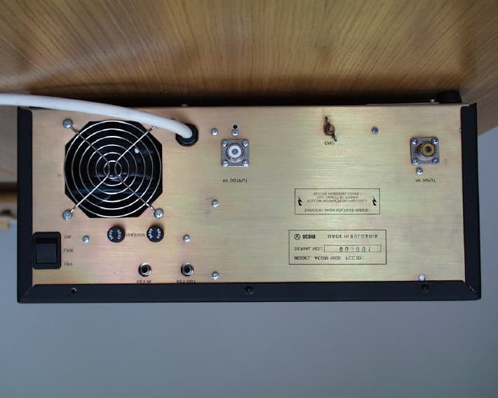
Click to zoom
Application Details
- Equipment Class
- AMP - Amplifier
- Date of Grant
- Dec 12, 2000
- Application Purpose
- Original Equipment
- Date of Application
- Sep 11, 2000
- Equipment Note
- ACOM 1000 HF Liner Ampifier
- Frequency Range
- 50.00000000 - 54.00000000
- Company
- ACOM International, Inc.
- Country
- United States
Documents & Files
Document Text
Text extracted from the exhibit documents filed with the FCC. Open a document above to read the original.
Users Manual
Exhibit 8 1 -17 1 International, Inc. Exhibit 8: User’s Manual External Radio Frequency Power Amplifier ACOM 1000 Model 1000 157 Horse Pond Road, Sudbury, MA 01776 Tel: (978) 440-7555 Fax: (978) 440-9080 e-mail: [email protected] Exhibit 8 2 -17 2 TABLE OF CONTENTS 1. GENERAL INFORMATION..............................................................................................................................2 1-1. INTRODUCTION AND DESCRIPTION.....................................................................................................................2 1-2. OWNER ASSISTANCE.........................................................................................................................................2 1-3. EQUIPMENT SUPPLIED.......................................................................................................................................3 1-4. FEATURES.........................................................................................................................................................3 1-5. SAFETY CONSIDERATIONS, EXPLICIT DEFINITIONS.............................................................................................3 2. INSTALLATION................................................................................................................................................4 2-1. UNPACKING AND INITIAL INSPECTION................................................................................................................4 2-2. LINE VOLTAGE SELECTION................................................................................................................................4 2-3. AMPLIFIER LOCATION SELECTION.....................................................................................................................4 2-4. CONNECTIONS..................................................................................................................................................5 2-5. INSTALLATION OF EXTERNAL FAN.....................................................................................................................6 3. POWER ON, CONTROLS AND INDICATORS.................................................................................................6 4. OPERATION......................................................................................................................................................8 4-1. TURNING ON AND OFF.....................................................................................................................................8 4-2. CHANGING OPERATE AND STANDBY MODES......................................................................................................9 4-3. TUNING............................................................................................................................................................9 4-4 ON LINE INFORMATION SCREENS AND CONTROL FUNCTIONS..........................................................................11 4-5 AUTO-PROTECTION SYSTEM.............................................................................................................................11 5. OFF LINE OPERATION..................................................................................................................................11 5-1 CONTRAST AND BACKLIGHTING CONTROL........................................................................................................12 5-2 AUTO-OPERATE ENABLING AND DISABLING......................................................................................................12 5-3. READING AUTO-PROTECTION SIGNATURES......................................................................................................12 6. MAINTENANCE..............................................................................................................................................12 6-1. CLEANING......................................................................................................................................................12 6-2. FUSES REPLACEMENT.....................................................................................................................................12 6-3. TUBE REPLACEMENT.......................................................................................................................................13 6-4. THE ACOM1000 SIMPLIFIED SCHEMATIC DIAGRAM........................................................................................14 6-5. TROUBLESHOOTING........................................................................................................................................15 7. SPECIFICATIONS...........................................................................................................................................15 7-1. PARAMETERS..................................................................................................................................................15 7-2. FUNCTIONS.....................................................................................................................................................16 7-3. STORAGE AND SHIPMENT................................................................................................................................16 1. GENERAL INFORMATION 1-1. Introduction and Description This manual explains the installation, operation, and maintenance of the ACOM1000 HF+6 meters linear amplifier. The ACOM1000 is a complete and self-contained linear amplifier that covers all amateurs bands from 1.8 through 54MHz and provides over 1000W-output power with less than 60W-exciter drive. Antenna VSWR up to 3:1 is acceptable at full power. Tuning is substantially simplified by a plate-load True Resistance Indicator (TRI) and by an automatically controlled input attenuator. Operating parameters are displayed by a multi-functional backlighted Liquid Crystal Display. Full bre…
Text truncated - open the document above for the full version.
Block Diagram
Exhibit 3Page 1 of 3 1 International, Inc. Exhibit 3: Block Diagram External Radio Frequency Power Amplifier ACOM 1000 Model 1000 157 Horse Pond Road, Sudbury, MA 01776 Tel: (978) 440-7555 Fax: (978) 440-9080 e-mail: [email protected] Exhibit 3Page 2 of 3 2 Exhibit 3Page 3 of 3 3
External Photos
Exhibit 2Page 1 of 3 International, Inc. Exhibit 2: External Photos External Radio Frequency Power Amplifier ACOM 1000 Model 1000 157 Horse Pond Road, Sudbury, MA 01776 Tel: (978) 440-7555 Fax: (978) 440-9080 e-mail: [email protected] Exhibit 2Page 2 of 3 Exhibit 2Page 3 of 3
ID Label/Location Info
Exhibit 1Page 1 of 4 International, Inc. Exhibit 1: ID Label Location Info External Radio Frequency Power Amplifier ACOM 1000 Model 1000 157 Horse Pond Road, Sudbury, MA 01776 Tel: (978) 440-7555 Fax: (978) 440-9080 e-mail: [email protected] Exhibit 1Page 2 of 4 FCC ID and Label Location Information In compliance with FCC Regulation 47 CFR Ch. 1 part 2.925, the ACOM 1000, External Radio Frequency Power Amplifier, Model 1000 bears a label located on the rear plate of the equipment which displays the following FCC Identifier: Part (a) 1. The term FCC ID followed by the three digit Grantee Code and the six digit Equipment Product Code. 2. Not applicable. 3. Not applicable. Part (b) Not applicable Part (c) Reserved Part (d) 1. The ACOM 1000 label is indelibly printed on the rear panel of the equipment. This label will last the lifetime of the equipment in the environment in which the equipment will be operated and is not readily detachable. 2. The ACOM 1000 label is readily visible on the outside of the equipment enclosure. Part (e) Not applicable Part (f) 1. The size of the label is 3.50 by 1.25 inches. The actual label and their location on the equipment are shown in the following pictures. Exhibit 1Page 3 of 4 Exhibit 1Page 4 of 4 In the Serial No., the X’s represent the serialized units in order of manufacture. For example, the first unit will be Serial No. 000001 and the 256 th unit will be Serial No. 000256. In the FCC ID # Grantee code is: OIT and the AA 1000 portion is the equipment product code.
Internal Photos
Exhibit 9Page 1 of 9 International, Inc. Exhibit 9: Internal Photos External Radio Frequency Power Amplifier ACOM 1000 Model 1000 157 Horse Pond Road, Sudbury, MA 01776 Tel: (978) 440-7555 Fax: (978) 440-9080 e-mail: [email protected] Exhibit 9Page 2 of 9 Exhibit 9Page 3 of 9 Exhibit 9Page 4 of 9 Exhibit 9Page 5 of 9 Exhibit 9Page 6 of 9 Exhibit 9Page 7 of 9 Exhibit 9Page 8 of 9 Exhibit 9Page 9 of 9
Operational Description
Exhibit 10Page 1 of 2 International, Inc. Exhibit 10: Operational Description External Radio Frequency Power Amplifier ACOM 1000 Model 1000 157 Horse Pond Road, Sudbury, MA 01776 Tel: (978) 440-7555 Fax: (978) 440-9080 e-mail: [email protected] Exhibit 10Page 2 of 2 OPERATIONAL DESCRIPTION The ACOM1000 is a complete and self-contained linear amplifier that covers all amateur bands from 1.8 through 54MHz and provides over 1000W-output power with typically 60W-exciter drive. Amplifier’s tuning is simplified by a plate-load True Resistance Indicator (TRI) which helps the operator to quickly and precisely match antennas and eliminates probability of inadvertent mistune. The antenna impedance matching capability is up to VSWR 3:1 or higher. A broadband input matching circuit to the tube is employed which results in very good load to the driver over the entire frequency spectrum from 1.8MHz up to 54MHz, thus yielding a better linearity. The 4CX800A (GU74B) Svetlana high-performance ceramic-metal tetrode with plate dissipation of 800W is grid-driven. The input signal is passed through a broadband input matching circuit, which comprises some L/C components and a 50 Ohm 100W RF swamping resistor. This circuit tunes out the input capacitance of the tube. The swamping resistor is a termination load for this circuit and could not be removed from the amplifier since a severe impedance mismatch to the driver would disable operating the amplifier at all. A 12-Ohm composite cathode resistor creates DC and RF negative feedback, thus stabilizing the gain and equalizing the amplifier’s frequency response (1dB typically). A 390V varistor in the screen grid circuit protects the tube screen grid, and voltage regulator in the events of dynatron effect or a flashover. Nominal voltages and currents at rated output are: DC plate voltage: 2300 to 2500V (depends on mains voltage); DC plate current: 0.6 to 0.5A (depends on mains voltage); DC screen voltage: 340V (+/- 5% regulated); DC screen current: 50mA; DC grid bias: (-)52V (adjusted individually for minimum IMD). A L-R combination in the plate circuit serves as a VHF/UHF parasitic generation suppressor. DC plate voltage is fed to the anode in parallel, through the plate choke. The output resonant circuit comprises a classical Pi-L network that transforms the antenna impedance to the tube optimum load impedance, and besides suppresses the harmonic frequency emissions. This tank is switched and tuned over the bands by a ceramic 7-band switch and two ceramic-supported air variable capacitors. Some bands have own positions, while three of the positions serve two bands each, as follows: 160m - 80m - 40&30m - 20m - 17&15m - 12&10m - 6m amateur bands. Exhibit 10Page 3 of 2 The output signal is fed through an additional VHF low-pass filter for frequencies above 55MHz in order to improve harmonic suppression especially in the UHF band. Then it is passed through the vacuum antenna relay, wattmeter current transformer, and a high-pass filter for frequencies below 100kHz, to the antenna output connector. This last filter reduces the influence of eventual close-located powerful LF transmitters or 50/60Hz power lines. An antenna choke improves operator’s safety against HV reaching the antenna output. A discharge resistor is intended to protect the amplifier from accumulating static electricity fed by the antenna. The amplifier is controlled by a microprocessor system, based on the 80C552 micro- controller from Philips. It uses a 16MHz clock, stabilized by a quartz crystal. An intended plate capacitive voltage divider and the integrated RF output directional wattmeter are the main sources of information for the control circuit during the antenna impedance matching process. All supply voltages are delivered from conventional rectifiers and regulators and no switching supplies are used. The control grid, screen grid and plate currents, plate cooling airflow temperature, reflected power etc. are permanently monitored by the controller. Many software-derived protections are based on this information in order to insure normal tube regime and antenna tuning, thus drastically reducing the probability of any inadvertent operator’s mistakes or apparatus irregularities that could arise during exploitation of the amplifier.
Parts List/Tune Up Info
Exhibit 131 International, Inc. Exhibit 11: Additional Information in Response to 47 CFR Ch.1 Sec. 2.1033 External Radio Frequency Power Amplifier ACOM1000 Model 1000 157 Horse Pond Road, Sudbury, MA 01776 Tel: (978) 440-7555 Fax: (978) 440-9080 e-mail: [email protected] Exhibit 132 Tuning procedure Tuning is possible only in operate mode, so press the OPER button in order to illuminate its LED (unless Auto-Operate is active). Tuning the amplifier is a procedure of matching the impedance of the currently used antenna to the optimum tube load resistance. This will ensure maximum plate efficiency and RF gain at nominal output power, with minimum IMD at that. Please note, that the REFLECTED POWER readings and the measured VSWR depend on the load impedance only, and not on the amplifier tuning. If the load impedance is different from 50-Ohm pure resistive (nominal), the REFLECTED POWER reading will always indicate reflected power presence (even at excellent tuning). The proper tuning will allow you to operate at greater power without distortion or danger to the amplifier. Note also that the real OUTPUT POWER in the load is equal to the difference between the FORWARD- and REFLECTED- readings. For instance, at a reading of FORWARD 1200W, and of REFLECTED 200W, the real OUTPUT POWER is 1000W (into a 2.6:1 VSWR load). At very high VSWR (no antenna or badly mismatched antenna), the FORWARD and REFLECTED readings will be almost equal, while the real OUTPUT POWER (the difference between them) will be practically zero. The amplifier can operate safely if the following rule is obeyed: "REFLECTED POWER < 500W". Matching is assured for loads with VSWR up to 3:1. Nevertheless, for some loads and bands matching is possible at even higher VSWR. For instance, you'll get a ** REFLECTED POWER ** soft-fault protection trip at full-scale (1200W) forward, with more than 500W reflected (700W output power), when antenna VSWR exceeds 4.5:1. Exhibit 133 ACOM1000 PARTS LIST No.DescriptionQty.ReferenceDelivery 1Diode 1N400210D1, D2, D3, D4, D5, D23, D24, D25, D26, D27 2Diode 1N40044D6, D7, D8, D9 3Diode 1N40075D13, D14, D15, D16, D19 4Diode 1N4148 6.35mm2D20, D21 5Diode Zener 7.5V/0.4W BZX79C7V5 6.35mm (1N5236B - Microsemi; Vishay) 2D11, D18 6Diode Zener 10V/1.3W BZV85C10 9mm (1W 1N4740A ) 1D22 7Diode Zener 130V/3W BZT03C130 9mm (5W 1N5381B 12.7mm) 1D10 8Diode Shottky 1N57113D12, D17, D28 9Choke 2.2uH 1A2RFC3, RFC8 10Choke 10uH3RFC1, RFC7, RFC9 11Choke 22uH6RFC2, RFC4, RFC5, RFC6, RFC10, RFC11 12FUSE HOLDER (CFH02/W) (5x20 & 2AG Fuse Clip - Littelfuse 111501) 2F1, F2 13Multilayer ceramic capacitor 1nF ±10% 50V 5mm 1C36 14Disc ceramic capacitor type II 1.5nF ±10% 500V 5mm 1C38 15Disc ceramic capacitor 2.2nF ±10% 3kV 10 mm 1C28 16Disc ceramic capacitor 2.2nF ±20% 10kV 10mm 2C1,C2 17Multilayer ceramic capacitor 10nF ±10% 50V 5mm 14C16 C17 C22 C23 C26 C35 C42 C45 C46 C47 C56 C57 C58 C61 18Disc ceramic capacitor type II 10nF ±20% 1kV 5mm 6C3, C14, C18, C19, C21, C29 19Disc ceramic capacitor 20nF ±10% 1kV 10 mm 2C31, C40 20Multilayer ceramic capacitor 47nF ±20% 100V 5mm 10C6 C7 C12 C13 C43 C48 C49 C52 C53 C54 Exhibit 134 21Multilayer ceramic capacitor 100nF ±20% 50V 5mm 9C9 C10 C24 C27 C32 C33 C41 C59 C60 22Capacitor MPT 100nF ±20% 630VDC1C4 23Multilayer ceramic capacitor 220nF ±20% 50V 5mm 1C34 24Aluminium Electrolytic Capacitor 1uF 10V 2mm (max d=5mm) 2C20, C25 25Aluminium Electrolytic Capacitor EA-12 4.7uF 400V 5mm (max d=10x16.5mm) 1C39 26Aluminium Electrolytic Capacitor 10uF 10V 2mm (max d=5mm) 2C11, C37 27Aluminium Electrolytic Capacitor 10uF 35V 2mm (max d=5mm) 1C44 28Aluminium Electrolytic Capacitor 22uF 10V 2mm (max d=5mm) 1C62 29Aluminium Electrolytic Capacitor 22uF 250V 5mm (max d=12.5x20.5mm) 1C15 30Aluminium Electrolytic Capacitor 100uF 35V 3.5mm (max d=8mm) 1C55 31Aluminium Electrolytic Capacitor 100uF 300V 10mm (max d=25x31.5mm) 2C30A, C30B 32Aluminium Electrolytic Capacitor 470uF 40V 5mm (max d=10x32mm) 1C8 33Aluminium Electrolytic Capacitor 1000uF 35V 5mm (max d=12.5x32mm) 1C50 34Aluminium Electrolytic Capacitor 2200uF 35V 7.62mm (max d=16x31.5mm) 1C51A 35Aluminium Electrolytic Capacitor 3300uF 25V 7.62mm (max d=16x32mm) 1C5 36Fuse 0.1A 250V SLOW BLOW d=5x20mm 218.100 1F1 37Fuse 2A 250V SLOW BLOW d=5x20mm 218002 1F2 38Resistor 10 Ohm ±5% 0.25W1R60 39Resistor wire wound 10 Ohm ±10% 10W2R4A, R4B 40Resistor precise 40.2Ohm ±1% 0.25W4R19, R35A, R35B, R42A 41Resistor precise 100 Ohm ±1% 0.25W1R27 42Resistor 100 Ohm ±5% 1W1R1, R5 43Resistor 220 Ohm ±5% 2W 20mm2R2, R61 44Resistor 470 Ohm ±5% 0.25W2R57, R58 45Resistor 1kOhm ±5% 0.25W6R31, R32, R39, R40, R66, R67 46Resistor 1.5kOhm ±5% 0.25W1R62 47Resistor 2.2kOhm ±5% 0.25W8R9 R11 R21 R23 R24 R25 R54 R55 48Resistor 2.7kOhm ±5% 0.5W1R6 49Resistor 4.7kOhm ±5% 0.25W6R10 R13 R20 R22 R49 R56 50Resistor 4.7kOhm ±5% 1W1R59 Exhibit 135 51Resistor 6.2kOhm ±5% 0.25W3R28, R43, R45 52Resistor precise 10kOhm ±1% 0.25W1R29 53Resistor 15kOhm ±5% 0.25W3R8, R51, R53 54Resistor 15kOhm ±5% 1W1R16 55Resistor precise 20kOhm ±1% 0.25W1R30 56Resistor 22kOhm ±5% 0.25W1R52 57Resistor 27kOhm ±5% 0.5W1R7 58Resistor 33kOhm ±5% 0.25W1R50 59Resistor 47kOhm ±5% 0.25W1R14 60Resistor 68kOhm ±5% 0.25W2R37, R64 61Resistor precise 82.5kOhm ±1% 0.25W1R63 62Resistor 100kOhm ±5% 0.25W3R15, R18, R48 63Resistor precise 100kOhm ±1% 0.25W3R26, R36, R38 64Resistor 100kOhm ±5% 1W2R34A, R34B 65Resistor 150kOhm ±5% 2W4R33A, R33B, R33C, R33D 66Resistor precise 200kOhm ±1% 0.25W1R65 67Resistor 330kOhm ±5% 0.25W2R12, R46 68Resistor 680kOhm ±5% 0.25W1R17 69Resistor 1MOhm ±5% 0.5W4R3, R41, R44, R47 70 Relay VSB24STB (793-P-1C- 24VDC; RM83P) 2K1, K2 71IC TIL111 (CNY17/1 Siemens; CNY17-2 Toshiba; 4N35...4N37 Toshiba. QTC) 1U4 72IC LM3582U2, U3 73IC uA7231U5 74IC uA78051 75Connector MTA100 3 IDC Contacts White (AWG24) 640441-3 1for Q8 76Connector PIN HEADER MTA100 3 STRAIGHT POST FRICTION LOCK 640456- 3 2JP3, JP8 77Connector PIN HEADER MTA156 3 STRAIGHT POST FRICTION LOCK 640445- 3 1JP1 78Connector PIN HEADER MTA100 5 STRA…
Text truncated - open the document above for the full version.
Schematics
Exhibit 4Page 1 of 20 International, Inc. Exhibit 4: Schematics External Radio Frequency Power Amplifier ACOM 1000 Model 1000 157 Horse Pond Road, Sudbury, MA 01776 Tel: (978) 440-7555 Fax: (978) 440-9080 e-mail: [email protected] Exhibit 4Page 2 of 20 Exhibit 4Page 3 of 20 Exhibit 4Page 4 of 20 Exhibit 4Page 5 of 20 Exhibit 4Page 6 of 20 Exhibit 4Page 7 of 20 Exhibit 4Page 8 of 20 Exhibit 4Page 9 of 20 Exhibit 4Page 10 of 20 Exhibit 4Page 11 of 20 Exhibit 4Page 12 of 20 Exhibit 4Page 13 of 20 Exhibit 4Page 14 of 20 Exhibit 4Page 15 of 20 Exhibit 4Page 16 of 20 Exhibit 4Page 17 of 20 Exhibit 4Page 18 of 20 Exhibit 4Page 19 of 20 Exhibit 4Page 20 of 20
Test Report
EMC001677-NE EMC000142-NE Reg. No. R700 Reg. No. C719 BSMI Lab No. SL2-IN-E-1018 Cert. No. 99-106 Lab Code 100419-0 ELA No. 174 Test Site Services. Inc. EMI Test Report For Acom International Acom 1000A Emissions FCC, Part 97 Sub Part D External RF Power Amplifier Test # B00139 Test Site Services, Inc. P.O. Box 766 Marlboro, MA 01752 U.S.A. Phone/Fax: (508) 481-1684 This report shall not be reproduced, in whole or in part without the written approval of Test Site Services Inc. This report must not be used by the recipient to claim product endorsement by NVLAP or any other agency of the U.S. Government Test Site Services, Inc.Report # B00139 Acom International6/30/00EUT: Acom 1000A Table of Contents GENERAL INFORMATION..................................................................................................................................................1 EQUIPMENT UNDER TEST DESCRIPTION........................................................................................................................3 TEST SUMMARY..................................................................................................................................................................4 BLOCK DIAGRAM...............................................................................................................................................................5 BLOCK DIAGRAM DESCRIPTION......................................................................................................................................6 CABLE DESCRIPTION........................................................................................................................................................10 TEST EQUIPMENT LIST.....................................................................................................................................................12 APPENDIX A, TEST DATA................................................................................................................................................A1 APPENDIX B, MEASUREMENT FACILITIES INFORMATION........................................................................................B1 Test Site Services, Inc.Report # B00139page 1 of 12 Acom International6/30/00EUT: Acom 1000A EMI Test Report for Acom International Test Number : B00139 Product Name : Acom 1000A Regulation : FCC, Part 97 Sub Part D : External RF Power Amplifier Acom International 157 Horse Pond Road Sudbury, MA 01776 Phone: (978) 440-7555 Fax : (978) 440-9008 This test report is not valid without the signatures of Test Site Services, Inc. personnel. Date: 6/30/00 Test Site Services, Inc.Report # B00139page 2 of 12 Acom International6/30/00EUT: Acom 1000A Administrative Data Regulation : FCC, Part 97 Sub Part D : External RF Power Amplifier Test Method : FCC, Part 97.317 (a) (1) (2) (3),(b) (1) (2),(c) (i) (ii) Part 97.307 (d),(e) Test Type : Qualification Responsible Parties Manufacturer : Acom OOD - Bulgaria Applicant : Acom International Inc. USA EUT Type/Model # : Linear Amplifier / 1000A Date(s) of Test : 6/30/00 Customer Personnel : Krassimir PetkovPresident TSS Personnel : R. WiedemanEMC Engineer : Ken Raymond : Tom Charron Test Engineer Test Engineer Test Location: Open Area Test Site Test Site Services, Inc. 30 Birch St. Milford, MA 01757 U.S.A. NOTICE: FCC Rule 2.955 requires that a Verification Report for a Class A Computing Device must be signed by "an Official of the Company responsible for the device". A signature block has been provided on the first page for this purpose. Test Site Services, Inc.Report # B00139page 3 of 12 Acom International6/30/00EUT: Acom 1000A EUT Description The EUT (Acom 1000A) is a Linear Amplifier for Amateur Radio. A complete description of the EUT may be found on block identifier page one. The tests were run in a typical configuration including the following support equipment; 1)H.F. Transceiver 2)Six Meter Transceiver 3)Power Supply 4)Band Pass Filters REASON FOR TEST Qualification for FCC Part 97 CHANGES MADE DURING TEST None DEVIATIONS FROM STANDARD TEST METHOD None Test Site Services, Inc.Report # B00139page 4 of 12 Acom International6/30/00EUT: Acom 1000A Test Summary The Acom 2000A complied with FCC Part 97 Subpart D, 97.307 and 97.317 Limits for Amatuer Radio equipment when tested in the system configuration defined herein. The following table indicates the margins (i.e. difference between measurement point and limit) of the data points and their harmonics to the tenth order: Results reflect amplifier as shipped with 24 and 28 MHz. Bands disabled and amplifier unlocked in the 24 and 28 MHz. Bands Power Gain 97.317 (a) (1) (2) (3),(c) (6) (ii)Spurious emissions 97.307 (d), (e) Frequency (Mhz.) f1 Power in (W) Power out (W) Gain dB2f1 dBc3f1 dBc4f1 dBc5-10f1 dBc 1.97189111-51.1-73.8-73.4>-73.0 3.756991411.21-52.6-75.0-73.9>-74.0 7.157188510.98-57.9-77.1-78.0>-76.0 10.1257493111.02-57.8-76.1-75.4>-76.0 14.1757588910.72-55.5-73.2-72.2>-70.0 18.1187488110.75-61.9-76.3-75.4>-74.0 21.2257487110.70-61.5-76.0-73.9>-72.0 24.9306682810.98-68.7-70.9-70.9>-73.0 28.5006982210.77-71.4-73.0-70.1>-70.0 52.003553711.88-66.4-63.0-64.9>-64.0 97.317 (b) (1) (2) 0 dB gain was noted in the 12 & 10 meter bands and measured with internal lock in place. 24.93091.092.00.04 28.5092.093.00.03 97.317 (c) (6) (i) was not capable of full power output when driven with < 50 watts 1.933.0388.010.72 3.7529.0387.011.28 7.1527.0297.010.34 10.12527.0352.011.08 14.17527.0349.011.13 18.11827.0286.010.28 21.22527.0383.011.47 24.93027.0290.010.28 28.5028.0344.010.92 52.030.0528.012.39 See data section for additional detail. Test Site Services, Inc.Report # B00139page 5 of 12 Acom International6/30/00EUT: Acom 1000A Block Diagram for Acom 1000A Xceiver/Sig.Gen Directional Coupler 100 WATT Linear Amplifier 30 dB Attn. 1000 WATT Directional Coupler 500 WATT 30 dB Attn. 100 WATT filter 2 Channel Power Meter Power Sensor Power Sensor Spectrum Analyzer 10 dB a…
Text truncated - open the document above for the full version.
Test Report
Test Site Services, Inc.Test No.: B00139 Acom International6/30/00EUT: Acom 1000A Test Site Services. Inc. EMI Test Data For Acom International Acom 1000A Emissions FCC, Part 97 Sub Part D External RF Power Amplifier Test # B00139 Test Site Services, Inc. P.O. Box 766 Marlboro, MA 01752 U.S.A. Phone/Fax: (508) 481-1684 Test Site Services, Inc.Test No.: B00139 Acom International6/30/00EUT: Acom 1000A Test Site Services, Inc.Test No.: B00139 Acom International6/30/00EUT: Acom 1000A Test Site Services, Inc.Test No.: B00139 Acom International6/30/00EUT: Acom 1000A Test Site Services, Inc.Test No.: B00139 Acom International6/30/00EUT: Acom 1000A Test Site Services, Inc.Test No.: B00139 Acom International6/30/00EUT: Acom 1000A Test Site Services, Inc.Test No.: B00139 Acom International6/30/00EUT: Acom 1000A Test Site Services, Inc.Test No.: B00139 Acom International6/30/00EUT: Acom 1000A Test Site Services, Inc.Test No.: B00139 Acom International6/30/00EUT: Acom 1000A Test Site Services, Inc.Test No.: B00139 Acom International6/30/00EUT: Acom 1000A Test Site Services, Inc.Test No.: B00139 Acom International6/30/00EUT: Acom 1000A Test Site Services, Inc.Test No.: B00139 Acom International6/30/00EUT: Acom 1000A Test Site Services, Inc.Test No.: B00139 Acom International6/30/00EUT: Acom 1000A Test Site Services, Inc.Test No.: B00139 Acom International6/30/00EUT: Acom 1000A Test Site Services, Inc.Test No.: B00139 Acom International6/30/00EUT: Acom 1000A Test Site Services, Inc.Test No.: B00139 Acom International6/30/00EUT: Acom 1000A Test Site Services, Inc.Test No.: B00139 Acom International6/30/00EUT: Acom 1000A Test Site Services, Inc.Test No.: B00139 Acom International6/30/00EUT: Acom 1000A Test Site Services, Inc.Test No.: B00139 Acom International6/30/00EUT: Acom 1000A Test Site Services, Inc.Test No.: B00139 Acom International6/30/00EUT: Acom 1000A Test Site Services, Inc.Test No.: B00139 Acom International6/30/00EUT: Acom 1000A Test Site Services, Inc.Test No.: B00139 Acom International6/30/00EUT: Acom 1000A Test Site Services, Inc.Test No.: B00139 Acom International6/30/00EUT: Acom 1000A Test Site Services, Inc.Test No.: B00139 Acom International6/30/00EUT: Acom 1000A Test Site Services, Inc.Test No.: B00139 Acom International6/30/00EUT: Acom 1000A Test Site Services, Inc.Test No.: B00139 Acom International6/30/00EUT: Acom 1000A Test Site Services, Inc.Test No.: B00139 Acom International6/30/00EUT: Acom 1000A Test Site Services, Inc.Test No.: B00139 Acom International6/30/00EUT: Acom 1000A Test Site Services, Inc.Test No.: B00139 Acom International6/30/00EUT: Acom 1000A Test Site Services, Inc.Test No.: B00139 Acom International6/30/00EUT: Acom 1000A Test Site Services, Inc.Test No.: B00139 Acom International6/30/00EUT: Acom 1000A Test Site Services, Inc.Test No.: B00139 Acom International6/30/00EUT: Acom 1000A Test Site Services, Inc.Test No.: B00139 Acom International6/30/00EUT: Acom 1000A Test Site Services, Inc.Test No.: B00139 Acom International6/30/00EUT: Acom 1000A Test Site Services, Inc.Test No.: B00139 Acom International6/30/00EUT: Acom 1000A Test Site Services, Inc.Test No.: B00139 Acom International6/30/00EUT: Acom 1000A Test Site Services, Inc.Test No.: B00139 Acom International6/30/00EUT: Acom 1000A
Test Report
International, Inc. Exhibit 11: Additional Information in Response to 47 CFR Ch.1 Sec. 2.1033 External Radio Frequency Power Amplifier ACOM1000 Model 1000 157 Horse Pond Road, Sudbury, MA 01776 Tel: (978) 440-7555 Fax: (978) 440-9080 e-mail: [email protected] Section c.1. The "ACOM1000” HF+6 meters linear amplifier will be assembled and production testing performed in the Republic of Bulgaria by the private company “ACOM, OOD”. ACOM, OOD has been designed and manufactured external radio frequency power amplifiers for amateur use since 1990. The company has designed and manufactured the following types of amplifiers: - The "ETO 91B" HF Linear Amplifier accepted as FCC ID: DGVPA-91B which was marketed in the United States by Alpha/Power, Inc. of Colorado Springs, Colorado continuously till 1999; - The "ACOM2000A” Automatic HF Linear Amplifier accepted as FCC ID: OITAA2000 which is in volume production and is presently marketed in the United States by the Applicant. ACOM, OOD is located at Lulin Complex, 3011 Street #9, 1324 Sofia, Bulgaria. The president and principal owner of ACOM, OOD is Mr. Vassil M. Vassilev. - Applicant for certification, ACOM International, Inc. is the exclusive distributor of ACOM, OOD products in North America. With respect to the subject, "ACOM1000” HF+6 meters linea…
Text truncated - open the document above for the full version.
Contact Information
Applicant
Krassimir D Petkov(President)
Test Firm
Test Site Services Co.Lawrence Lee
Technical Specifications
| # | Rule Parts | Frequency Range | Power Output | Emission | Tolerance |
|---|---|---|---|---|---|
| 2 | 97 | 50 MHz - 54 MHz | 1000 W | XXX | Hz |
Other Applications from ACOM International, Inc.
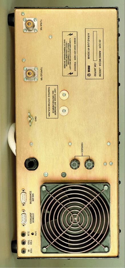
OITAA2000
Jun 21, 1999ACOM2000A Automatic HF Linear Amplifier
Equipment Class
AMP - Amplifier