OITAA2000ACOM2000A Automatic HF Linear Amplifier
ACOM International, Inc.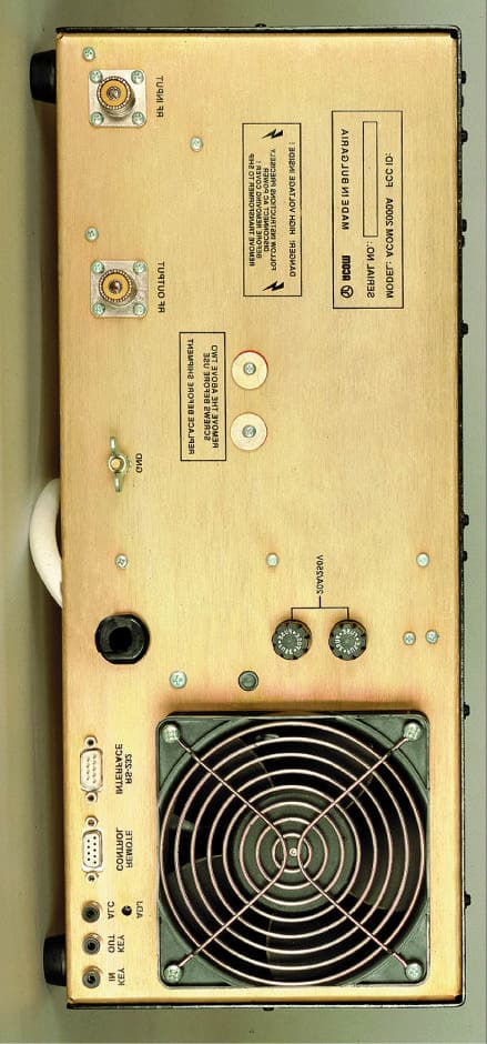
Click to zoom
Application Details
- Equipment Class
- AMP - Amplifier
- Date of Grant
- Jun 21, 1999
- Application Purpose
- Original Equipment
- Date of Application
- Apr 11, 1999
- Equipment Note
- ACOM2000A Automatic HF Linear Amplifier
- Frequency Range
- 1.80000000 - 21.45000000
- Company
- ACOM International, Inc.
- Country
- United States
Documents & Files
Document Text
Text extracted from the exhibit documents filed with the FCC. Open a document above to read the original.
Users Manual
International, Inc. Exhibit 7: User’s Manual External Radio Frequency Power Amplifier ACOM 2000A Model 2000A 157 Horse Pond Road, Sudbury, MA 01776 Tel: (978) 440-7555 Fax: (978) 440-9080 e-mail: [email protected] 1 Table of Contents 1. GENERAL INFORMATION . . . . . . . . . . . . . . . . . . . . . . . . . . . . . . . . . . .3 1-1. Introduction and Description . . . . . . . . . . . . . . . . . . . . . . . . . . . . . . . . . . . . .3 1-2. Owner Assistance . . . . . . . . . . . . . . . . . . . . . . . . . . . . . . . . . . . . . . . . . . . . . .3 1-3. Equipment Supplied and Options . . . . . . . . . . . . . . . . . . . . . . . . . . . . . . . . . .3 1-4. Features . . . . . . . . . . . . . . . . . . . . . . . . . . . . . . . . . . . . . . . . . . . . . . . . . . . . . .3 1-5. Safety Considerations, Explicit Definitions . . . . . . . . . . . . . . . . . . . . . . . . . . .4 2. INSTALLATION . . . . . . . . . . . . . . . . . . . . . . . . . . . . . . . . . . . . . . . . . . .6 2-1. Unpacking and Initial Inspection . . . . . . . . . . . . . . . . . . . . . . . . . . . . . . . . . . .6 2-2. Line Voltage Selection . . . . . . . . . . . . . . . . . . . . . . . . . . . . . . . . . . . . . . . . . . .6 2-3. Transformer Installation . . . . . . . . . . . . . . . . . . . . . . . . . . . . . . . . . . . . . . . . . .7 2-4. Connections . . . . . . . . . . . . . . . . . . . . . . . . . . . . . . . . . . . . . . . . . . . . . . . . . .8 2-5. Installation of Optional Fan . . . . . . . . . . . . . . . . . . . . . . . . . . . . . . . . . . . . . .10 3. POWER ON, RCU CONTROLS, INDICATORS AND MENUS . . . . . .11 4. MAIN MENU, FREQUENCY AND ANTENNA SELECTION . . . . . . .13 4-1. AUTO TUNE sub-menu . . . . . . . . . . . . . . . . . . . . . . . . . . . . . . . . . . . . . . . .16 4-2. MANUAL TUNE sub-menu . . . . . . . . . . . . . . . . . . . . . . . . . . . . . . . . . . . . .18 4-3. MEASURE sub-menu . . . . . . . . . . . . . . . . . . . . . . . . . . . . . . . . . . . . . . . . . . .18 4-4. SERVICE sub-menu . . . . . . . . . . . . . . . . . . . . . . . . . . . . . . . . . . . . . . . . . . . .19 4-5. Erasing USR segments (return to DEF- tunings) . . . . . . . . . . . . . . . . . . . . .20 5. OFF-MENU . . . . . . . . . . . . . . . . . . . . . . . . . . . . . . . . . . . . . . . . . . . . . .20 5-1. HELP . . . . . . . . . . . . . . . . . . . . . . . . . . . . . . . . . . . . . . . . . . . . . . . . . . . . . . .20 5-2. CALL . . . . . . . . . . . . . . . . . . . . . . . . . . . . . . . . . . . . . . . . . . . . . . . . . . . . . . .20 5-3. INFO (INFO BOX) . . . . . . . . . . . . . . . . . . . . . . . . . . . . . . . . . . . . . . . . . . . .21 5-4. LOCK . . . . . . . . . . . . . . . . . . . . . . . . . . . . . . . . . . . . . . . . . . . . . . . . . . . . . . .21 2 5-5. CLR . . . . . . . . . . . . . . . . . . . . . . . . . . . . . . . . . . . . . . . . . . . . . . . . . . . . . . . .22 5-6. DEF (Defaults) . . . . . . . . . . . . . . . . . . . . . . . . . . . . . . . . . . . . . . . . . . . . . . . .22 5-7. Erasing Nonvolatile Memory . . . . . . . . . . . . . . . . . . . . . . . . . . . . . . . . . . . . .23 6. MAINTENANCE . . . . . . . . . . . . . . . . . . . . . . . . . . . . . . . . . . . . . . . . . .24 6-1. Cleaning . . . . . . . . . . . . . . . . . . . . . . . . . . . . . . . . . . . . . . . . . . . . . . . . . . . . .24 6-2. Backup Battery Replacement . . . . . . . . . . . . . . . . . . . . . . . . . . . . . . . . . . . .24 6-3. Fuses Replacement . . . . . . . . . . . . . . . . . . . . . . . . . . . . . . . . . . . . . . . . . . . .25 6-4. Tubes Replacement . . . . . . . . . . . . . . . . . . . . . . . . . . . . . . . . . . . . . . . . . . . .25 6-5. The ACOM2000A Simplified Schematic Diagram . . . . . . . . . . . . . . . . . . . . .25 6-6. Troubleshooting . . . . . . . . . . . . . . . . . . . . . . . . . . . . . . . . . . . . . . . . . . . . . . .26 7. SPECIFICATIONS . . . . . . . . . . . . . . . . . . . . . . . . . . . . . . . . . . . . . . . . .29 7-1. Parameters . . . . . . . . . . . . . . . . . . . . . . . . . . . . . . . . . . . . . . . . . . . . . . . . . .29 7-2. Functions . . . . . . . . . . . . . . . . . . . . . . . . . . . . . . . . . . . . . . . . . . . . . . . . . . . .30 7-3. Storage and Shipment . . . . . . . . . . . . . . . . . . . . . . . . . . . . . . . . . . . . . . . . . .31 8. BRIEF MENU GUIDE . . . . . . . . . . . . . . . . . . . . . . . . . . . . . . . . . . . . . .32 9. ACOM WARRANTY . . . . . . . . . . . . . . . . . . . . . . . . . . . . . . . . . . . . . . .32 3 1. GENERAL INFORMATION 1-1. Introduction and Description This manual explains the installation, operation and maintenance of the ACOM2000A automatic HF linear amplifier. The ACOM2000A is a complete and self-contained linear amplifier which covers all amateur bands from 1.8 through 30MHz, has automatic self-tune capability, and provides up to 1500W output power with less than 60W exciter drive. In addition, it has automatic antenna impedance matching capability for loads up to 3:1 VSWR (2:1 on 160 meters). It features a Remote Control Unit (RCU), contains nonvolatile memory for settings on up to ten different antennas per frequency segment, and offers command capability for use with an external automatic antenna selector and/or automatic antenna tuner. Transmit / receive switching is capable of full break-in operation (QSK) via an internal vacuum relay. All indicators and controls (except the primary mains switch and indicator) are available via the RCU. All command input to the RCU is menu-driven. 1-2. Owner Assistance If assistance is needed, you should contact your local dealer first. If you still have an issue you need to discuss with one of ACOM's specialists. The contact information is as follows: fax + 359 2 276 190, e- mail [email protected] or by mail: ul.3011-9, complex Lyulin, 1336 Sofia, Bulgaria. 1-3. Equipment Supplied and Options The ACOM 2000A amplifier is shipped in two cardboard cartons. One carton contains the po…
Text truncated - open the document above for the full version.
Attestation Statements
Exhibit 11Page 1 of 5 International, Inc. Exhibit 11: Additional Information in Response to 47 CFR Ch1. 1 Sec. 2.1033 External Radio Frequency Power Amplifier ACOM 2000A Model 2000A 157 Horse Pond Road, Sudbury, MA 01776 Tel: (978) 440-7555 Fax: (978) 440-9080 e-mail: [email protected] Exhibit 11Page 2 of 5 Section c.1. The "ACOM2000A" will be assembled and production testing performed in the Republic of Bulgaria by the private company "ACOM, OOD". ACOM, OOD has designed and manufactured external radio power amplifiers for amateur use since 1990. The company presently manufacturers the Alpha 91B HF Linear Amplifier, FCC ID:DGVPA-91B , marketed in the United States by Alpha/Power, Inc. of Colorado Springs, Colorado. ACOM, OOD is located at Lulin Complex, 3011 Street #9, 1324 Sofia, Bulgaria. The president and principal owner of ACOM, OOD is Mr. Vassil M. Vassilev. No FCC manufacturer code has previously been assigned to ACOM, OOD. Applicant for certification, ACOM International, Inc. is the exclusive distributor of ACOM, OOD products in North America. With respect to the subject "ACOM2000A" equipment, Applicant is responsible for compliance with FCC rules. ACOM International is located at 157 Horse Pond Road, Sudbury, Massachusetts, USA 01776. No FCC manufacturer code has previously been assigned to ACOM International, Inc. Applicant has conducted or observed all design-proof testing and will re-test samples of production equipment on an ongoing basis to assure conformance to Applicant's quality standards, including all FCC regulatory requirements. Section c.2 This product, designated "ACOM2000A Automatic HF Linear Amplifier," hereafter "ACOM2000A," is a 1.5 kW external radio frequency power amplifier. The ACOM2000A will be marketed in the United States for use in the Amateur Radio Service. The FCC identifier for the ACOM2000A will be: OITAA2000 Exhibit 11Page 3 of 5 Section c.3 A copy of the Installation and Operating Instructions for the ACOM2000A is included as Exhibit 7. Section c.4 The equipment is suitable for all types of emission authorized for amateur HF use in 97.305 of the FCC rules. Section c.5 The equipment is designed to meet all specifications and FCC performance standards on authorized amateur bands from 1.8 to 29.7 MHz. When delivered to any buyer within FCC's jurisdiction, the equipment is operable on amateur bands only from 1.8 through 21.450 MHz. Means by which FCC 97.317(b) is met are described in Exhibit 12. Section c.6 The equipment can be operated at any power level up to 1,500 Watts. Operation at lower power levels is possible by reducing the RF excitation level. The ACOM 2000A provides a peak-reading LED bar graph for monitoring output power levels. Section c.7 The equipment is rated for and limited to maximum RF power output of 1,500 Watts, as provided in Part 97 of the FCC rules. Section c.8 Nominal voltages and currents at rated output are: DC plate voltage – 2300 volts DC plate current - 1.0 Ampere DC screen voltage - 340 volts DC grid bias - -55 volts Exhibit 11Page 4 of 5 Section c.9 The equipment utilizes a microprocessor-driven automatic tuning circuit on all radio amateur frequencies. Input excitation is applied to a level of 10 to 20 Watts, as measured by the internal power sensing circuit. When the input level is within this range, the automatic tuning circuit is activated. The tuning algorithm coded in the microprocessor ensures that a proper match is obtained with antenna loads presenting VSWR as high as 3:1. Section c.10 Several features of the ACOM2000A design are specifically intended to reduce spurious radiation to a minimum. In the input circuit, a non-inductive resistor load ensures that VSWR of 1.2:1 or less is presented to the exciter at the RF input terminal over the entire frequency range and up to the maximum input power. The output circuit comprises a classic Pi-L network, which suppresses the harmonic emissions. The ACOM2000A incorporates an output power sensing circuit and ALC, which limits the amplifier output power to 1.5kW. Schematic diagrams of the input and output matching circuits and power limiting circuits are included in Exhibit 4. Section c.11 A photograph showing the design of the FCC identification label for the ACOM2000A is included as Exhibit 1. Section c.12 Photographs showing the construction and layout of the ACOM2000A are included as Exhibits 2 and 9. Exhibit 11Page 5 of 5 Section c.13 Not applicable to external power amplifier. Section c.14 Not applicable, as provided in Section c.15. Section c.15 Measurement data indicating compliance with requirements of Part 97.307 and Part 97.317 is included as Exhibit 5. Section c.16 Not applicable to external RF power amplifier. Section c.17 Not applicable to external RF power amplifier. The subject equipment application is not part of a composite system.
Block Diagram
Exhibit 3Page 1 of 2 International, Inc. Exhibit 3: Block Diagram External Radio Frequency Power Amplifier ACOM 2000A Model 2000A 157 Horse Pond Road, Sudbury, MA 01776 Tel: (978) 440-7555 Fax: (978) 440-9080 e-mail: [email protected] Exhibit 3Page 2 of 2
External Photos
Exhibit 2Page 1 of 3 International, Inc. Exhibit 2: External Photos External Radio Frequency Power Amplifier ACOM 2000A Model 2000A 157 Horse Pond Road, Sudbury, MA 01776 Tel: (978) 440-7555 Fax: (978) 440-9080 e-mail: [email protected] Exhibit 2Page 2 of 3 Exhibit 2Page 3 of 3
ID Label/Location Info
Exhibit 1Page 1 of 4 International, Inc. Exhibit 1: ID Label Location Info External Radio Frequency Power Amplifier ACOM 2000A Model 2000A 157 Horse Pond Road, Sudbury, MA 01776 Tel: (978) 440-7555 Fax: (978) 440-9080 e-mail: [email protected] Exhibit 1Page 2 of 4 FCC ID and Label Location Information In compliance with FCC Regulation 47 CFR Ch. 1 part 2.925, the ACOM 2000A, External Radio Frequency Power Amplifier, Model 2000A bears a label located on the rear plate of the equipment which displays the following FCC Identifier: Part (a) 1. The term FCC ID followed by the three digit Grantee Code and the six digit Equipment Product Code. 2. Not applicable. 3. Not applicable. Part (b) Not applicable Part (c) Reserved Part (d) 1. The ACOM 2000A label is indelibly printed on the rear panel of the equipment. This label will last the lifetime of the equipment in the environment in which the equipment will be operated and is not readily detachable. 2. The ACOM 2000A label is readily visible on the outside of the equipment enclosure. Part (e) Not applicable Part (f) 1. The size of the label is 3.50 by 1.25 inches. The actual label and their location on the equipment are shown in the following pictures. Exhibit 1Page 3 of 4 Exhibit 1Page 4 of 4 In the Serial No., the X’s represent the serialized units in order of manufacture. For example, the first unit will be Serial No. 980001 and the 256 th unit will be Serial No. 980256. In the FCC ID # Grantee code is: OIT and the AA 2000 portion is the equipment product code.
Internal Photos
Exhibit 9Page 1 of 5 International, Inc. Exhibit 9: Internal Photos External Radio Frequency Power Amplifier ACOM 2000A Model 2000A 157 Horse Pond Road, Sudbury, MA 01776 Tel: (978) 440-7555 Fax: (978) 440-9080 e-mail: [email protected] Exhibit 9Page 2 of 5 Exhibit 9Page 3 of 5 Exhibit 9Page 4 of 5 Exhibit 9Page 5 of 5
Operational Description
Exhibit 10Page 1 of 2 International, Inc. Exhibit 10: Operational Description External Radio Frequency Power Amplifier ACOM 2000A Model 2000A 157 Horse Pond Road, Sudbury, MA 01776 Tel: (978) 440-7555 Fax: (978) 440-9080 e-mail: [email protected] Exhibit 10Page 2 of 2 The ACOM2000A is a complete and self-contained linear amplifier which covers all amateur bands, has automatic self-tune capability, and provides up to 1500W output power with less than 60W exciter drive. In addition, it has automatic antenna impedance matching capability for loads up to 3:1 VSWR (2:1 on 160 meters). It features a Remote Control Unit (RCU), contains nonvolatile memory for settings on up to ten different antennas per frequency segment, and offers command capability for use with an external automatic antenna selector and/or automatic antenna tuner. Transmit / receive switching is capable of full break-in operation (QSK) via an internal vacuum relay. All indicators and controls (except the primary mains switch and indicator) are available via the RCU. All command input to the RCU is menu-driven. A more detailed description of the theory of operation of the amplifier can be found in section 6-5, page 25-26, of the Users Manual included as Exhibit 7.
Schematics
Exhibit 4Page 1 of 43 International, Inc. Exhibit 4: Schematics External Radio Frequency Power Amplifier ACOM 2000A Model 2000A 157 Horse Pond Road, Sudbury, MA 01776 Tel: (978) 440-7555 Fax: (978) 440-9080 e-mail: [email protected] Exhibit 4Page 2 of 43 Exhibit 4Page 3 of 43 Exhibit 4Page 4 of 43 Exhibit 4Page 5 of 43 Exhibit 4Page 6 of 43 Exhibit 4Page 7 of 43 Exhibit 4Page 8 of 43 Exhibit 4Page 9 of 43 Exhibit 4Page 10 of 43 Exhibit 4Page 11 of 43 Exhibit 4Page 12 of 43 Exhibit 4Page 13 of 43 Exhibit 4Page 14 of 43 Exhibit 4Page 15 of 43 Exhibit 4Page 16 of 43 Exhibit 4Page 17 of 43 Exhibit 4Page 18 of 43 Exhibit 4Page 19 of 43 Exhibit 4Page 20 of 43 Exhibit 4Page 21 of 43 Exhibit 4Page 22 of 43 Exhibit 4Page 23 of 43 Exhibit 4Page 24 of 43 Exhibit 4Page 25 of 43 Exhibit 4Page 26 of 43 Exhibit 4Page 27 of 43 Exhibit 4Page 28 of 43 Exhibit 4Page 29 of 43 Exhibit 4Page 30 of 43 Exhibit 4Page 31 of 43 Exhibit 4Page 32 of 43 Exhibit 4Page 33 of 43 Exhibit 4Page 34 of 43 Exhibit 4Page 35 of 43 Exhibit 4Page 36 of 43 Exhibit 4Page 37 of 43 Exhibit 4Page 38 of 43 Exhibit 4Page 39 of 43 Exhibit 4Page 40 of 43 Exhibit 4Page 41 of 43 Exhibit 4Page 42 of 43 Exhibit 4Page 43 of 43
Test Report
This report shall not be reproduced, in whole or in part without the written approval of Test Site Services Inc. This report must not be used by the recipient to claim product endorsement by NVLAP or any other agency of the U.S. Government Test Site Services. Inc. Test Report For Acom International Acom 2000A Model 2000A Emissions FCC, Part 97 Sub Part D External RF Power Amplifier Test # B90191 Test Site Services, Inc. P.O. Box 766 Marlboro, MA 01752 U.S.A. Phone/Fax: (508) 481-1684 Test Site Services, Inc.Report # B90191 Acom International03/19/99EUT: Acom 2000A Table of Contents GENERAL INFORMATION..................................................................................................................................................1 EQUIPMENT UNDER TEST DESCRIPTION.......................................................................................................................3 TEST SUMMARY..................................................................................................................................................................4 BLOCK DIAGRAM...............................................................................................................................................................5 BLOCK DIAGRAM DESCRIPTION......................................................................................................................................6 CABLE DESCRIPTION........................................................................................................................................................12 TEST EQUIPMENT LIST.....................................................................................................................................................15 APPENDIX A, TEST DATA................................................................................................................................................A1 APPENDIX B, MEASUREMENT FACILITIES INFORMATION.......................................................................................D1 Test Site Services, Inc.Report # B90191page 1 of 15 Acom International03/19/99EUT: Acom 2000A EMI Test Report for Acom International Test Number : B90191 Product Name : Acom 2000A Regulation : FCC, Part 97 Sub Part D : External RF Power Amplifier Acom International 157 Horse Pond Road Sudbury, MA 01776 Phone: 978-440-7555 Fax : 978-440-9008 This test report is not valid without the signatures of Test Site Services, Inc. personnel. Test Site Services, Inc.Report # B90191page 2 of 15 Acom International03/19/99EUT: Acom 2000A Administrative Data Regulation : FCC, Part 97 Sub Part D : External RF Power Amplifier Test Method : FCC, Part 97.317 (a) (1) (2) (3),(b) (1) (2),(c) (i) (ii) Part 97.307 (d) : Calibration / Measurements traceable to NIST Test Type : Qualification Responsible Parties Manufacturer : Acom OOD - Bulgaria Applicant : Acom International Inc. USA EUT Type/Model # : Linear Amplifier / 2000A Date(s) of Test : 03/19/99 Customer Personnel : Krassimir PetkovPresident TSS Personnel : R. WiedemanEMC Engineer : Tom Charron : Ken Raymond Test Engineer Test Engineer Test Location: Open Area Test Site Test Site Services, Inc. 30 Birch St. Milford, MA 01757 U.S.A. NOTICE: FCC Rule 2.955 requires that a Verification Report for a Class A Computing Device must be signed by "an Official of the Company responsible for the device". A signature block has been provided on the first page for this purpose. Test Site Services, Inc.Report # B90191page 3 of 15 Acom International03/19/99EUT: Acom 2000A EUT Description The EUT (Acom 2000A) is a Linear Amplifier for Amateur Radio. A complete description of the EUT may be found on block identifier page one. The tests were run in a typical configuration including the following support equipment; 1)H.F. Transceiver 2)Drake Watt Meter 3)Bird Watt Meter 4)Bird 1.5KW 30db Attenuater 5)Band Pass Filters REASON FOR TEST: Qualification for FCC Part 97 CHANGES MADE DURING TEST: None DEVIATIONS FROM STANDARD TEST METHOD: None Test Site Services, Inc.Report # B90191page 4 of 15 Acom International03/19/99EUT: Acom 2000A Test Summary The Acom 2000A complied with FCC Part 97 Subpart D, 97.307 and 97.317 Limits for Amatuer Radio equipment when tested in the system configuration defined herein. The following table indicates the margins (i.e. difference between measurement point and limit) of the nine data points and their harmonics to the tenth order: Results reflect amplifier as shipped with 24 and 28 MHz. Bands disabled Power Gain 97.317 (a) (1) (2) (3),(c) (6) (ii)Spurious emissions 97.307 (d) Frequency (Mhz.) f1 Power in (W) Power out (W) Gain dB2f1 dBc3f1 dBc4f1 dBc5-10f1 dBc 1.9501500.0014.70-51.50-78.60>-78.00>-78.00 3.75501500.0014.70-52.40-77.90-78.00>-78.00 7.15501500.0014.70-56.50>-78.00>-78.00>-78.00 10.125511500.0014.68-53.30>-78.00>-78.00>-78.00 14.175501500.0014.70-55.10-77.60>-77.00>-77.00 18.118531500.0014.51-62.40>-75.00>-75.00>-75.00 21.22552.51500.0014.55-61.40-76.00>-76.00>-76.00 97.317 (b) (1) (2) 0 dB gain was noted in the 12 & 10 meter amateur bands and measured at the points below 24.9450.050.00.0 28.9050.050.00.0 97.317 (c) (6) (i) was not capable of full power output when driven with < 40 watts 1.938.00800.0013.2 3.7538.00900.0013.7 7.1538.00900.0013.7 10.12538.00900.0013.7 14.17538.00850.0013.5 18.11838.00800.0013.2 21.22538.00800.0013.2 See Data Section For Additional Detail. Test Site Services, Inc.Report # B90191page 5 of 15 Acom International03/19/99EUT: Acom 2000A Block Diagram for Acom 2000A C1(PS) G1(DS) D1(CX) E1(CX) E2(CX) A1(PU) E3(CX)B1(PU) 30db Pad F1(CX) D2(CX) Shield Room Control Room F2(CX) PS = Power Cord Shielded DS = Data Cable Shielded CX = Coaxial Cable PU = Power Cord Unshielded DS = Data Cable Shielded FL = Fiber Link = Connector 20db Pad Bird 1.5KW 30db Attenuator 5 Bird Watt Meter 4 EUT 1 Acom 2000 A Filter 6 Drake Watt Meter 3 2 ICOM IC 761 Tranceiver C.W.Key Hewlett Packard Spectrum Analyz…
Text truncated - open the document above for the full version.
Test Report
Exhibit 12Page 1 of 3 International, Inc. Exhibit 12: Measurements Demonstrating Conformance to 97.307 and 97.317 External Radio Frequency Power Amplifier ACOM 2000A Model 2000A 157 Horse Pond Road, Sudbury, MA 01776 Tel: (978) 440-7555 Fax: (978) 440-9080 e-mail: [email protected] Exhibit 12Page 2 of 3 97.317(a)(1)&(3) & 97.317(b): Spurious Emissions per 97.307(d) and Gain versus Frequency Amplifier under test operated at frequencies f1 with CW (A1A) excitation. Spectrum analyzer used to observe all frequencies from f1 through at least 10 x f1 for harmonic and spurious emissions. Results reflect amplifier as shipped with 24 and 28 MHz Bands disabled Power Gain 97.317 (a) (1) (2) (3), (c) (6) (ii)Spurious emissions 97.307 (d) Frequency (MHz) f 1 Power in (W) Power out (W) Gain dB2f1 dBc3f1 dBc4f1 dBc5-10f1 dBc 1.90050150014.70-51.50-78.60>-78.00>-78.00 3.75050150014.70-52.40-77.90>-78.00>-78.00 7.15050150014.70-56.50>-78.00>-78.00>-78.00 10.12551150014.68-53.30>-78.00>-78.00>-78.00 14.17550150014.70-55.10-77.60>-77.00>-77.00 18.11853150014.51-62.40>-75.00>-75.00>-75.00 21.22552.5150014.55-61.40-76.00>-76.00>-76.00 97.317 (b) (1) (2) 0 dB gain was noted in the 12 & 10 meter amateur bands and measured at the points below 24.94050500.0 28.90050500.0 97.317 (c) (6) (i) was not capable of full power output when driven with <40 watts 1.93880013.2 3.753890013.7 7.1503890013.7 10.1253890013.7 14.1753885013.5 18.1183880013.2 21.2253880013.2 After owner modification to activate 24-28 MHz bands: Frequency (MHz) f 1 Power in (W) Power out (W) Gain dB2f1 dBc3f1 dBc 24.940*56150014.3-55.00>-70 28.900*50150014.8-54.00>-70 *Not usable as shipped; data applicable only after enabling of 24 & 28 MHz bands as follows. When delivered to any buyer located within the FCC’s jurisdiction, the equipment is operable on authorized amateur bands only from 1.8 through 21.45 MHz. To meet the requirements of 97.317(b), the equipment employs a digital electronic lock-out system which disables the amplifier when the RF excitation frequency exceeds 21.45 MHz. Operation on the 24 and 28 MHz amateur bands in full conformance with FCC rules only by amateurs whose FCC licenses authorize such operation is possible after such owners make a simple but subtle modification – cutting the lead on one resistor on the digital control module. ACOM International advises an owner how to perform this modification ONLY after receiving proof that he holds an appropriate FCC license. This is the FCC-approved process that has been adopted industry-wide to ensure that amateur amplifiers are used in conformance with FCC rules. Exhibit 12Page 3 of 3 97.307(a)(b): Intermodulation & Linearity Exciter operating in SSB (A3E, J3E) mode with two-equal-tone audio applied to the microphone input. Amplifier under test driven to 1.5 kW PEP output at center of each amateur band, approximately 50 W PEP excitation. Intermodulation in dB relative to 1.5 kW PEP: Order:D3D5D7D9D11 Frequency (MHz) dBdBdBdBdB 1.900-40-48-48-52-55 3.750-43-47-48-52-55 7.150-41-44-48-53-52 10.125-42-42-48-54-51 14.175-43-43-48-58-55 18.118-45-46-49-55-53 21.225-45-46-52-56-54 24.940*-43-46-50-56-54 28.900*-42-46-50-55-53 Worst Case-40-46-48-52-53 *Not usable as shipped; data applicable only after authorized owner modification. 97.317(a)(2)&(3): When the amplifier is in the “standby” or “off” positions, but still connected to the exciter, no measurable change from the normal output of the exciter is detectable with the spectrum analyzer (noise floor approximately –70dBc) when amplifier is driven with 0 to 150 W mean RF power. 97.317(c): The amplifier possesses none of the prohibited characteristics listed in this section. 97.317(c)(6)(iii): The amplifier gain does not exceed 15 dB for any level of input signal. 97.317(c)(6)(iv): The amplifier is capable of greater than 50% duty cycle at rated power output with A1A, A3E(J3E), or F1B,F3E J3F emission. 97.317(c)(7): Amplifier gain is established principally by RF negative feedback in the cathode circuit. The input swamping resistor is used only to present a 50 ohm load to the broadband grid matching circuit, not as an attenuator. Removal of this resistor or changing its value will result in a severe load mismatch to the exciter output. Additional data: Information and data supplied by tube manufacturer SVETLANA concerning the GU74B/4CX800A tetrode is available by request from the manufacturer.
Test Setup Photos
This report shall not be reproduced, in whole or in part without the written approval of Test Site Services Inc. This report must not be used by the recipient to claim product endorsement by NVLAP or any other agency of the U.S. Government Test Site Services. Inc. Test Report Photographs For Acom International Acom 2000A Model 2000A Emissions FCC, Part 97 Sub Part D External RF Power Amplifier Test # B90191 Test Site Services, Inc. P.O. Box 766 Marlboro, MA 01752 U.S.A. Phone/Fax: (508) 481-1684 Test Site Services, Inc.Report # B90191 Acom International03/19/99EUT: Acom 2000A TEST PHOTOGRAPHS Test Site Services, Inc.Report # B90191 Acom International03/19/99EUT: Acom 2000A TEST PHOTOGRAPHS Test Site Services, Inc.Report # B90191 Acom International03/19/99EUT: Acom 2000A TEST PHOTOGRAPHS Test Site Services, Inc.Report # B90191 Acom International03/19/99EUT: Acom 2000A TEST PHOTOGRAPHS XCVR Frequency 28.90 – ACOM 2000A Frequency Violation Test Site Services, Inc.Report # B90191 Acom International03/19/99EUT: Acom 2000A TEST PHOTOGRAPHS XCVR Frequency 24.94 – ACOM 2000A Frequency Violation Test Site Services, Inc.Report # B90191 Acom International03/19/99EUT: Acom 2000A
Contact Information
Applicant
Krassimir D Petkov(President)
Test Firm
Test Site Services Co.Lawrence Lee
Technical Specifications
| # | Rule Parts | Frequency Range | Power Output | Emission | Tolerance |
|---|---|---|---|---|---|
| 3 | 97 | 1.8 MHz - 21.45 MHz | 1500 W | J3E | Amp |
Other Applications from ACOM International, Inc.
OITAA1000
Dec 12, 2000ACOM 1000 HF Liner Ampifier
Equipment Class
AMP - Amplifier