OJS990001Electronic Lock Receiver
Micro Enhanced Technology, Inc.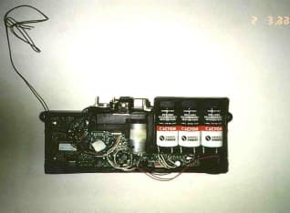
Click to zoom
Application Details
- Equipment Class
- CYY - Communications Receiver used w/Pt 15 Transmitter
- Date of Grant
- Aug 10, 1999
- Application Purpose
- Original Equipment
- Date of Application
- May 03, 1999
- Equipment Note
- Electronic Lock Receiver
- Frequency Range
- 418.00000000 - 418.00000000
- Country
- United States
Documents & Files
Document Text
Text extracted from the exhibit documents filed with the FCC. Open a document above to read the original.
Block Diagram
Page 1 of 1 FCC ID: OJS990001 Block Diagrams of EUT
Cover Letter(s)
Page 1 of 1 FCC ID: OJS990001 & OJS990002 Letter of Authorization
External Photos
Page 1 of 1 FCC ID: OJS990001 External Photographs of EUT External Front External Rear External Power supply
ID Label/Location Info
Page 1 of 1 FCC ID: OJS990001 FCC ID Label The label is 0.937 x 2.0 inches with V23 permanent acrylic adhesive. The material is white 50-lb. paper with black printing. FCC Label Not to scale FCC ID: OJS 990001 This device complies with Part of the FCC Rules. Operation is subject to the following two conditions: (1) This dvice may not cause harmful interference, and (2) this device accept any interference received including interference that may cause undesired operation.
Internal Photos
Page 1 of 4 FCC ID: OJS990001 Internal Photographs of EUT PCB Component Page 2 of 4 FCC ID: OJS990001 Internal Photographs of EUT PCB Foil Page 3 of 4 FCC ID: OJS990001 Internal Photographs of EUT Page 4 of 4 FCC ID: XXXXX Internal Photographs of EUT Power supply PCB Component Power Supply PCB Foil
Operational Description
Page 1 of 1 FCC ID: OJS990001 & OJS990002 Product Description Keyless Entry System Using Radio Frequency Transmit and Receiver Electronics MET has developed a keyless entry system using a radio frequency transmitter and receiver. The transmitter will transmit a 418 MHz OOK On-Off keying) signal to the receiver. The signal transmitted a digital encrypted using a Keeloq TM rolling code algorithm at a 400 microsecond per bit baud rate, 61 bits per code. The receiver will receive the 418 MHz signal and decode the digital signal using the same Keeloq algorithm. The 3 possible signals that will be decoded by the receiver are unlock, lock, and enable/disable alarm. The microcomputer electronics at the receiver will proceed to perform the requested access control functions. The expected distance from the transmitter to the receiver is a 30-foot range.
Schematics
RX1300 418.0 MHz ASH Receiver RF Monolithics, Inc.Phone: (972) 233-2903Fax: (972) 387-8148E-mail: [email protected] 1 of 4 RFM Europe SalesPhone: (33-0) (1) 39.16.42.89Fax: (33-0) (1) 39.16.42.70http://www.rfm.com ©1998 by RF Monolithics, Inc. The stylized RFM logo and RFM are registered trademarks of RF Monolithics, Inc.RX1300-A-041798 •Ideal for 418.0 MHz, 3 V Data Receivers in the UK and the USA •High-Sensitivity Passive Design with No RF Oscillation •Baseband Data Rate of 2400 b/s •Simple to Apply with External Parts Count •Rugged, Surface-Mount Package with 130 mm 2 Footprint This amplifier-sequenced hybrid (ASH) receiver is based on several leading-edge technologies that allow outstanding performance in a small and simple-to-apply module. Two surface-accoustic-wave (SAW) devices are employed. Front-end fil- tering by a low-loss coupled-resonator SAW filter provides excellent selectivity. Typical sensitivity better than -100 dBm is achieved with no RF oscillating or regenerative circuits. This results in virtually no RF spu- rious emissions. A low-loss SAW delay line provides the time delay necessary to sequence the two RF amplifiers. Time sequencing of the RF gain eliminates the need for frequency conversion prior to AM detection. This receiver is designed to operate from a 3 V lithium battery with typically 1.1 mA current. For system design flexibility, the baseband output is accessible, and the comparator threshold can be changed externally between two settings. Typical applications include unlicensed wireless remote-controls, security and data-trans- mission devices operating in the United Kingdom under DTI MPT 1340 and in the USA under FCC Part 15. Electrical Characteristics CharacteristicSymNotesMinimumTypicalMaximumUnits Operating Radio Frequencyf C 2, 3418.0 NominalMHz Received Carrier Modulation Type4, 5Pulse Modulation (OOK) RF BandSensitivity 6 -100 dBm Operating Signal Strength-10 Channel Widthf C ±200kHz Input ImpedanceZ IN 50 NominalW Interference RejectionHalf-Frequency Spurious 7 105 dB f C ± 1 MHz 20 Sequencing (Sampling)Sample Duration 8 700ns Sample Repetition Rate250kHz Baseband Data Rate 9 2.4kb/s 3 dB Bandwidth12kHz Comparator ThresholdDefault (Terminal 5 NC) 10 25 mV Override (Terminal 5 LOW) 0 Digital OutputCMOS Load Capacitance 11 10 p F Output HIGH VoltageV OH V CC -0.2V CC V Output LOW VoltageV OL 0.00.2 Rise Timet R 9 μs Fall Timet F 9 Power SupplyOperating VoltageV CC 1 2.73.03.5VDC Current at 25C and 3.0 VI CC 1.11.25mA Operating Ambient TemperatureT A 1-40+85°C Lid Symbolization (in addition to Lot and/or Date Codes) RFM RX1300 SM-10 Case The RX Series SMT Hybrid ASH Receivers RF Monolithics, Inc.Phone: (972) 233-2903Fax: (972) 387-8148E-mail: [email protected] 2 of 4 RFM Europe SalesPhone: (33-0) (1) 39.16.42.89Fax: (33-0) (1) 39.16.42.70http://www.rfm.com ©1998 by RF Monolithics, Inc. The stylized RFM logo and RFM are registered trademarks of RF Monolithics, Inc.RX1300-A-041798 CAUTION: Electrostatic Sensitive Device. Observe precautions for handling. Notes: 1.Unless noted otherwise, specifications apply over the entire specified operating temperature and voltage ranges. 2.One or more of the following United States patents apply: 4,454,488; 4,616,197; 4,749,964; 4,902,925. Other patents are pending. 3.Typically, equipment utilizing this device requires emissions testing and government approval, which is the responsibility of the equipment manufacturer. 4.The design, manufacturing process, and specifications of this device are subject to change without notice. 5.A variety of on-off-keyed (OOK) pulse modulation schemes are possible since digital decoding is an external function (not included in the ASH receiver). 6.These parameters apply over the absolute minimum operating passband which is referenced to f C . 7.With interfering signal matched to the receiver modulation and code. See “Typical Modulated Interference Rejection” for a more detailed view. 8.Sample repetition rates greater than 1 MHz are available in custom versions. Contact RFM for details. 9.Baseband bandwidths and data rates are available to 140 kHz and 56 kHz, respectively, in custom versions. Contact RFM for details. 10.The default comparator threshold (with terminal 5 not connected) is optimized for low duty-cycle, or “bursty” data and eliminates noise output when there is no RF signal. The override threshold (with terminal 5 connected to ground) is optimized for continuous data. 11.The ASH receiver is designed to drive a single CMOS load 12.For ESD protection.. Block Diagram and Electrical Connections Absolute Maximum Ratings RatingValueUnits Incident RF Power+10dBm Power Supply Voltage (V CC to Ground) (Observe ESD Precautions)-0.3 to +4.0VDC ESD (100 pF, 1.5 kW)Terminals 2, 3, or 7 to Ground±2000 V All Other Terminals to Ground±300 Case Temperature 1 -40 to +100°C T o p V i e w 50 ohm Antenna +3V 10 uF 0.1 to 10 uF 1 uF Pulse Gen- erator SAW Delay Line LPF RF Amp. RF Amp. SAW BPF Comparator AM Detector 109876 54321 RF InputGndGndData Output Voltage Reference Vcc Baseband Output Comparator Input Gnd Threshold Override Note 12 The RX Series SMT Hybrid ASH Receivers RF Monolithics, Inc.Phone: (972) 233-2903Fax: (972) 387-8148E-mail: [email protected] 3 of 4 RFM Europe SalesPhone: (33-0) (1) 39.16.42.89Fax: (33-0) (1) 39.16.42.70http://www.rfm.com ©1998 by RF Monolithics, Inc. The stylized RFM logo and RFM are registered trademarks of RF Monolithics, Inc.RX1300-A-041798 Demonstration Circuit Typical Modulated Interference Rejection (433.92 MHz RX1000 Shown) This plot is for an interfacing signal modulated with the receiver’s modulation and code. Continuous wave (CW) or signals with other modulation or codes typically result in significantly better rejection performance. ++ 1 2 3 4 5 6 7 8 9 10 11 12 13 14 15 16 + Piezo Alarm 620 K 0.1 uF 33 K 0.1 uF 1 mA @ 3VDC RS 273-065A or equiv + + + +3V Lithium CR2032 1 uF OPEN: Default 25mV CLOSED: Override OV .1 to 1uF 10 uF 1 Vcc 2 BB Out 3 Comp I…
Text truncated - open the document above for the full version.
Test Report
Nursery Monitor Receiver Radiometrics Midwest Corporation Test Document RP-3997R Issue Date: May 7, 1999 This report concerns: Original grant Equipment type: 418MHz receiver Transition Rules per 15.37 are not requested. Tests Performed ForTest Facility Micro Enhanced Technology, Inc. 100 w. Plainfield Rd., Suite 202 Countryside, Illinois 60525 Radiometrics Midwest Corporation 12 East Devonwood Romeoville, IL 60446 Phone: (815) 293-0772 FAX: (815) 293-0820 [email protected] Test Report Written ByTest Report Approved By Joseph Strzelecki Senior EMC Engineer NARTE EMC-000877-NE Chris W. Carlson Director of Engineering NARTE EMC-000921-NE MEASUREMENT/TECHNICAL REPORT Micro Enhanced Technology, Inc. Model 990001 FCC ID: OJS990001 APPLICATION FOR CERTIFICATION RF Emission Measurements Performed For Determination of Compliance with the US Code of Federal Regulations Title 47, Chapter I, FCC Part 15 As Required for Certification for Unintentional Radiators Tests Performed ForFCC IDRadiometrics Test DocumentPage Micro Enhanced Technology, Inc. OJS990001RP-3997R2 of 8 Table of Contents 1.0 General Information ........................................................................................................... 3 1.1 Product Description ........................................................................................................3 1.2 Related Submittals .........................................................................................................3 1.3 Tested System Details.................................................................................................... 3 1.4 Test Methodology ...........................................................................................................3 1.5 Test Facility .................................................................................................................... 3 1.6 Test Equipment ..............................................................................................................4 2.0 System Test Configuration ................................................................................................ 4 2.1 Test System and Justification......................................................................................... 4 2.2 EUT Test Configuration .....................................................................................................4 2.3 Special Accessories ....................................................................................................... 4 2.4 Equipment Modifications ................................................................................................ 4 Figure 2.1 Configuration of Tested System .......................................................................... 5 4.0 Radiated Emissions Data .................................................................................................. 6 4.1 Field Strength Calculation..................................................................................................7 5.0 Conducted Emission Data ................................................................................................. 8 Notice: This report must not be reproduced (except in full) without the written approval of Radiometrics Midwest Corporation. Tests Performed ForFCC IDRadiometrics Test DocumentPage Micro Enhanced Technology, Inc. OJS990001RP-3997R3 of 8 1.0 General Information 1.1 Product Description The Model 990001 (referred to as the EUT in this report) is a 418 MHz Receiver. The EUT is manufactured by Micro Enhanced Technology, Inc. 1.2 Related Submittals The associated transmitter is operated under FCC 15.231. It is subject to the FCC requirements pursuant to the Certification equipment authorization under Part 15 Subpart C, and is being submitted as FCC ID: OJS990002. 1.3 Tested System Details The FCC ID's for all equipment, plus descriptions of all cables used in the tested system which have grants, are: Model Number Serial NumberFCC ID Manufacturer & Description Cable Descriptions M/N: 990001 (EUT) OJS990001Micro Enhanced Tech, Inc. Receiver Power (1.8m, US) to X-former RJ45 (1.5m, US) Keypad Antenna (0.8m, US) single wire LED indicator (0.5, US) Note: SH = Shielded; US = Unshielded; m = Cable Length in Meters, 1.4 Test Methodology The test procedures used are in accordance with the ANSI document C63.4-1992, (July 17, 1992) "Methods of Measurement of Radio Noise Emissions from Low-Voltage Electrical and Electronic Equipment in the Range of 9 kHz to 40 GHz". The specific procedures are described herein. Radiated testing was performed at an antenna to EUT distance of 3 meters. The antenna was raised and lowered from 1 to 4 meters. 1.5 Test Facility The open area test site used to collect the radiated data is located on 8625 Helmar Road in Newark, Illinois. The open field test site has a metal ground screen. Details of the site characteristics are on file with the FCC. Conducted emission measurements and preliminary radiated emission scans were performed in shielded enclosure “B” at Radiometrics' Romeoville, Illinois EMI test lab. These sites have been fully described in a report and accepted by the FCC in a letter dated October 1, 1996 (31040/SIT 1300F2). Conducted emission measurements were performed using a Line Impedance Stabilization Network (LISN) as the pick-up device. This device is constructed in accordance with the circuit diagram provided in Figure 3 of ANSI document C63.4-1992. Tests Performed ForFCC IDRadiometrics Test DocumentPage Micro Enhanced Technology, Inc. OJS990001RP-3997R4 of 8 1.6 Test Equipment Radiated emission measurements were performed with linearly polarized broadband antennas. The results obtained with these antennas can be correlated with results obtained with a tuned dipole antenna. Below 1 GHz, when a radiated emission is detected approaching the specification limit, the measurement of the emission is repeated using a tuned dipole antenna with a Roberts Balun. Th…
Text truncated - open the document above for the full version.
Test Setup Photos
Page 1 of 2 FCC ID: OJS990002 Test setup Photographs Radiated Emissions Conducted Emissions Page 2 of 2 FCC ID: OJS990002 Test setup Photographs Conducted Emissions
Contact Information
Applicant
Lawrence C Brownfield(Vice President)
Technical Contact
Radiometrics Midwest CorporationJoseph R Strzelecki
[email protected]815-293-0772
12 East Devonwood Av. · Romeoville, Illinois · United States
Non-Technical Contact
Radiometrics Midwest CoporationJoan E Strzelecki
[email protected]815-293-0772
Technical Specifications
| # | Rule Parts | Frequency Range | Power Output |
|---|---|---|---|
| 1 | 15B | 418 MHz - 418 MHz | - |
Other Applications from Micro Enhanced Technology, Inc.
OJS990002
Aug 10, 1999Keyless Entry Transmitter
Equipment Class
DSC - Part 15 Security/Remote Control Transmitter