OJS990002Keyless Entry Transmitter
Micro Enhanced Technology, Inc.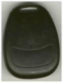
Click to zoom
Application Details
- Equipment Class
- DSC - Part 15 Security/Remote Control Transmitter
- Date of Grant
- Aug 10, 1999
- Application Purpose
- Original Equipment
- Date of Application
- May 03, 1999
- Equipment Note
- Keyless Entry Transmitter
- Frequency Range
- 418.00000000 - 418.00000000
- Country
- United States
Documents & Files
Document Text
Text extracted from the exhibit documents filed with the FCC. Open a document above to read the original.
Cover Letter(s)
Page 1 of 1 FCC ID: OJS990001 & OJS990002 Letter of Authorization
External Photos
Page 1 of 1 FCC ID: OJS990002 External Photographs of EUT External Front External Back
Internal Photos
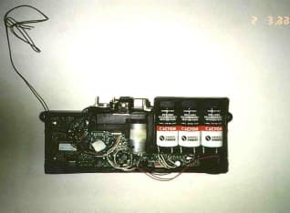
Page 1 of 1 FCC ID: OJS990002 Internal Photographs of EUT Internal Front Internal Back PCB Component front PCB Component without battery PCB Foil
Operational Description
Page 1 of 1 FCC ID: OJS990001 & OJS990002 Product Description Keyless Entry System Using Radio Frequency Transmit and Receiver Electronics MET has developed a keyless entry system using a radio frequency transmitter and receiver. The transmitter will transmit a 418 MHz OOK On-Off keying) signal to the receiver. The signal transmitted a digital encrypted using a Keeloq TM rolling code algorithm at a 400 microsecond per bit baud rate, 61 bits per code. The receiver will receive the 418 MHz signal and decode the digital signal using the same Keeloq algorithm. The 3 possible signals that will be decoded by the receiver are unlock, lock, and enable/disable alarm. The microcomputer electronics at the receiver will proceed to perform the requested access control functions. The expected distance from the transmitter to the receiver is a 30-foot range.
Schematics
Page 1 of 1 FCC ID: OJS990002 Schematic Diagrams of EUT
Test Report
315 MHz Transmitter Radiometrics Midwest Corporation Test Document RP-3997A Issue Date: May 7, 1999 This report concerns: Original grant Equipment type: Periodic Transmitter Transition Rules per 15.37 are not requested. Tests Performed ForTest Facility Micro Enhanced Technology, Inc. 100 W. Plainfield Rd., Suite 202 Countryside, IL 60525 Radiometrics Midwest Corporation 12 East Devonwood Romeoville, IL 60446 Phone: (815) 293-0772 FAX: (815) 293-0820 [email protected] Test Report Written ByTest Report Approved By Joseph Strzelecki Senior EMC Engineer NARTE EMC-000877-NE Chris W. Carlson Director of Engineering NARTE EMC-000921-NE MEASUREMENT/TECHNICAL REPORT Micro Enhanced Technology, Inc. Model 990002 FCC ID: OJS990002 APPLICATION FOR CERTIFICATION RF Emission Measurements Performed For Determination of Compliance with the US Code of Federal Regulations Title 47, Chapter I, FCC Part 15 Subpart C As Required for Certification for Intentional Radiators Tests Performed ForFCC IDRadiometrics Test DocumentPage Micro Enhanced Technology, Inc OJS990002RP-3997A2 of 10 Table of Contents 1.0 General Information ..................................................................................................................3 1.1 Product Description ...............................................................................................................3 1.2 Related Submittals ................................................................................................................3 1.3 Tested System Details...........................................................................................................3 1.4 Test Methodology ..................................................................................................................3 1.5 Test Facility............................................................................................................................3 1.6 Test Equipment .....................................................................................................................4 2.0 System Test Configuration........................................................................................................4 2.1 Test System and Justification ................................................................................................4 2.2 EUT Test Configuration ............................................................................................................4 2.3 Special Accessories...............................................................................................................4 2.4 Equipment Modifications........................................................................................................4 Figure 2.1 Configuration of Tested System .................................................................................5 3.0 Occupied Bandwidth Data ........................................................................................................6 Figure 3.1 Occupied Bandwidth Plot ...........................................................................................7 4.0 Radiated Emissions Data..........................................................................................................8 4.1 Field Strength Calculation......................................................................................................9 4.2 Peak to Average Calculations................................................................................................9 Figure 4.1 Duty Cycle Plot .........................................................................................................10 Notice: This report must not be reproduced (except in full) without the written approval of Radiometrics Midwest Corporation. Tests Performed ForFCC IDRadiometrics Test DocumentPage Micro Enhanced Technology, Inc OJS990002RP-3997A3 of 10 1.0 General Information 1.1 Product Description The Model 99002 (referred to as the EUT in this report) is a 418 MHz Transmitter. The EUT is manufactured by Micro Enhanced Technology, Inc. The EUT consists of four momentary push button switches, an RF oscillator (418 MHz SAW based), a single 3V lithium coin cell battery, and a custom IC. In normal use nothing occurs until one of the four buttons is pressed. The RF oscillator is a simple ON-OFF Keyed stage. Once the transmission is complete the custom IC goes into a standby mode and remains inactive until the next button is pressed. 1.2 Related Submittals The associated receiver is currently being submitted pursuant to the Certification equipment authorization as FCC ID: OJS990001. 1.3 Tested System Details The identification for the EUT is as follows. Model Number Serial NumberFCC ID Manufacturer & Description Cable Descriptions M/N: 990002 (EUT)OJS990002Micro Enhanced Technology Inc. 418 MHz Transmitter No cables can be connected to the EUT 1.4 Test Methodology The test procedures used are in accordance with the ANSI document C63.4-1992, (July 17, 1992) "Methods of Measurement of Radio Noise Emissions from Low-Voltage Electrical and Electronic Equipment in the Range of 9 kHz to 40 GHz". The specific procedures are described herein. Radiated testing was performed at an antenna to EUT distance of 3 meters. The antenna was raised and lowered from 1 to 4 meters. 1.5 Test Facility The open area test site used to collect the radiated data is located on 8625 Helmar Road in Newark, Illinois. The open field test site has a metal ground screen. Details of the site characteristics are on file with the FCC. Conducted emission measurements and preliminary radiated emission scans were performed in shielded enclosure “B” at Radiometrics' Romeoville, Illinois EMI test lab. These sites have been fully described in a report and accepted by the FCC in a letter dated October 1, 1996 (31040/SIT 1300F2). Tests Performed ForFCC IDRadiometrics Test DocumentPage Micro Enhanced Technology, Inc OJS990002RP-3997A4 of 10 1.6 Test Equipment Rad…
Text truncated - open the document above for the full version.
Contact Information
Applicant
Lawrence C Brownfield(Vice President)
Technical Contact
Radiometrics Midwest CorporationJoseph R Strzelecki
[email protected]815-293-0772
12 East Devonwood Av. · Romeoville, Illinois · United States
Non-Technical Contact
Radiometrics Midwest CorporationJoan E Strzelecki
[email protected]815-293-0772
Technical Specifications
| # | Rule Parts | Frequency Range | Power Output |
|---|---|---|---|
| 1 | 15C | 418 MHz - 418 MHz | - |
Other Applications from Micro Enhanced Technology, Inc.
OJS990001
Aug 10, 1999Electronic Lock Receiver
Equipment Class
CYY - Communications Receiver used w/Pt 15 Transmitter