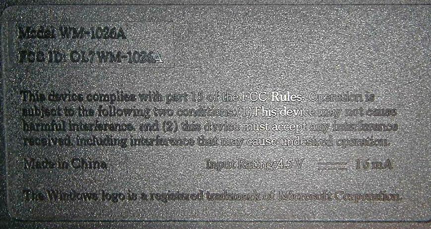
OL7WM-1026AWireless Keyboard
Peracom Networks Inc.
Click to zoom
Application Details
- Equipment Class
- DXX - Part 15 Low Power Communication Device Transmitter
- Date of Grant
- Sep 11, 2000
- Application Purpose
- Original Equipment
- Date of Application
- Sep 11, 2000
- Equipment Note
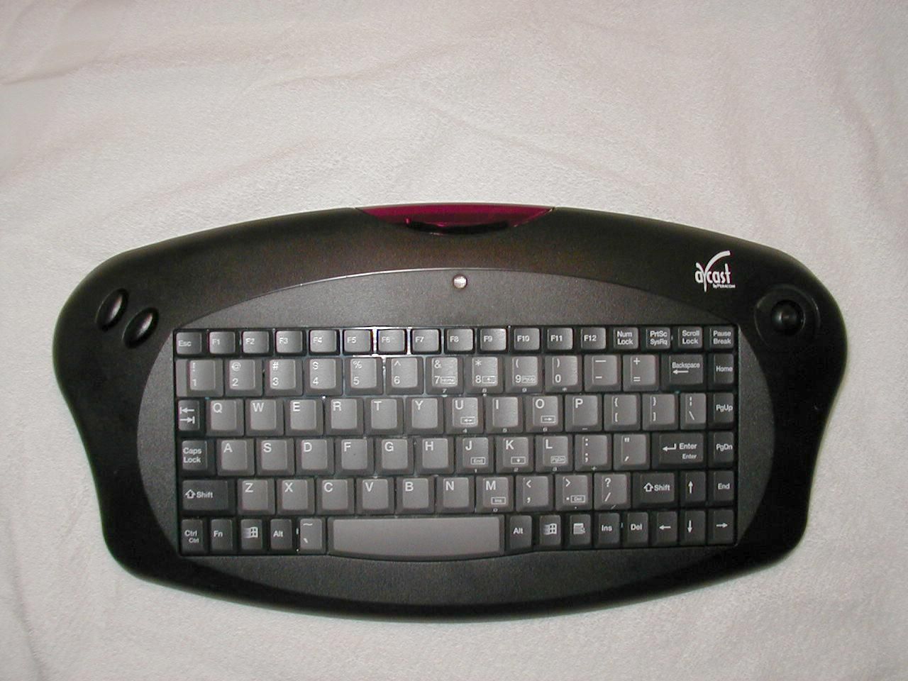
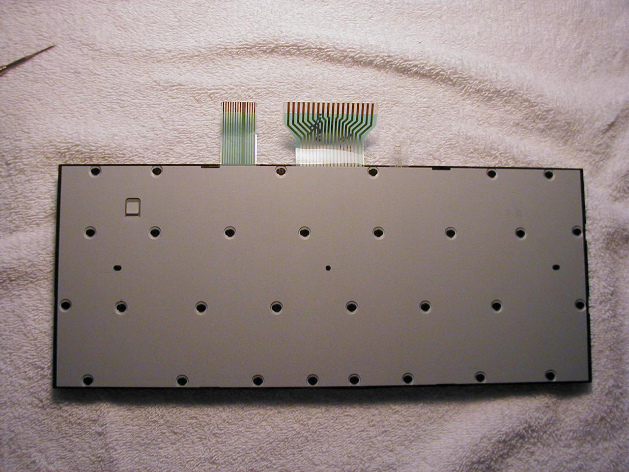
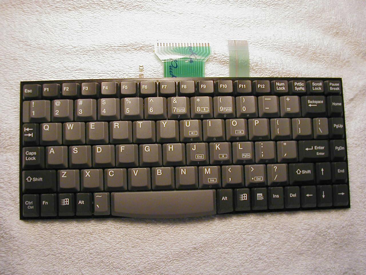
- Wireless Keyboard
- Frequency Range
- 916.50000000 - 916.50000000
- Company
- Peracom Networks Inc.
- Country
- United States
Documents & Files
Document Text
Text extracted from the exhibit documents filed with the FCC. Open a document above to read the original.
Users Manual
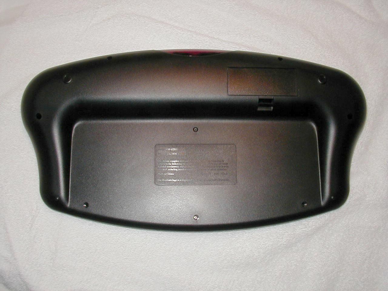
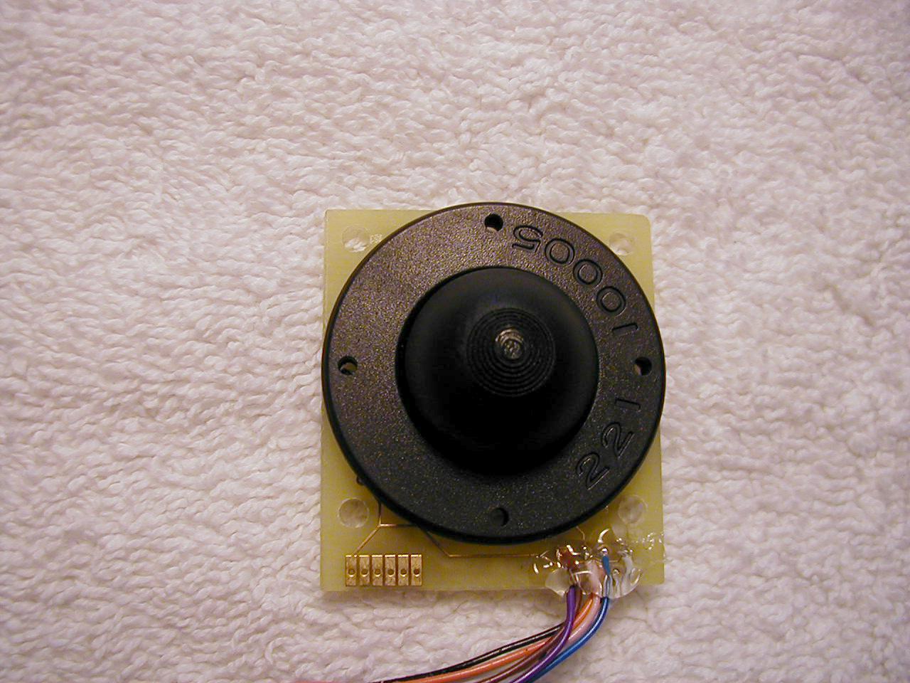
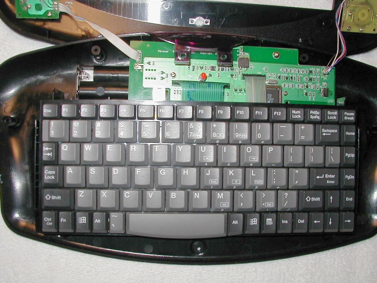
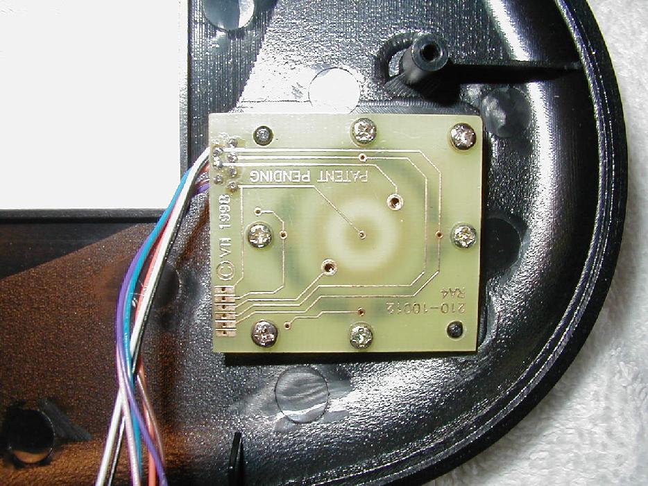
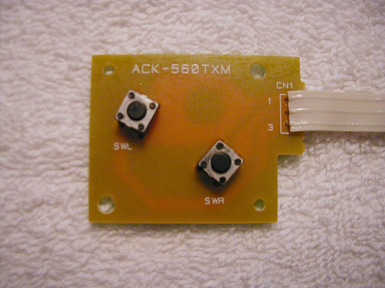
USER’S GUIDE WIRELESS KEYBOARD Important Safety Instructions 1.Read these instructions. 2.Follow all instructions. 3.Keep these instructions. 4.Heed all warnings. 5.Do not use this apparatus near water. 6.Clean only with a damp cloth. 7.Refer all servicing to qualified service personnel. Servicing is required when the apparatus has been damaged in any way, such as the power supply cord or plug is damaged, liquid has been spilled or objects have fallen into the apparatus, the apparatus has been exposed to rain or moisture, or the apparatus does not operate normally or has been dropped. ii FCC Notice NOTICE FEDERAL COMMUNICATIONS COMMISSION This equipment has been tested and found to comply with the limits for a Class B digital device, pursuant to Part 15 of the FCC Rules. Operation is subject to the following two conditions: (1) this device may not cause harmful interference, and (2) this device must accept any interference received, including interference that may cause undesired operation. These limits are designed to provide reasonable protection against harmful interference in a residential installation. This equipment generates, uses, and can radiate radio frequency energy and, if not installed and used in accordance with the instructions, may cause harmful interference to radio communications, However there is no guarantee that interference will not occur in a particular installation. If this equipment does cause harmful interference to radio or television reception, which can be determined by turning the equipment off and on, the user is encouraged to try to correct the interference by one or more of the following measures: •Reorient or relocate the receiving antenna. •Increase the separation between the equipment and receiver. •Connect the equipment into an outlet on a circuit different from that to which the receiver is connected. •Consult the dealer or an experienced radio/TV technician for help. Modifications The FCC requires the user to be notified that any changes or modifications made to this device that are not expressly approved by Peracom Networks, Inc. may void the user's authority to operate the equipment. iii Table of Contents Important Safety Instructions . . . . . . . . . . . . . . . . . . . . . . . . . . . . . . . .ii FCC Notice . . . . . . . . . . . . . . . . . . . . . . . . . . . . . . . . . . . . . . . . . . . . . . iii The Avcast Home Entertainment System . . . . . . . . . . . . . . . . . . . . . .1 Introducing the Wireless Keyboard . . . . . . . . . . . . . . . . . . . . . . . . . . .2 Appendix A: Changing the RF Address. . . . . . . . . . . . . . . . . . . . . . . .7 Appendix B: Wireless Keyboard Specifications . . . . . . . . . . . . . . . . .9 Appendix C: Support and Troubleshooting. . . . . . . . . . . . . . . . . . . .10 Appendix D: Accessories and Replacement Parts. . . . . . . . . . . . . .11 Index . . . . . . . . . . . . . . . . . . . . . . . . . . . . . . . . . . . . . . . . . . . . . . . . . . .13 iv The Avcast Home Entertainment System The Avcast system uses the existing coaxial cable wiring in a house to create a home entertainment network. The Avcast home entertainment network connects television sets (TVs) and a personal computer (PC) together — allowing the user to their PC screen on any television connected to the network. The following is an example of a basic Avcast home entertainment network: personal computer TV OUT card (not included) required for audio/video connection CableCaster PC Caster TV TV wireless mouse filter audio/video cable ground block USB cable wall adapter wireless keyboard TV from cable company or local TV antenna TV wall adapter IRCaster (optional) 1 2 Introducing the Wireless Keyboard The Avcast Wireless Keyboard is used in conjunction with a PC Caster and a PC in the Avcast home entertainment network. The PC Caster allows you to view your personal computer screen on any TV connected to the Avcast network. The keyboard uses radio frequency (RF) to communicate with the PC via the PC Caster, giving you control of the PC from any room in the house. The Wireless Keyboard with a built-in mouse remotely performs all the same functions of a standard keyboard and mouse that are connected to your PC. The Wireless Keyboard is an 88-key Windows keyboard with a built-in mouse that consists of a mouse joystick and a pair of left/right mouse buttons. The keyboard functions similarly to a full-sized keyboard; however there are some physical differences (see the “Using Wireless Keyboard Functions” section for more information). For example, the Num Lock, Caps Lock and Scroll Lock keys have no LEDs to indicate whether they are active or inactive. Also, the Wireless Keyboard does not have a 17-key numeric keypad on the keyboard. Instead, a section of the keys in the main keypad become “extender” keys to perform the numeric keypad functions when the special Function (FN) key is pressed to activate them. The Wireless Keyboard is powered by 3 AA batteries installed in the battery compartment on the back of the keyboard (see Appendix A for Wireless Keyboard Specifications). Other Items in the Kit •AA Batteries (3) •Warranty Card Technical Information The appendixes in the back of this guide provide technical specifications. The Avcast Home Entertainment System How to Use the Wireless Keyboard left/right mouse buttons red LED mouse joystick A B C A B C 3 How to Use the Wireless Keyboard Before you start: •The original PC keyboard and mouse need to be connected to the PC for it to boot up properly. •The PC mouse and keyboard should not be used at the exact same time as the Remote Mouse and Keyboard. Both are attached to the system and function using the same application and using them simultaneously will produce unexpected results. Set Up the Wireless Keyboard 1.Remove the battery compartment cover and insert 3 new AA Batteries (supplied). The Wireless Keyboard is powered by 3 AA batteries located in the battery compartment under a snap-on cover…
Text truncated - open the document above for the full version.
Block Diagram
WM-1026A Block Diagram Bat ter ies 3 AA Flash based Microprocessor 4MHz Crystal Mous e B utto ns Mouse Joystick Mouse Motio n Detec t Circuitry Wake Up Circuitry 916.5 MHz RF Tra ns mitte r Antenna Keypad Ma trix
Operational Description
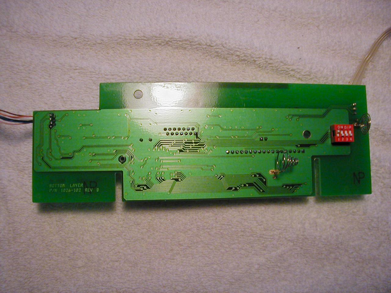
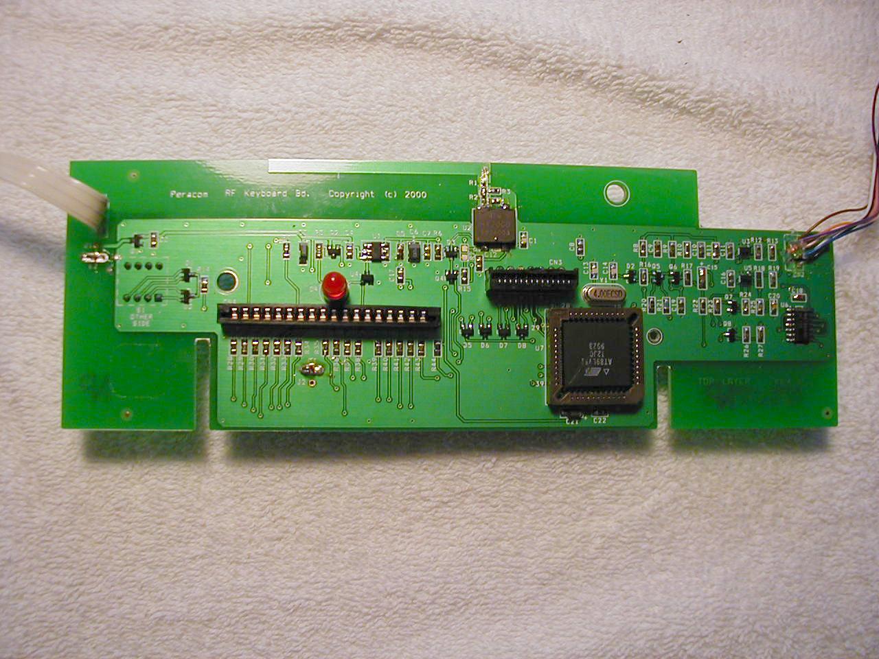
Keyboard Functional Description This product is a low-powered transmitter operating at 916.5 MHz (+/- 200 kHz) containing an antenna integrated into the board design (thus preventing removal and replacement). The EUT contains a voltage regulator, RF Source, and pulse timing circuit in addition to the antenna. Output pulses are produced that represent characters (format described in the test report). A keypad and other small buttons and a joystick-type device on the product provide user input to the keyboard. Power is provided by three 1.5 V “AA” batteries. A separate receive circuit connected to a Personal Computer or similar device decodes the signal for the user.
Schematics
RF Keyboard B Friday, June 16, 2000 Title SizeDocument Number Date: VCC VCC VCC VCC VCC VCC VCC VCC VCC VCC VCC VCC JOYSTICK_SENSE2 NORTH_EAST_DRIVE2 NORTH_SOUTH_ENA EAST_WEST_ENA SOUTH_WEST_DRIVE2 RF_TX_DATA 2 PUSH_B_SENSE2 COL05 COL11 COL10 COL15 COL04 COL06 COL09 COL03 COL02 COL01 COL00 COL13 COL12 COL08 COL07 ROW4 ROW5 ROW7 ROW6 ROW3 ROW4 ROW1 ROW0 COL14 ROW2 COMP-OUT ROW5 LOW_BAT R16 150K R8 56K Y1 4 MHz R20 0 Q5 FMMT4403 Q6 FMMT4403 R22 1K R18 DNP R17 1K R9 1M C15 .22uF D2 BAS16 R321.5K R331.5K R341.5K R351.5K R381.5K R431.5K R371.5K R281.5K R291.5K R361.5K R421.5K R411.5K R301.5K R311.5K R391.5K R401.5K R14 1K R25 510K R44 1K CN1 1 2 3 R15 10K D4 LED RED C8 .01uF C16 .01uF CN3 1 2 3 4 5 6 7 8 9 10 11 12 13 14 + C21 4.7uF 16V C9 0.1uF C14 22pF C13 22pF C22 .01uF C20 1000pF U5 LMC7225IM5 3 4 5 1 2 R19 1M C19 .01uF D8 BAW56 1 23 D7 BAW56 1 23 D6 BAW56 1 23 D5 BAW56 1 23 R21 91K S1 SW DIP-4 1 2 3 4 8 7 6 5 D3 BAV70 12 3 D1 BAV70 12 3 R4 1K C11 .01uF R13 100K R10 51K C10 .01uF R11 51K Q7 FMMT3904 R24 510 U7 AT89LV51-12JC/PLCC44 35 21 20 10 14 15 16 17 2 3 4 5 6 7 8 9 43 42 41 40 39 38 37 36 24 25 26 27 28 29 30 3119 18 32 33 13 11 44 22 EA/VP X1 X2 RESET P3.2 P3.3 P3.4 P3.5 P1.0 P1.1 P1.2 P1.3 P1.4 P1.5 P1.6 P1.7 P0.0 P0.1 P0.2 P0.3 P0.4 P0.5 P0.6 P0.7 P2.0 P2.1 P2.2 P2.3 P2.4 P2.5 P2.6 P2.7P3.7 P3.6 PSEN ALE/P P3.1 P3.0 VCC VSS R23 5.1K R5 150 R12 1M Q2 FMMT4403 U3 LMC7225IM5 4 3 5 1 2 CN4 1 2 3 4 5 6 7 8 9 10 11 12 13 14 15 16 17 18 U4 XC61CN3302M 1 2 3 Vout Vss Vin E E B B C C + Peracom PERACOM CONFIDENTIAL SCH-1026-E.DSN 1026-101 RF Keyboard B 2Friday, June 16, 2000 Title SizeDocument Number Date:Sheet VCC VCC VCC NORTH_SOUTH_ENA1 EAST_WEST_ENA1 NORTH_EAST_DRIVE1 SOUTH_WEST_DRIVE1 JOYSTICK_SENSE1 PUSH_B_SENSE1 RF_TX_DATA1 SOUTH NORTH CTR-SW CTR-SW WEST EAST JOYSTICK_SENSE BAT-PLUS + U2 HX2000 1 2 4 3 C1 100pF C4 0.1uF C5 0.1uF R7 100K DNP +C6 10uF 16V U1 XC62GR3312PR 52 43 OUTIN GNDSW Q3 MGSF1P02LT1 D G S Q8 FMMT3904 R27 4.7K U6B 74HC125 56 4 U6A 74HC125 23 1 R26 100K U6C 74HC125 98 10 C18 0.1uF Q4 ZVN3310F D G S J2 Battery - BLACK 1 J1 Battery + RED 1 Q1 MGSF1P02LT1 D G S + C3 4.7uF 16V C2 .01uF C17 .01uF C12 .01uF E1 R6 1K C7 .01uF R2 39 L1 82nH U6D 74HC125 1211 13 CN2 CON7 DNP 1 2 3 4 5 6 7 R1 39 R3 15 E2 SLOT E3 SLOT Peracom 13000 Weston Parkway Cary, N.C. 27513 U.S.A. PERACOM CONFIDENTIAL 916.5MHZ +3.3V +3.3V MOUSE CONTROL MAIN POWER SUPPLY RF SECTION RF POWER SUPPLY +3.3V 1026-101 RF Keyboard B 3Friday, June 16, 2000 Title SizeDocument Number Date:Sheet of RevDescription FID1 FIDUTIAL FID2 FIDUTIAL FID3 FIDUTIAL TH3 HOLE TH2 HOLE V63V9V8V47V21V28V29V30 TH1 HOLE V31V35V36V14V22V23V25V44V54V34V1 V16V24V52V19V48V10V39V45V50V38V18V15V13V33V46 V26V20V2V3V4V5V6V7V43V11 V59V49V58V41 V51V42V60V61V57V12V53V56V62 V27 V32 V37 V17 V40 V55 A3PC Board, RF Keyboard1026-102-E1 A2Schematic, RF Keyboard1026-101-EDNP A1Bill of Material, RF Keyboard1026-100-EDNP Peracom 13000 Weston Parkway Cary, N.C. 27513 U.S.A. PERACOM CONFIDENTIAL ANC C BAS16 SOT23 Top View BE C FMMT4403 S0T23 Top View GS D ZVN3310F S0T23 Top View 123 XC62GR3312PR S0T-89-5 Top View GS D MGSF1P02LT1 S0T23 Top View 45 FMMT3904 S0T23 Top View C BE123 LMC7225IM5 S0T-23-5 Top View 45 BAV70 S0T23 Top View 1 32 BAW56 S0T23 Top View 1 32 VoutVss Vin XC61CN3302M S0T23 Top View DesigQTYPeracom P/NDescription D Changed keypad connections: Pin 4 to COL13 and Pin 5 to COL14 Changed NE and SW to U7-3.6 & U7-3.7 Moved mouse Button Com to U7-0.1 Added battery terminal pads E2 & E3 E Added Thermal Relief to E3
Test Report
Project: 00RT8098 File: MC1072 Report: 000236 Date: June 19, 2000 Model: WM1026A FCC ID: OL7WM-1026A Test Report On Electromagnetic Compatibility Testing Peracom, Inc. Cary, NC USA Copyright 2000 Underwriters Laboratories Inc. Underwriters Laboratories Inc. authorizes the above-named company to reproduce this Report provided it is reproduced in its entirety. Project: 00RT8098Underwriters Laboratories, Inc.Issued: 06/19/00 File: MC1072Test Report on Electromagnetic CompatibilityPage 2 of 49 FCC ID: OL7WM-1026ATest Report: 000236 Test Report Details: Tests Performed By: Underwriters Laboratories Inc. 12 Laboratory Drive Research Triangle Park, NC 27709 Tests Performed For: Peracom, Inc. 13000 Weston Parkway Suite 105 Cary, NC 27513 USA Applicant Contact: Mr. Ralph Yeager Engineer Voice: (919) 379-2763 Test Report Number: 000236 Test Report Date: June 19, 2000 (Revised August 11, 2000) Product Type: Wireless Keyboard Model Number: WM1026A Sample Serial Number: Pre-production manufactured sample Sample Tag Number: S00LB275B EUT Category: Transmitter EUT Type: Table Top Sample Receive Date: June 14, 2000 Testing Start Date: June 14, 2000 Date Testing Complete: June 17, 2000 Underwriters Laboratories Inc. reports apply only to the specific samples tested under stated test conditions. All samples tested were in good operating condition throughout the entire test program. It is the manufacturer's responsibility to assure that additional production units of this model are manufactured with identical electrical and mechanical components. Underwriters Laboratories Inc. shall have no liability for any deductions, inferences or generalizations drawn by the client or others from Underwriters Laboratories Inc. issued reports. This report shall not be used to claim, constitute or imply product certification, approval, or endorsement by NVLAP or any agency of the US government. This report may contain data which is not covered by the NVLAP accreditation. Only data which is noted under Remarks of Summary of Testing as being NVLAP Accredited Data can be considered to be covered by the NVLAP accreditation. Project: 00RT8098Underwriters Laboratories, Inc.Issued: 06/19/00 File: MC1072Test Report on Electromagnetic CompatibilityPage 3 of 49 FCC ID: OL7WM-1026ATest Report: 000236 Summary of Testing: TestTest NameComplyDoes NotSee #Test Requirement/SpecificationComplyRemark 1Radiated Disturbance Emissions - 9 kHz to 30 MHzX-1 47 CFR Part 15, Subpart C / 47 CFR Part 15, Subpart C Section 15.209 2Radiated Disturbance Emissions - 30 to 1000 MHz Electric FieldX-1 47 CFR Part 15, Subpart C / 47 CFR Part 15, Subpart C Sections 15.209 and 15.249 3Radiated Disturbance Emissions - 1 to 10 GHz Electric FieldX-1 47 CFR Part 15, Subpart C / 47 CFR Part 15, Subpart C Sections 15.209 and 15.249 4Radiated Disturbance Emissions - Occupied BandwidthX-1 47 CFR Part 15, Subpart C / 47 CFR Part 15, Subpart C Section 15.249 5Radiated Disturbance Emissions - Peak-to-Average RatioN/AN/A2 47 CFR Part 15, Subpart C / 47 CFR Part 15, Subpart C Section 15.249 6Radiated Disturbance Emissions - Restricted Bands of OperationX- 47 CFR Part 15, Subpart C / 47 CFR Part 15, Subpart C Section 15.205 Remarks: 1)The EUT was found to comply with FCC Part 15 Section 15.249 rules for transmitters in 902-928 MHz band. For spurious emissions the EUT was found to comply with the general rules for low-powered transmitters in Section 15.209 and Restricted Bands in Section 15.205. Results can also be considered applicable to Canadian RSS-210 Issue 2, Rev.1 Section 6.2.2. 2)No limit applies. Result used to calculate average value from peak measurement for Tests 1 through 4. 3)Emissions Designator interpreted to be P0D341K per FCC Part 2.201. Conclusion: The tests listed in the Summary of Testing section of this report have been performed and the results recorded by Underwriters Laboratories Inc. in accordance with the procedures stated in each test requirement and specification. The test list was determined by the Applicant as being applicable to the Equipment Under Test. As a result, the subject product has been verified to comply or not comply as noted in the Summary of Testing with each test specification. The test results relate only to the items tested. Project: 00RT8098Underwriters Laboratories, Inc.Issued: 06/19/00 File: MC1072Test Report on Electromagnetic CompatibilityPage 4 of 49 FCC ID: OL7WM-1026ATest Report: 000236 Test Facilities: Test Location A) 10-Meter Anechoic Chamber (Industry Canada - IC 2953, NVLAP - 200246-0, VCCI - R-722) Constructed by Lindgren RF Enclosures, this room consists of a 17.9 by 12 by 8.3 m (inside clearance) shielded room lined with TDK absorber material. The walls, floor (conducting ground plane) and ceiling are constructed of double sided galvanized sheet steel supported by 19 mm thick particle board. The interior walls and ceiling are covered with 10 by 10 cm, 4.6 mm thick ferrite tiles and partially covered with polystyrene absorber cones. Removable floor tiles and cones covering the floor between the EUT and antenna are provided when RF immunity testing is performed. Room is provided with a 4.0 m diameter embedded turntable and a 1.2 by 2.1 m and 2.4 by 2.4 m double knife edge doors for access. Also, the room is fed electrical EUT power via permanently installed filters and is provided with a permanently mounted video surveillance camera. A remotely controllable antenna mast is located in the room for positioning the measuring antenna from 1 to 4 m above the ground plane. Test Location B) Compact Anechoic Chamber Constructed by Lindgren RF Enclosures, this room consists of a 6 by 3 by 2.9 m (inside clearance) shielded room lined with TDK absorber material. The walls, floor (conducting ground plane) and ceiling are constructed of double sided galvanized sheet steel supported by 19 mm thick particle board. The interior walls and ceiling are covered with 10 by 10 cm, 4.6 mm thick ferrite tiles and partially covered w…
Text truncated - open the document above for the full version.
Test Setup Photos
Project: 00RT8098Underwriters Laboratories, Inc.Issued: 06/19/00 File: MC1072Test Report on Electromagnetic CompatibilityPage 17 of 49 FCC ID: OL7WM-1026ATest Report: 000236 Test 1, Item A - Test Set-Up Photo:Radiated Disturbance Emissions - 9 kHz to 30 MHz Electric Field (Test Set-Up photo representative of all test performed)
Contact Information
Applicant
Ralph Yeager(Senior Engineer)
Technical Contact
PeracomRalph C Yeager
[email protected](919) 379-2763
5150 McCrimmon Parkway Suite 401 · Morrisville, North Carolina · United States
Non-Technical Contact
PeracomRalph C Yeager
[email protected](919) 379-2763
Test Firm
UL LLCRick Titus
Technical Specifications
| # | Rule Parts | Frequency Range | Power Output | Tolerance |
|---|---|---|---|---|
| 1 | 15C | 916.5 MHz - 916.5 MHz | - | 218.0000000000 ppm |
Other Applications from Peracom Networks Inc.

OL7WM-1025A
Sep 10, 2000Wireless Mouse
Equipment Class
DXX - Part 15 Low Power Communication Device Transmitter