OLPSLHUBRF900MZWireless communication hub
Telsco Industries, Inc.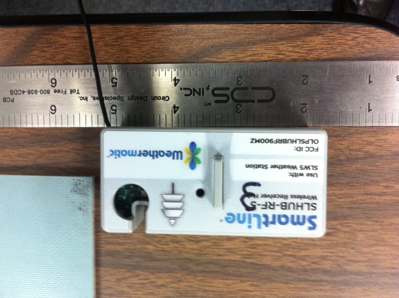
Click to zoom
Application Details
- Equipment Class
- DSS - Part 15 Spread Spectrum Transmitter
- Date of Grant
- Mar 31, 2014
- Application Purpose
- Original Equipment
- Date of Application
- Mar 31, 2014
- Equipment Note
- Wireless communication hub
- Frequency Range
- 902.35000000 - 927.60000000
- Company
- Telsco Industries, Inc.
- Country
- United States
Documents & Files
Document Text
Text extracted from the exhibit documents filed with the FCC. Open a document above to read the original.
Users Manual
The RFS5 is a wireless rain/freeze sensor operating on a 900 MHz bi-directional frequency. Maximum range is 1500 feet (457m) Line of Sight (LOS). The RFS5 is operable with all ProLine® models and firmware versions. The RFS and RFSHUB-5 are “pre-paired” or synced at the factory for your convenience. 1. Install the RFSHUB-5. The RFSHUB-5 is the wireless transceiver that communicates with the RFS5. The RFSHUB-5 is supplied with your RFS5. To install in your ProLine® controller, open the control panel/door on the 1600/4800 models. On the 800 model, remove and discard the “hub cover panel” from the back of the housing. Insert the RFSHUB-5 into the mating pin connector holes. Be careful not to bend the connecting pins. Secure the RFSHUB-5 to the housing with the supplied flathead machine screw. The RF antenna will hang down inside the 1600 or 4800 model’s housing. On the 800 model, allow the RF antenna to hang underneath the controller. Make sure AC power is supplied to the ProLine® controller and then proceed to Step No. 2. 2. Initializing RFS5 rain/freeze sensor a. While standing in front of the controller, press the rain switch on the top of the RFS5 for 15 seconds; then watch the LED (which can be seen by openings the cover at the bottom of the RFS5). You will see 4 blinks. All blinks should be Green. The 4th (final blink) indicates the strength of the RF communication. If the 4th blink is Red, you do not have a satisfactory RF communication. Move the RFS5 to a different mounting location and repeat the diagnostic procedure. Note: The 1st LED blink indicates the strength of the 2 AAA lithium batteries in the RFS5. A Red blink would indicate a need to replace the batteries. Capable life for the lithium batteries is around 10 years. If the 2nd and 3rd blinks are Red, complete replacement of the rain/freeze sensor is required. Note: A separate RFS5 rain/freeze sensor is required for each ProLine® controller that you are installing. Determine communication range and choose location While still standing at the controller, press the rain sensor wick for 15 seconds. If you have RF communication, the antenna icon on the ProLine® display should be blinking. Note: The blinking will continue for 5 minutes after any communication from the RFS5. After 5 minutes, the antenna icon will remain static until the next communication. Press the blue “Rain/ Freeze Sensor” button, on the right side of the controller panel, so that it is in the “On” position. The LED should be Green. If it is Red, repeat Step 2. In addition, the operating panel on and PL1600 or PL4800 must be closed so that AC is present. You will get a communication error if the panel is showing NO AC. 3. Mounting the RFS5 a. Decide on a good mounting location for your RFS5 wireless rain/freeze sensor. Mounting is preferred in direct sunlight with good airflow. Additionally, the location must have open access to rainfall (cannot be covered by any overhead obstruction such as trees, roofs, etc.). Mount the RFS5 as close as possible to the controller. Obstacles such as earth, hills, walls or other structures will reduce the maximum operating range of the RFS5. Refer to the LED inside the bottom of the RFS5 to verify communication and to check operating range at a specific location. Extreme conditions may prevent wireless communication. b. Attach mounting bracket to a smooth surface using the two mounting screws (supplied) or attach to gutter using the wing nut provided. You may choose to remove the mounting bracket from the bracket arm for easier installation. Make sure the RFS5 is fixed in a vertical position. Tighten all wing nuts to make sure unit is held vertical. RFS5 Rain/Freeze Sensor Installation Instructions www.weathermatic.com TEST AC1 SENSEN COM P/MV Installed and connected RFSHUB-5 Communication Hub inch 1/2 3/4 1/4 1/8 Attach bracket to gutter. Attach sensor in vertical position. Rain/Free ze Sensing Function The RFS5 wireless r ain/fr ee ze sensor provides rain and freeze sensing functions to prevent watering during periods of rain and free zing wea ther. T he rain override will pause watering after a minimum of 1/4 inch (6.35mm) of rainfall is rec eived, based on the 1/ 4 inch (6.35mm) factory rain sensor setting. Settings can be changed incrementally up to 3/4 inch (19mm). The RFS5 freeze sensing function will prevent watering when the outside temperature dr ops below 37 degrees Fahrenheit (1.5 degrees Celsius) and allow watering to resume when the temperature increases above 37 degrees F (1.5 degrees Celsius). The Sensor LED will display RED during rain or free ze periods. Additionally, after a rain event, the ProLine® controller will continue to pause watering for 48 hours after the rain sensor has disengaged in or der to prevent over watering. During the 48-hour ext ended rain delay, the sensor LED is ORANGE. In the event you choose to end the 48-hour ext ended rain delay, pres s the Rain/ Fr ee ze Sensor button twice and the sensor LED will return to a GREEN color and permit watering. The ProLine® controller has an SLW DLY function (under Advanced Fea tures on the dial), you can adjust the factory default setting of 48 hours delay to a period of 0–99 hours. Troubleshooting and Maintenance The RFS5 sensor and the RFSHUB-5 hub have a factory installed security code that will enable communication only between those two units. Theref or e if you ever need replace an RFS5 always install the mating RFSHUB-5 that ships with the unit. Aft er replacing both components, you should reactivate the RFS5 using step 2 above to assure communication. The RFS5 wireless r ain/fr ee ze sensor is designed for years of maintenance free operation. You will need to change the two AAA lithium batt eries after approximately 10 years of operation. Changing Lithium Batt eries To change the RFS5 wireless r ain/fr eeze sensor batt eries. • Loosen the bottom cover screws on the RFS5 and rotate the cover in the keyholes and remove the cover . • Replace the e…
Text truncated - open the document above for the full version.
Operational Description
OPERATIONAL DESCRIPTION The SLW5 is a wireless weather station operating on a 900 MHz bi‐directional frequency. Maximum range is 1500 feet (457m) Line of Sight (LOS). The SLW5 is operable with all SmartLine® models and firmware versions. The SLW5 and SLHUB‐RF‐5 are “pre‐paired” or synched at the factory for your convenience. The system hops to channel frequencies that are selected at the system hopping rate from a pseudo randomly ordered list of hopping frequencies. Each frequency is used equally on the average by each transmitter. The receivers have input bandwidths that match the hopping channel bandwidths of their corresponding transmitters and shift frequencies in synchronization with the transmitted signals. The transmitter normally transmits all information in one hop. The system is designed to stay in sequence so subsequent transmissions will be on the next hopping channel and does not reset to the initial channel. If forced into continuous transmission the transmitter conforms to all requirements and uses all channels equally. The hopping sequence was generated randomly. Here is the channel sequence for the 50 channels used: 14, 4,19,41,25,35,38, 6,11, 1, 23,26,45,47, 5,17,39,10,15,28, 9,30, 7,44,34,20,22,21, 8, 0, 32,16,43,42,36,49,29,18,46,40, 31,48,37, 2,13,33,27,12,24, 3 The system does not use any type of coordination system.
RF Exposure Info
Prediction of MPE limit at a given distance Equation from page 18 of OET Bulletin 65, Edition 97-01 where:S = power density P = power input to the antenna G = power gain of the antenna in the direction of interest relative to an isotropic radiator R = distance to the center of radiation of the antenna Maximum peak output power at antenna input terminal:14.6(dBm)* Maximum peak output power at antenna input terminal:28.8(mW) Antenna gain(maximum):0 (dBi)* Maximum antenna gain:1.00(numeric) Time Averaging:100 (%)* Prediction distance:20(cm)* Prediction frequency:902(MHz)* MPE limit for uncontrolled exposure at prediction frequency:0.601(mW/cm^2) Power density at prediction frequency:0.0057(mW/cm^2) This equates to:0.0574W/m^2 2 4R PG S π =
Test Report
Nemko Test Report: 10233152RUS2 Applicant: Weathermatic 3301 Kingsley Road Garland, TX 75041 USA Equipment Under Test: SLHUBRF-5 (E.U.T.) FCC ID# OLPSLHUBRF900MZ In Accordance With: FCC Part 15, Subpart C, 15.247 Frequency Hopping Transmitters Tested By: Nemko USA Inc. 802 N. Kealy Lewisville, Texas 75057-3136 TESTED BY: DATE: 16 November 2012 David Light, Senior Wireless Engineer APPROVED BY: DATE: 29 April 2013 Michael Cantwell, Reviewer Total Number of Pages: 38 Nemko USA, Inc. FCC PART 15, SUBPART C FREQUENCY HOPPING SPREAD SPECTRUM TRANSMITTER EQUIPMENT: SLHUBRF-5 PROJECT NO.:10233152RUS2 Table of Contents SECTION 1. SUMMARY OF TEST RESULTS 3 SECTION 2. EQUIPMENT UNDER TEST (E.U.T.) 5 SECTION 3. CHANNEL SEPARATION 7 SECTION 4. TIME OF OCCUPANCY 12 SECTION 5. PEAK POWER OUTPUT 16 SECTION 6. SPURIOUS EMISSIONS (ANTENNA CONDUCTED) 17 SECTION 7. SPURIOUS EMISSIONS (RADIATED) 26 SECTION 8. POWERLINE CONDUCTED EMISSIONS 28 SECTION 9. TEST EQUIPMENT LIST 31 ANNEX A - TEST DETAILS 32 ANNEX B - TEST DIAGRAMS 40 Page 2 of 41 Nemko USA, Inc. FCC PART 15, SUBPART C FREQUENCY HOPPING SPREAD SPECTRUM TRANSMITTER EQUIPMENT: SLHUBRF-5 PROJECT NO.:10233152RUS2 Section 1. Summary of Test Results Manufacturer: Weathermatic Model No.: SLHUBRF-5 Serial No.: None General: All measurements are traceable to national standards. These tests were conducted on a sample of the equipment for the purpose of demonstrating compliance with Part 15, Subpart C, Paragraph 15.247 for Frequency Hopping Spread Spectrum devices. Radiated tests were conducted is accordance with ANSI C63.4-2003. Radiated emissions are made on an open area test site. A description of the test facility is on file with the FCC. New Submission Production Unit Class II Permissive Change Pre-Production Unit THIS TEST REPORT RELATES ONLY TO THE ITEM(S) TESTED. THE FOLLOWING DEVIATIONS FROM, ADDITIONS TO, OR EXCLUSIONS FROM THE TEST SPECIFICATIONS HAVE BEEN MADE. See “ Summary of Test Data”. Nemko USA, Inc. authorizes the above named company to reproduce this report provided it is reproduced in its entirety, for use by the company’s employees only. This report must not be used to claim product certification, approval, or endorsement by NVLAP, NIST, or any agency of the Federal Government. Nemko USA, Inc. is a NVLAP accredited laboratory. Any use which a third party makes of this report, or any reliance on or decisions to be made based on it, are the responsibility of such third parties. Nemko USA, Inc. accepts no responsibility for damages, if any, suffered by any third party as a result of decisions made or actions based on this report. This report applies only to the items tested. Page 3 of 41 Nemko USA, Inc. FCC PART 15, SUBPART C FREQUENCY HOPPING SPREAD SPECTRUM TRANSMITTER EQUIPMENT: SLHUBRF-5 PROJECT NO.:10233152RUS2 Summary Of Test Data NAME OF TEST PARA. NO. RESULT Powerline Conducted Emissions 15.207(a) Complies Channel Separation 15.247(a)(1) Complies Time of Occupancy 15.247(a)(1) Complies 20 dB Occupied Bandwidth 15.247(a)(1) Complies Peak Power Output 15.247(b) Complies Spurious Emissions (Antenna Conducted) 15.247(d) Complies Spurious Emissions (Radiated) 15.247(d) Complies Footnotes: Page 4 of 41 Nemko USA, Inc. FCC PART 15, SUBPART C FREQUENCY HOPPING SPREAD SPECTRUM TRANSMITTER EQUIPMENT: SLHUBRF-5 PROJECT NO.:10233152RUS2 Section 2. Equipment Under Test (E.U.T.) General Equipment Information Frequency Band: 902 – 928 MHz 2400 – 2483.5 MHz 5725 – 5850 MHz Operating Frequency Range: 902.35 to 927.6 MHz Number of Channels: 50 Channel Spacing: 513 kHz Channel Bandwidth: 178 kHz User Frequency Adjustment: Software controlled Input Power: 120 Vac Page 5 of 41 Nemko USA, Inc. FCC PART 15, SUBPART C FREQUENCY HOPPING SPREAD SPECTRUM TRANSMITTER EQUIPMENT: SLHUBRF-5 PROJECT NO.:10233152RUS2 Description of EUT The SLHUB-RF-5 communicates with the SLW5 weather station and sends data to the control panel for lawn irrigation system. System Diagram Page 6 of 41 Nemko USA, Inc. FCC PART 15, SUBPART C FREQUENCY HOPPING SPREAD SPECTRUM TRANSMITTER EQUIPMENT: SLHUBRF-5 PROJECT NO.:10233152RUS2 Section 3. Channel Separation NAME OF TEST: Channel Separation PARA. NO.: 15.247(a)(1) TESTED BY: David Light DATE: 15 November 2012 Test Results: Complies. Measurement Data: See 20 dB BW plot Measured 20 dB bandwidth: 178 kHz Channel Separation: 513 kHz Equipment Used: 1036-1082-1472 Measurement Uncertainty: 1X10 -7 ppm Temperature: 20 °C Relative Humidity: 31 % Page 7 of 41 Nemko USA, Inc. FCC PART 15, SUBPART C FREQUENCY HOPPING SPREAD SPECTRUM TRANSMITTER EQUIPMENT: SLHUBRF-5 PROJECT NO.:10233152RUS2 Test Data – Channel Separation Page 8 of 41 Nemko USA, Inc. FCC PART 15, SUBPART C FREQUENCY HOPPING SPREAD SPECTRUM TRANSMITTER EQUIPMENT: SLHUBRF-5 PROJECT NO.:10233152RUS2 Test Data – 20 dB Bandwidth Low Channel Page 9 of 41 Nemko USA, Inc. FCC PART 15, SUBPART C FREQUENCY HOPPING SPREAD SPECTRUM TRANSMITTER EQUIPMENT: SLHUBRF-5 PROJECT NO.:10233152RUS2 Test Data – 20 dB Bandwidth Mid Channel Page 10 of 41 Nemko USA, Inc. FCC PART 15, SUBPART C FREQUENCY HOPPING SPREAD SPECTRUM TRANSMITTER EQUIPMENT: SLHUBRF-5 PROJECT NO.:10233152RUS2 Test Data – 20 dB Bandwidth High Channel Page 11 of 41 Nemko USA, Inc. FCC PART 15, SUBPART C FREQUENCY HOPPING SPREAD SPECTRUM TRANSMITTER EQUIPMENT: SLHUBRF-5 PROJECT NO.:10233152RUS2 Section 4. Time of Occupancy NAME OF TEST: Time of Occupancy PARA. NO.: 15.247(a)(1) TESTED BY: David Light DATE: 15 November 2012 Test Results: Complies. Measurement Data: See attached plots Maximum Dwell Time On Any Channel: 29.7 ms in 20 seconds Equipment Used: 1036-1082-1472 Measurement Uncertainty: 1X10 -7 ppm Temperature: 20 °C Relative Humidity: 31 % Page 12 of 41 Nemko USA, Inc. FCC PART 15, SUBPART C FREQUENCY HOPPING SPREAD SPECTRUM TRANSMITTER EQUIPMENT: SLHUBRF-5 PROJECT NO.:10233152RUS2 Test Data – Time of Occupancy Pulse Width Page 13 of 41 Nemko USA, Inc. FCC PART 15, SUBPART C FREQUENCY HOPPING SPREAD SPECTRUM TRANSMITTER EQUIP…
Text truncated - open the document above for the full version.
Contact Information
Applicant
Venkataramu Bangalore(Director-Engineering)
Technical Contact
Non-Technical Contact
Nemko CanadaJenny Gibbs
[email protected]940-455-2246
Test Firm
Nemko Canada Inc. (Ottawa)Charles Neal
Technical Specifications
| # | Rule Parts | Frequency Range | Power Output |
|---|---|---|---|
| 1 | 15C | 902.35 MHz - 927.6 MHz | 29.00 mW |
Other Applications from Telsco Industries, Inc.
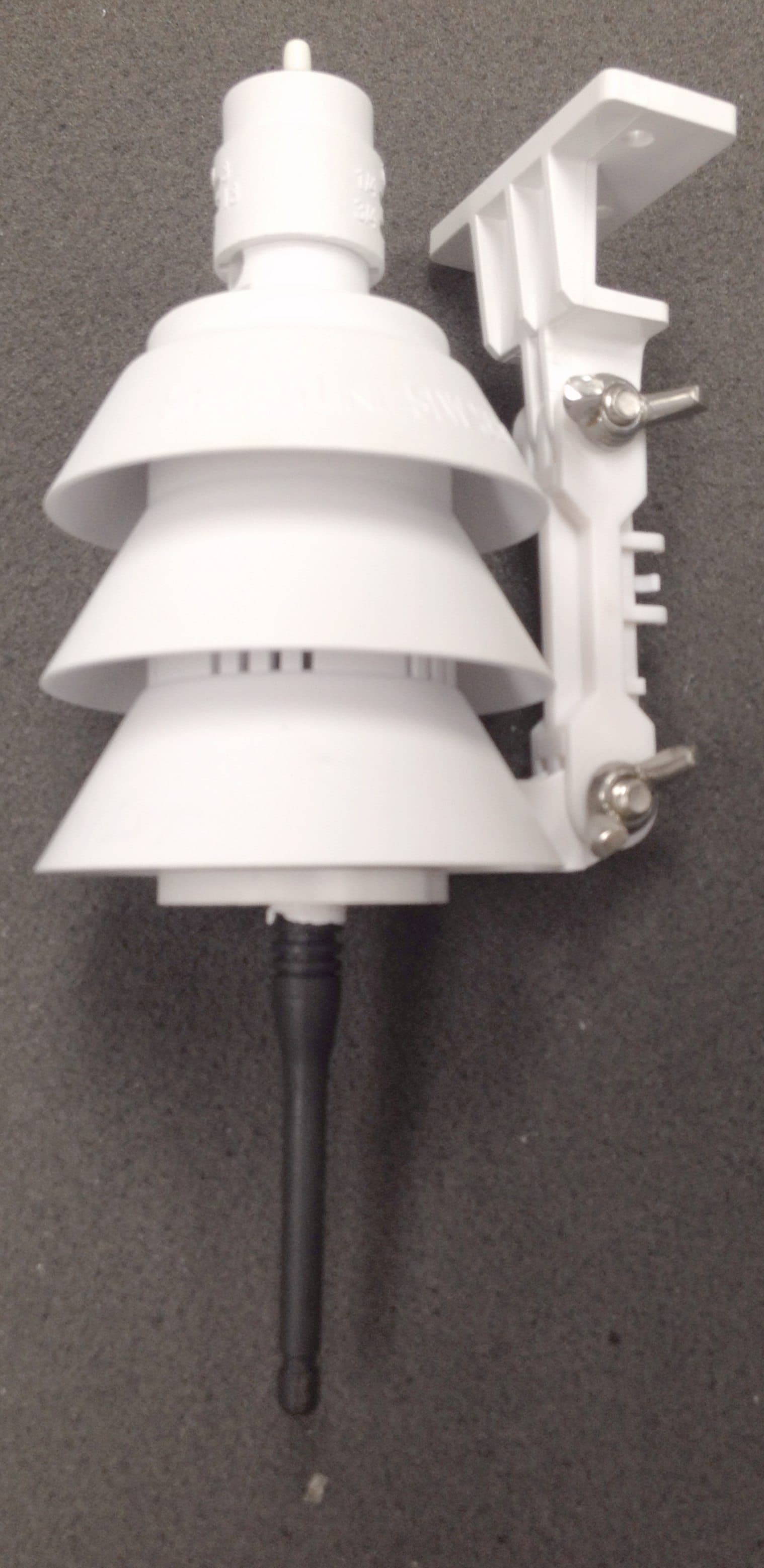
OLPSLW5900MZ
Mar 31, 2014Outdoor weather station
Equipment Class
DSS - Part 15 Spread Spectrum Transmitter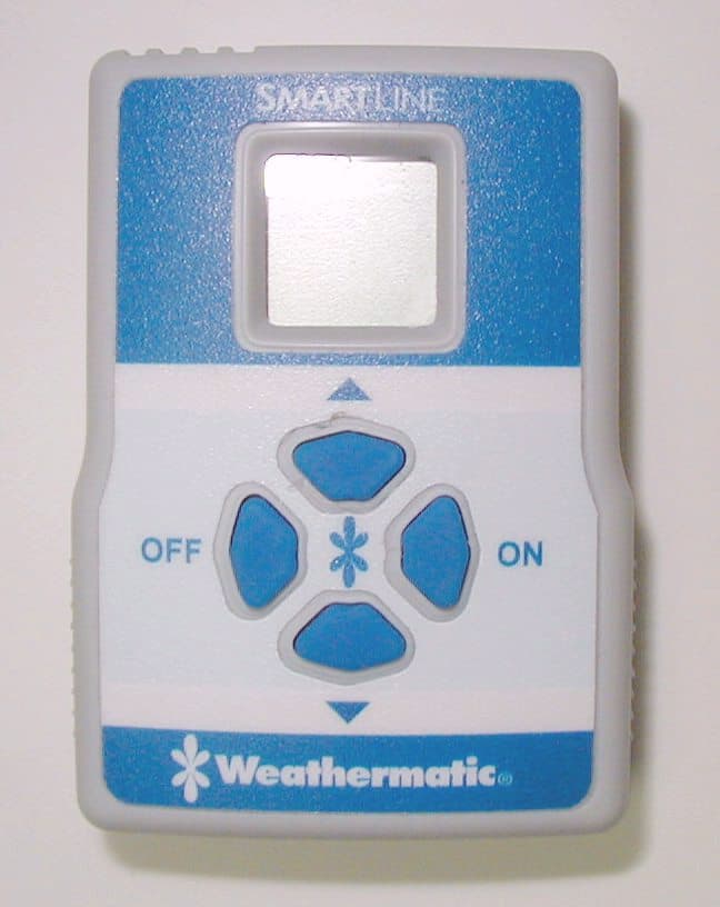
OLPSLHHR24
May 18, 2010SLRC HAND HELD TRANSMITTER
Equipment Class
DXX - Part 15 Low Power Communication Device Transmitter
OLPWM-RR
Oct 25, 1999Irrigation System Receiver
Equipment Class
CYY - Communications Receiver used w/Pt 15 Transmitter
OLPWM-RT
Sep 23, 1999Hand held transmitter used to operate irrigation s
Equipment Class
DXX - Part 15 Low Power Communication Device Transmitter