OM3VTRAKH150VEHICLE TRACKING UNIT
Galaxy Tracking Systems L.L.C.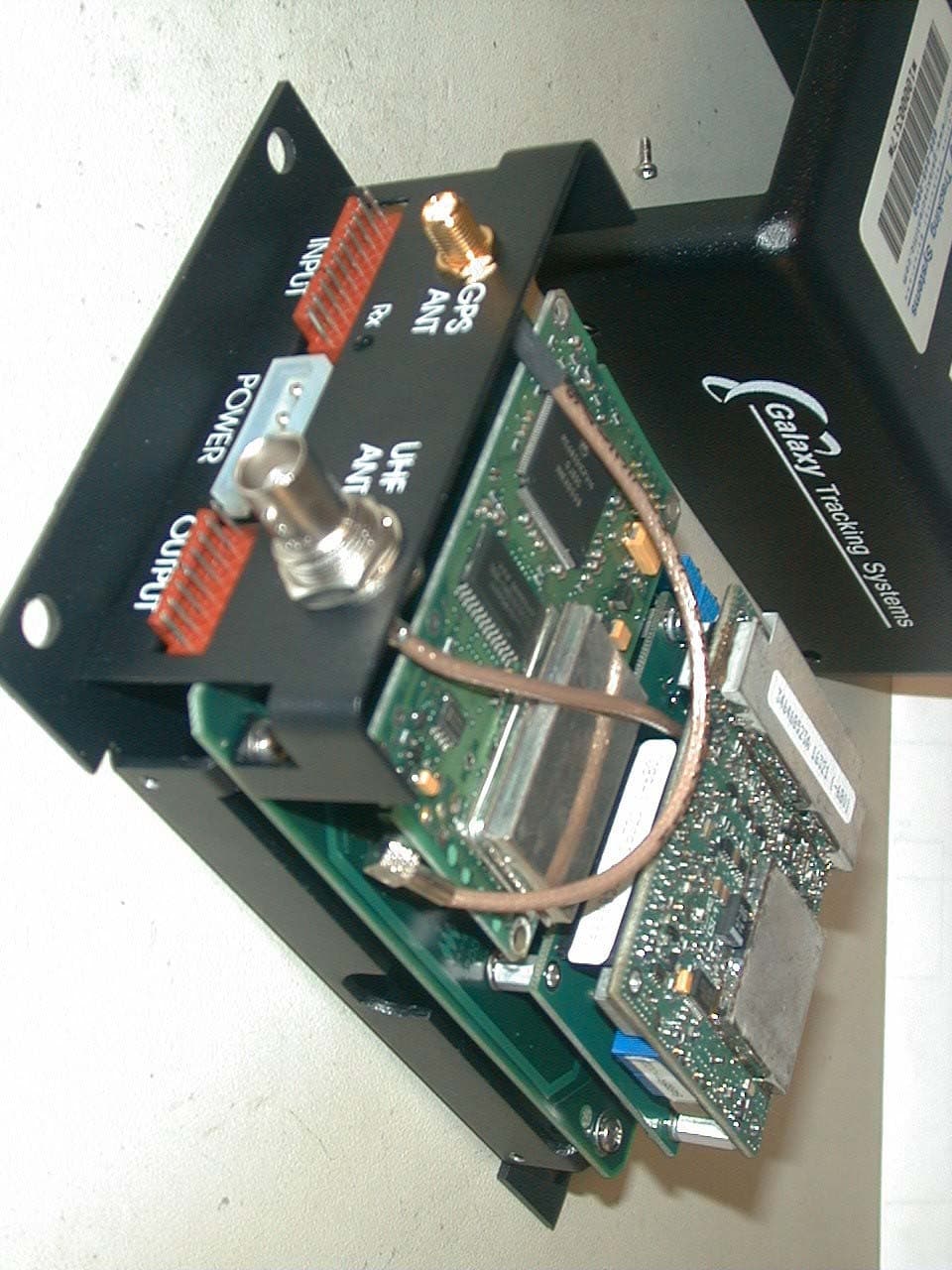
Click to zoom
Application Details
- Equipment Class
- TNB - Licensed Non-Broadcast Station Transmitter
- Date of Grant
- Jun 22, 2004
- Application Purpose
- Original Equipment
- Date of Application
- Jun 22, 2004
- Equipment Note
- VEHICLE TRACKING UNIT
- Frequency Range
- 150.00000000 - 174.00000000
- Country
- United States
Documents & Files
Document Text
Text extracted from the exhibit documents filed with the FCC. Open a document above to read the original.
Users Manual
Vehicle Location and Tracking System (VLaTS) Vehicle Transceiver Unit (VTU) User’s Guide 7 Sept 1999 Prepared By: Galaxy Scientific Corp. 600 Louis Drive Suite 202 Warminster, PA 18974 (215) 672-8005 FAX (215) 672-8708 Table of Contents 1 INTRODUCTION .................................................................................................................................. 6 2 SCOPE ................................................................................................................................................. 6 3 APPLICABLE DOCUMENTS .............................................................................................................. 6 4 SPECIFICATIONS ............................................................................................................................... 6 5 SYSTEM OVERVIEW .......................................................................................................................... 7 5.1 M OBILE COMPONENTS........................................................................................................................ 7 5.2 F IXED COMPONENTS.......................................................................................................................... 8 5.3 RF TRANSMISSION SCHEME............................................................................................................... 8 5.4 SYSTEM TIMING.................................................................................................................................. 8 6 VTU COMPONENTS............................................................................................................................ 9 6.1 VTU S YSTEM ENCLOSURE................................................................................................................. 9 6.1.1 GPS Receiver.......................................................................................................................... 9 6.1.2 Radio ....................................................................................................................................... 9 6.1.3 System Controller .................................................................................................................... 9 6.2 A NTENNAS AND CABLES................................................................................................................... 10 6.3 O PTIONAL COMPONENTS.................................................................................................................. 10 6.3.1 Switch Box (Alarms and Indicators) ...................................................................................... 10 6.3.2 Relay Box (Vehicle Controls) ................................................................................................ 10 7 VTU CONNECTORS AND CONNECTIONS ..................................................................................... 11 7.1 I NPUTS............................................................................................................................................. 13 7.2 OUTPUTS......................................................................................................................................... 14 8 VTU OPERATIONS............................................................................................................................ 14 8.1 VTU S TARTUP................................................................................................................................. 14 8.2 VTU OPERATING MODES................................................................................................................. 15 8.2.1 OUT OF SERVICE Operating Mode..................................................................................... 15 8.2.2 IN SERVICE Operating Mode ............................................................................................... 15 Table of Figures Figure 1 - Vehicle Location and Tracking System Architecture ....................................... 7 Figure 2 - Vehicle Transceiver Unit (VTU)....................................................................... 9 Figure 3 VTU INPUT PIN DEFINITIONS - 10 pin BROWN Molex Connector ............... 11 Figure 4 VTU POWER CONNECTOR PIN DEFINITIONS - 4 pin WHITE Molex Connector .............................................................................................................. 12 Figure 5 VTU OUTPUT PIN DEFINITIONS - 8 pin BROWN Molex Connector ............. 13 Galaxy Tracking Systems, L.L.C. Technical Documentation - VTU 1.0 INTRODUCTION This document is intended to provide a description of the operation and interfaces of the Vehicle Transceiver Unit (VTU. 2.0 SCOPE This document describes the operation and use of the Vehicle Transceiver Unit (VTU). 3.0 APPLICABLE DOCUMENTS Vehicle Location and Tracking System (VLaTS) Vehicle Tracking Unit (VTU) Installation Guide Revision 1 24 February 1999 Vehicle Location and Tracking System (VLaTS) Mobile Tracking Unit (MTU) User’s Guide 7 Sept 1999 4.0 Specifications VHF Receiver: Frequency: Multiple frequency operation within band Frequency Band: 150 - 174 MHz band typical Modulation Format: GMSK Deviation: +/-1.5 kHz Transmission Rate: 9,600 Baud, 7-bit even parity, 1 stop bit (12.5 kHz BW) Sensitivity: -114 dBm VHF Transmitter: Frequency: Multiple frequency operation within band Frequency Band: 150 - 174 MHz band typical Internal Stability: +/- 1.5 ppm Modulation Format: GMSK Deviation: +/- 1.5 kHz Transmission Rate: 9,600 Baud, 7-bit even parity, 1 stop bit (12.5 kHz BW) Transmit Power: 2.0 Watts (at 13.5 VDC) Harmonic Suppression: >50 dBc GPS Receiver: Update rate: 1 Hz Position Accuracy: 2m 2D RMS with Differential GPS (included) 100 m 2D RMS when Differential not available Velocity Accuracy: 0.1 m/sec Time Accuracy: 130 ns w/ SA on Acquisition Time: Hot Start: < 3 seconds Warm Start: < 20 seconds Cold Start: < 2 minutes Number of Channels: 12 (All-in-View) I…
Text truncated - open the document above for the full version.
External Photos
Galaxy Tracking Systems, L.L.C. Technical Documentation - VTU 14-7 Use or disclosure of data contained in this sheet is subject to the restriction on the title page of this report. Galaxy Tracking Systems, L.L.C. Technical Documentation - VTU 14-8 Use or disclosure of data contained in this sheet is subject to the restriction on the title page of this report. Galaxy Tracking Systems, L.L.C. Technical Documentation - VTU 14-9 Use or disclosure of data contained in this sheet is subject to the restriction on the title page of this report. Galaxy Tracking Systems, L.L.C. Technical Documentation - VTU 14-10 Use or disclosure of data contained in this sheet is subject to the restriction on the title page of this report. Galaxy Tracking Systems, L.L.C. Technical Documentation - VTU 14-11 Use or disclosure of data contained in this sheet is subject to the restriction on the title page of this report. Galaxy Tracking Systems, L.L.C. Technical Documentation - VTU 14-12 Use or disclosure of data contained in this sheet is subject to the restriction on the title page of this report. Galaxy Tracking Systems, L.L.C. Technical Documentation - VTU 14-13 Use or disclosure of data contained in this sheet is subject to the restriction on the title page of this report. Galaxy Tracking Systems, L.L.C. Technical Documentation - VTU 14-14 Use or disclosure of data contained in this sheet is subject to the restriction on the title page of this report.
ID Label/Location Info
Galaxy Tracking Systems, L.L.C. Technical Documentation - VTU 10.0 Identification Label and Location Section 10 presents the identification labels to support FCC Part 90 filing in the 150 – 174 MHz frequency band for a 12.5 kHz channel unit. VTU Identification Label Model: Unit ID: VTRAKH150 FCC ID: OM3VTRAKH150 Canada: 3560B-VTRKH150 USA Frequency: 150-174 MHz Power: 2 Watt This device complies with part 15 of the FCC Rules. Operation is subject to the condition that this device does not cause harmful interference. Notes- Material: White Mylar Adhesive: Perm Adhesive Size: 2.3” x 2.3” Diecut Unit ID: Hand written at factory Label Top o f V TU 3120 Fire Road, Egg Harbor Twp., NJ 08234, (609) 645-0900 10-1 Use or disclosure of data contained on this sheet is subject to the restriction on the title page of this report.
Internal Photos
Galaxy Tracking Systems, L.L.C. Technical Documentation - VTU GPS Card 14-2 Use or disclosure of data contained in this sheet is subject to the restriction on the title page of this report. Galaxy Tracking Systems, L.L.C. Technical Documentation - VTU Dataradio DM3464 Data Transceiver 14-3 Use or disclosure of data contained in this sheet is subject to the restriction on the title page of this report. Galaxy Tracking Systems, L.L.C. Technical Documentation - VTU Data Transceiver Interface Board 14-4 Use or disclosure of data contained in this sheet is subject to the restriction on the title page of this report. Galaxy Tracking Systems, L.L.C. Technical Documentation - VTU Digital Baseband Board 14-5 Use or disclosure of data contained in this sheet is subject to the restriction on the title page of this report. Galaxy Tracking Systems, L.L.C. Technical Documentation - VTU Digital Baseband Board 14-6 Use or disclosure of data contained in this sheet is subject to the restriction on the title page of this report.
Operational Description
Galaxy Tracking Systems, L.L.C. Technical Documentation - VTU 4.0 VTU Circuit Description 4.1 Introduction The main subsystems of the VTU are OEM Data Transceiver, OEM GPS Receiver, and Digital Baseband Board. A block diagram of critical RF circuitry is depicted in Section 2. 4.2 Digital Baseband Board The Digital Baseband Board handles all I/O external to the VTU and all I/O functions to and from the OEM GPS Receiver and OEM Data Transceiver. 4.2.1 Microprocessor (U1), RAM/ROM (U3,U2,U9) The Microprocessor in conjunction with the RAM/ROM memory executes programming to control all I/O functions, process receive and transmit data, control all functioning on the Digital Baseband Board and with the Data Transceiver and GPS Receiver. A 8 MHz clock generates pulses used by the microprocessor to execute programming, clock I/O and program the synthesizer. Programming information is fed out on enable, data, and clock lines and is distributed by buffers to other digital components. The microprocessor provides receiver and transmitter control information including Synchronization Enable (PA5/JP1, pin 8), Synchronization Data (PD3/JP1, pin 9), Synchronization Clocking (PD4/JP1, pin 10) through digital buffers (U13) to the Data Transceiver. The Data Transceiver is mated to the Digital Baseband Board via the Data Transceiver interface board described in section 4.3. The microprocessor receives a Synchronization Lock indication (JP1, pin 7) directly from the Data Transceiver. The microprocessor receives a Carrier Detection (PA7) indication from the Carrier Detection logic on the Digital Baseband Board. The same Carrier Detection indication is provided directly to the Data Transceiver (JP1, Pin 11). The microprocessor also provides transmit data (Txdata) and accepts received data (Rxdata) from the MX909 Modem (U12) via data lines D0 through D7. Data and control information exchanged between the OEM GPS Receiver and external to the VTU occurs through the RS232 interface controlled by U23 and U24. 4.2.2 Splatter Filter and Bias Control The modulated transmit signal is coupled to and shaped by a two stage splatter filter (U15, U28). The splatter filter is a low pass filter that attenuates frequencies above defined value related to the modulation rate. The purpose of the splatter filter is to prevent over modulation of the transmited audio signal before it is presented to the Data Transceiver. The output from the splatter filter is fed to a gating circuit (U29) that imposes a +2.5V 4-1 Use or disclosure of data contained on this sheet is subject to the restriction on the title page of this report. Galaxy Tracking Systems, L.L.C. Technical Documentation - VTU DC, +/- 0.1V bias on the audio signal. This bias level is adjusted via VR1 based on factory alignment procedures. Bias control of the modulated audio signal is required to maintain accurate receive and transmit frequencies with the Data Transceiver. The output of the gate circuit is presented to the Data Transceiver interface board on JP1, pin 6. 4.2.3 Rxout Amplifier and DC Bias Control Received audio signals from the Data Transceiver (JP1, pin 13) are buffered, amplified and bias controlled before transfer to the MX909 Modem chip (U12). Audio signals are first buffered by U10(pins 12,13,14) and then amplified by U10(pins 8, 9, 10) with an above unity gain. R36 is adjusted to yield a +2.5V DC, +/- 0.1V signal bias using factory alignment procedures. DC bias control is needed to minimize BER on receive data derived from the MX909 modulation process. 4.2.4 Carrier Detection RSSI signals presented by the Data Transceiver (JP1, pin 12) are used to declare carrier detection. The RSSI signal has a voltage level that increases in proportion to increases in the received signal strength at the Data Transceiver IF frequency. The RSSI signal is first buffered by U10(pins 2,3,4) and then applied to amplifier/comparator U10(pins 5,6,7). When the RSSI signal reaches the reference voltage the output goes low. Low output indicates a carrier of significant strength (greater than 110 dBm) and a high output indicates no carrier present condition. Potentiometer R47 allows the setting of the reference voltage level providing hysterisis for weak and fading signals. 4.2.5 Receiver/Transmit Switching Control Circuits on the Digital Baseband Board under the control of the microprocessor (U1) provide switched voltages to the Data Transceiver to control receive and transmit functions. Switched +8V DC is presented at JP1, pin 3 for control of transmit functions and +5V DC is presented at JP1, pin 4 for control of receive functions. Additionally non switched +8V DC and +5V DC are presented at JP1, pins2, 3 and 14. 4.2.6 RS-232 Modem The RS232 modem (U23, U24) support a data interface between 1) the Digital Baseband Board microprocessor and the GPS Receiver card and 2) the Digital Baseband Board microprocessor and external devices to the VTU. External devices interfacing via the RS232 typically consist of data digital display device. The RS232 port is operated at a 9600 Baud rate and is designed to be compatible with the RS232 standard of the Electronic Industries Association (EIA). This standard specifies pin assignments and voltage levels associated with the interface between data terminals and data communications equipment. Equipment connected to this modem should be compatible with this standard. 4-2 Use or disclosure of data contained on this sheet is subject to the restriction on the title page of this report. Galaxy Tracking Systems, L.L.C. Technical Documentation - VTU 4.2.7 Modem Data Pump The Modem Data Pump (U12/MX909A) is microprocessor device that contains all of the baseband signal processing and Medium Access Control (MAC) protocol functions required for GMSK Wireless operation. In the transmit mode, the modem assembles application data received from the data microprocessor (U1), adds forward error correction (FEC) and error detection codes, time spreads this data b…
Text truncated - open the document above for the full version.
Parts List/Tune Up Info
Galaxy Tracking Systems, L.L.C. Technical Documentation - VTU 7-3 Use or disclosure of data contained on this sheet is subject to the restriction on the title page of this report. 7.2 Data Transceiver Parts List Galaxy Tracking Systems, L.L.C. Technical Documentation - VTU 7-4 Use or disclosure of data contained on this sheet is subject to the restriction on the title page of this report. Galaxy Tracking Systems, L.L.C. Technical Documentation - VTU 7-5 Use or disclosure of data contained on this sheet is subject to the restriction on the title page of this report. Galaxy Tracking Systems, L.L.C. Technical Documentation - VTU 7-6 Use or disclosure of data contained on this sheet is subject to the restriction on the title page of this report. Galaxy Tracking Systems, L.L.C. Technical Documentation - VTU 7-7 Use or disclosure of data contained on this sheet is subject to the restriction on the title page of this report. Galaxy Tracking Systems, L.L.C. Technical Documentation - VTU 7-8 Use or disclosure of data contained on this sheet is subject to the restriction on the title page of this report. Galaxy Tracking Systems, L.L.C. Technical Documentation - VTU 7-9 Use or disclosure of data contained on this sheet is subject to the restriction on the title page of this report. Galaxy Tracking Systems, L.L.C. Technical Documentation - VTU 7-10 Use or disclosure of data contained on this sheet is subject to the restriction on the title page of this report. Galaxy Tracking Systems, L.L.C. Technical Documentation - VTU 7-11 Use or disclosure of data contained on this sheet is subject to the restriction on the title page of this report. Galaxy Tracking Systems, L.L.C. Technical Documentation - VTU 7-12 Use or disclosure of data contained on this sheet is subject to the restriction on the title page of this report. Galaxy Tracking Systems, L.L.C. Technical Documentation - VTU 7-13 Use or disclosure of data contained on this sheet is subject to the restriction on the title page of this report.
RF Exposure Info
FCC ID: OM3VTRAKH150 For MFA internal use only Please keep this page with the report in out files. Applicant: Galaxy Tracking Systems L.L.C. Model: VTRAKH150 FCC ID: OM3VTRAKH150 Formulaire: L:\\Project\\Formulaire\\FCC.MPE.rtf Last Modified: 2000-Oct-17 Purpose: Environmental Assessment (MPE) MFA Project ID: p0430007 Client ID: GALAXYTRACKING MFA Document ID: d0450022 Date: May 7, 2004 This Printing 2004-Jun-23 Wed Writer: MF/cva ___ < Check here if this report has been manually modified. ___ < Check here if this report was made from another report. Original document : ___ < Check here if this report varies significantly from the formulaire MFA p0430007, d0450022 FCC ID: OM3VTRAKH150 Date: May 7, 2004 Applicant: Galaxy Tracking Systems LLC 3120 Fire Road Egg Harbor Township, NJ 08234 Attention of: (215) 672-8005 ext. 131; FAX: -8708 John J. Rybarczyk, Senior Manager, Contracts E-mail: [email protected] Mailing: Galaxy Scientific Corp. 600 Louis Dr., Suite 202 Warminster, PA 18974 Attention of: Michael O' Brien, Software Engineer (215) 672-8005; FAX: -8708 email: [email protected] Equipment: VTRAKH150 FCC ID: OM3VTRAKH150 P.O. Number: GTS-2251 FCC Rules: Radiofrequency Radiation Exposure Limits 47 CFR 1.1310 MPE - Mobiles X Fixed Based Station Gentlemen: Enclosed please find your copy of the Supplemental Test Data Report, the whole for Environmental Assessment (MPE) of the referenced equipment as shown. Should you need any clarification, just fax or phone. Thank you again for this order - it has been a pleasure to be of service. Sincerely yours, Morton Flom, P. Eng. enclosure(s) MF/cva MFA p0430007, d0450022 FCC ID: OM3VTRAKH150 Environmental Assessment for Mobiles/Fixed Base Station for FCC ID: FCC ID: OM3VTRAKH150 Model:VTRAKH150 to Federal Communications Commission 47 CFR 1.1310 (MPE) Radiofrequency Radiation Exposure Limits Date Of Report: May 7, 2004 On the Behalf of the Applicant: Galaxy Tracking Systems L.L.C. At the Request of: P.O. GTS-2251 Galaxy Scientific Corp. 600 Louis Dr., Suite 202 Warminster, PA 18974 Attention of: Michael O' Brien, Software Engineer (215) 672-8005; FAX: -8708 email: [email protected] Supervised By: Morton Flom, P. Eng. MFA p0430007, d0450022 FCC ID: OM3VTRAKH150 Table of Contents Rule Description Page . Test Report 1 . Identification of the Equipment Under Test 2 . Standard Test Conditions and Engineering Practices 4 1.1310 Environmental Assessment 5 MFA p0430007, d0450022 FCC ID: OM3VTRAKH150 Page Number 1 of 7. Required information per ISO/IEC Guide 25-1990, paragraph 13.2: a) Test Report (Supplemental) b) Laboratory: (FCC: 31040/SIT) (Canada: IC 2044) M. Flom Associates, Inc. 3356 N. San Marcos Place, Suite 107 Chandler, AZ 85225 c) Report Number: d0450022 d) Client: Galaxy Scientific Corp. 600 Louis Dr., Suite 202 Warminster, PA 18974 e) Identification: VTRAKH150 FCC ID: OM3VTRAKH150 Description: Vehicle Tracking Unit f) EUT Condition: Not required unless specified in individual tests. g) Report Date: May 7, 2004 EUT Received: March 15, 2004 h, j, k): As indicated in individual tests. i) Sampling method: No sampling procedure used. l) Uncertainty: In accordance with MFA internal quality manual. m) Supervised by: Morton Flom, P. Eng. n) Results: The results presented in this report relate only to the item tested. o) Reproduction: This report must not be reproduced, except in full, without written permission from this laboratory. MFA p0430007, d0450022 FCC ID: OM3VTRAKH150 Page Number 2 of 7. Identification of the Equipment Under Test (EUT) Name and Address of Applicant: Galaxy Tracking Systems LLC 3120 Fire Road Egg Harbor Township, NJ 08234 Manufacturer: Applicant FCC ID: OM3VTRAKH150 Model Number: VTRAKH150 Description: Vehicle Tracking Unit Type of Emission: 11K0F1D Frequency Range, MHz: 150 to 174 Power Rating, Watts: 2 Switchable X Variable N/A Modulation: AMPS TDMA CDMA OTHER Antenna: Helical Monopole X Whip Other Note: For RF Safety test antenna gain taken at the upper range of expected gain (i.e. 3 dBi) and RF Power set to highest nominal power across all channels. MFA p0430007, d0450022 FCC ID: OM3VTRAKH150 Page Number 3 of 7. NIST Industry Canada MFA p0430007, d0450022 FCC ID: OM3VTRAKH150 Page Number 4 of 7. Standard Test Conditions and Engineering Practices Except as noted herein, the following conditions and procedures were observed during the testing: In accordance with ANSI C63.4-1992/2000, section 6.1.9, and unless otherwise indicated in the specific measurement results, the ambient temperature of the actual EUT was maintained within the range of 10° to 40°C (50° to 104 °F) unless the particular equipment requirements specify testing over a different temperature range. Also, unless otherwise indicated, the humidity levels were in the range of 10% to 90% relative humidity. Prior to testing, the EUT was tuned up in accordance with the manufacturer's alignment procedures. All external gain controls were maintained at the position of maximum and/or optimum gain throughout the testing. Measurement results, unless otherwise noted, are worst-case measurements. MFA p0430007, d0450022 FCC ID: OM3VTRAKH150 Page Number 5 of 7. Name of Test: Environmental Assessment Specification: FCC: 47 CFR 1.1310 Measurement Guide: ANSI/IEEE C95.1 1992 Test Equipment: Maximum Permissible Exposure (MPE) measurement system, consisting of: AR Field Sensor FP6001 (Calibrated Apr-04) Measurement Procedure: 1. The following measurements were performed with a Narda probe using ANSI/IEEE C95.1 as a guide. 2. Prior to making any measurements, the measurements system was calibrated in accordance with the manufacturer’s procedures. 3. The EUT’s radiating element (antenna) was placed on a 1 m tall table for ease of testing. For equipment normally operated on a metal surface, a ground plane was used. 4. The remaining equipment necessary to operate the EUT was maintained at a distance from the measurement arrangement sui…
Text truncated - open the document above for the full version.
Test Report
FCC ID: OM3VTRAKH150 Transmitter Certification of FCC ID: OM3VTRAKH150 Model: VTRAKH150 to Federal Communications Commission Rule Part 90 and Confidentiality Date of report: May 7, 2004 On the Behalf of the Applicant: Galaxy Tracking Systems L.L.C. At the Request of: P.O. GTS-2251 Galaxy Scientific Corp. 600 Louis Dr., Suite 202 Warminster, PA 18974 Attention of: Michael O' Brien, Software Engineer (215) 672-8005; FAX: -8708 email: [email protected] Supervised by: Morton Flom, P. Eng. MFA p0430007, d0450019 FCC ID: OM3VTRAKH150 List of Exhibits (FCC Certification (Transmitters) - Revised 9/28/98) Applicant: Galaxy Tracking Systems L.L.C. FCC ID: OM3VTRAKH150 By Applicant: 1. Letter of Authorization x 2. Confidentiality Request: 0.457 And 0.459 x 3. Part 90.203(e) & (g) Attestation x 4. Identification Drawings, 2.1033(c)(11) x Label x Location of Label x Compliance Statement x Location of Compliance Statement 5. Photographs, 2.1033(c)(12) x 6. Documentation: 2.1033(c) (3) User Manual x (9) Tune Up Info x (10) Schematic Diagram x (10) Circuit Description x Block Diagram x Parts List x Active Devices x 7. MPE Report x By M.F.A. Inc.: A. Testimonial & Statement of Certification MFA p0430007, d0450019 FCC ID: OM3VTRAKH150 The Applicant has been cautioned as to the following: 15.21 Information to the User. The users manual or instruction manual for an intentional radiator shall caution the user that changes or modifications not expressly approved by the party responsible for compliance could void the user's authority to operate the equipment. 15.27(a) Special Accessories. Equipment marketed to a consumer must be capable of complying with the necessary regulations in the configuration in which the equipment is marketed. Where special accessories, such as shielded cables and/or special connectors are required to enable an unintentional or intentional radiator to comply with the emission limits in this part, the equipment must be marketed with, i.e. shipped and sold with, those special accessories. However, in lieu of shipping or packaging the special accessories with the unintentional or intentional radiator, the responsible party may employ other methods of ensuring that the special accessories are provided to the consumer, without additional charge. Information detailing any alternative method used to supply the special accessories for a grant of equipment authorization or retained in the verification records, as appropriate. The party responsible for the equipment, as detailed in § 2.909 of this chapter, shall ensure that these special accessories are provided with the equipment. The instruction manual for such devices shall include appropriate instructions on the first page of text concerned with the installation of the device that these special accessories must be used with the device. It is the responsibility of the user to use the needed special accessories supplied with the equipment. MFA p0430007, d0450019 FCC ID: OM3VTRAKH150 Table of Contents Rule Description Page . Test Report 1 2.1033(c)(14) Rule Summary 2 . Standard Test Conditions and Engineering Practices 3 2.1033(c) General Information Required 5 2.1046(a) Carrier Output Power (Conducted) 8 2.1046(a) ERP Carrier Power (Radiated) 10 2.1053(a) Field Strength of Spurious Radiation 12 2.1049(c)(1) Emission Masks (Occupied Bandwidth) 16 90.214 Transient Frequency Behavior 23 2.1055(a)(1) Frequency Stability (Temperature Variation) 27 2.1055(b)(1) Frequency Stability (Voltage Variation) 29 2.202(g) Necessary Bandwidth and Emission Bandwidth 31 MFA p0430007, d0450019 FCC ID: OM3VTRAKH150 Page Number 1 of 31. Required information per ISO/IEC Guide 25-1990, paragraph 13.2: a) Test Report b) Laboratory: (FCC: 31040/SIT) (Canada: IC 2044) M. Flom Associates, Inc. 3356 N. San Marcos Place, Suite 107 Chandler, AZ 85225 c) Report Number: d0450019 d) Client: Galaxy Scientific Corp. 600 Louis Dr., Suite 202 Warminster, PA 18974 e) Identification: VTRAKH150 FCC ID: OM3VTRAKH150 EUT Description: Vehicle Tracking Unit f) EUT Condition: Not required unless specified in individual tests. g) Report Date: May 7, 2004 EUT Received: March 15, 2004 h, j, k): As indicated in individual tests. i) Sampling method: No sampling procedure used. l) Uncertainty: In accordance with MFA internal quality manual. m) Supervised by: Morton Flom, P. Eng. n) Results: The results presented in this report relate only to the item tested. o) Reproduction: This report must not be reproduced, except in full, without written permission from this laboratory. MFA p0430007, d0450019 FCC ID: OM3VTRAKH150 Page Number 2 of 31. Sub-part 2.1033(c)(14) : Test and Measurement Data All tests and measurement data shown were performed in accordance with FCC Rules and Regulations, Volume II; Part 2, Sub-part J, Sections 2.947, 2.1033(c), 2.1041, 2.1046, 2.1047, 2.1079, 2.1051, 2.1053, 2.1055, 2.1057 and the following individual Parts: 21 – Domestic Public Fixed Radio Services 22 – Public Mobile Services 22 Subpart H - Cellular Radiotelephone Service 22.901(d) - Alternative technologies and auxiliary services 23 – International Fixed Public Radiocommunication services 24 – Personal Communications Services 74 Subpart H - Low Power Auxiliary Stations 80 – Stations in the Maritime Services 80 Subpart E - General Technical Standards 80 Subpart F - Equipment Authorization for Compulsory Ships 80 Subpart K - Private Coast Stations and Marine Utility Stations 80 Subpart S - Compulsory Radiotelephone Installations for Small Passenger Boats 80 Subpart T - Radiotelephone Installation Required for Vessels on the Great Lakes 80 Subpart U - Radiotelephone Installations Required by the Bridge-to-Bridge Act 80 Subpart V - Emergency Position Indicating Radio Beacons (EPIRB'S) 80 Subpart W - Global Maritime Distress and Safety System (GMDSS) 80 Subpart X - Voluntary Radio Installations 87 – Aviation Services x 90 – Private Land Mobile Radio Services 94 – Private Operational-Fixed Microwave …
Text truncated - open the document above for the full version.
Contact Information
Applicant
John Rybarczyk(Manager of Contracts)
Test Firm
M. Flom Associates, Inc.Morton Flom
Technical Specifications
| # | Rule Parts | Frequency Range | Power Output | Emission | Tolerance |
|---|---|---|---|---|---|
| 1 | 90 | 150 MHz - 174 MHz | 2 W | 11K0F1D | 2.5000000000 ppm |
Other Applications from Galaxy Tracking Systems L.L.C.
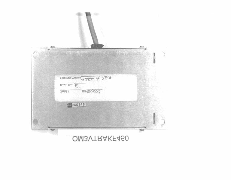
OM3VTRAKF450
Mar 05, 2000UHF-FM Vehicle Tracking System
Equipment Class
TNB - Licensed Non-Broadcast Station Transmitter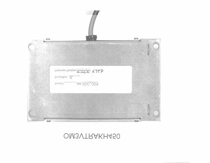
OM3VTRAKH450
Feb 24, 2000UHF-FM VehicleTracking Unit
Equipment Class
TNB - Licensed Non-Broadcast Station Transmitter