OM3VTRAKH450UHF-FM VehicleTracking Unit
Galaxy Tracking Systems L.L.C.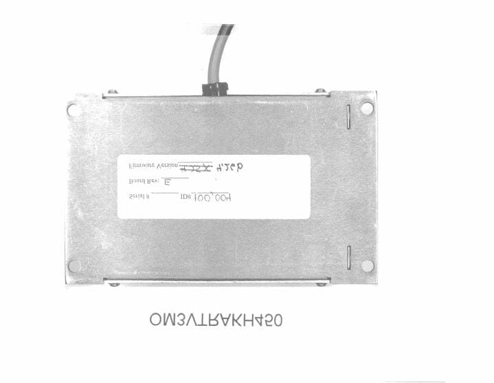
Click to zoom
Application Details
- Equipment Class
- TNB - Licensed Non-Broadcast Station Transmitter
- Date of Grant
- Feb 24, 2000
- Application Purpose
- Original Equipment
- Date of Application
- Dec 29, 1999
- Equipment Note
- UHF-FM VehicleTracking Unit
- Frequency Range
- 450.00000000 - 470.00000000
- Country
- United States
Documents & Files
Document Text
Text extracted from the exhibit documents filed with the FCC. Open a document above to read the original.
Users Manual
Galaxy Tracking Systems, L.L.C.Technical Documentation - VTU 9-1 Use or disclosure of data contained on this sheet is subject to the restriction on the title page of this report. 9.0 Owners/User Manual See Appendix A for “Vehicle Location and Tracking System (VLaTS) Vehicle Tracking Unit (VTU) User’s Guide”.
Users Manual
Appendix A User’s Manual Vehicle Location and Tracking System (VLaTS) Vehicle Transceiver Unit (VTU) User’s Guide Preliminary 7 Sept 1999 Prepared For: Galaxy Tracking Systems, L.L.C. 2500 English Creek Ave., Bldg C Egg Harbor Twp., NJ 08234-5562 (609) 645-0900 FAX (609) 645-3316 Prepared By: Galaxy Scientific Corp. 600 Louis Drive, Suite 202 Warminster, Pa 18974 (215) 672-8005 FAX (215) 672-8708 Email: [email protected] The data contained in this document is proprietary to Galaxy Tracking Systems, L.L.C. Use or disclosure of this data beyond the purposes of the performance of the tasks defined herein without written permission is prohibited. Table of Contents 1INTRODUCTION ..................................................................................................................................1 2SCOPE .................................................................................................................................................1 3APPLICABLE DOCUMENTS ...............................................................................................................1 4SPECIFICATIONS ................................................................................................................................1 5SYSTEM OVERVIEW...........................................................................................................................3 5.1 M OBILE COMPONENTS........................................................................................................................3 5.2 F IXED COMPONENTS...........................................................................................................................3 5.3 RF T RANSMISSION SCHEME................................................................................................................4 5.4 S YSTEM TIMING..................................................................................................................................4 6VTU COMPONENTS............................................................................................................................5 6.1 VTU S YSTEM ENCLOSURE..................................................................................................................5 6.1.1GPS Receiver ..........................................................................................................................5 6.1.2Radio........................................................................................................................................5 6.1.3System Controller ....................................................................................................................6 6.2 A NTENNAS AND CABLES......................................................................................................................6 6.3 O PTIONAL COMPONENTS.....................................................................................................................6 6.3.1Switch Box (Alarms and Indicators) .........................................................................................6 6.3.2Relay Box (Vehicle Controls) ...................................................................................................6 7VTU CONNECTORS AND CONNECTIONS........................................................................................7 7.1 I NPUTS...............................................................................................................................................9 7.2 O UTPUTS.........................................................................................................................................10 7.3 P OWER............................................................................................................................................10 7.4 A NTENNAS........................................................................................................................................10 8VTU OPERATIONS ............................................................................................................................11 8.1 VTU S TARTUP..................................................................................................................................11 8.2 VTU O PERATING MODES..................................................................................................................11 8.2.1OUT OF SERVICE Operating Mode......................................................................................11 8.2.2IN SERVICE Operating Mode ................................................................................................12 Galaxy Tracking Systems, L.L.C.VTU User’s Guide 4 Use or disclosure of data contained on this sheet is subject to the restriction on the title page of this report. Figure 1 - Vehicle Location and Tracking System Architecture .......................................3 Figure 2 - Vehicle Transceiver Unit (VTU).......................................................................5 Figure 3 VTU INPUT PIN DEFINITIONS - 10 pin BROWN Molex Connector .................7 Figure 4 VTU POWER CONNECTOR PIN DEFINITIONS - 4 pin WHITE Molex Connector.................................................................................................................8 Figure 5 VTU OUTPUT PIN DEFINITIONS - 8 pin BROWN Molex Connector ...............9 Galaxy Tracking Systems, L.L.C.VTU User’s Guide 1 Use or disclosure of data contained on this sheet is subject to the restriction on the title page of this report. 1 INTRODUCTION This document is intended to provide a description of the operation and interfaces of the Vehicle Transceiver Unit (VTU). 2 SCOPE This document describes the operation and use of the Vehicle Transceiver Unit (VTU). 3 APPLICABLE DOCUMENTS Vehicle Location and Tracking System (VLaTS) Vehicle Tracking Unit (VTU) Installation Guide Revision 1 24 February 1999 Vehicle Location and Tracking System (VLaTS) Mobile T…
Text truncated - open the document above for the full version.
Users Manual
HIGH SPECIFICATION DATA TRANSCEIVER PART NO. 242-3474-XX0 Second Printing August 1998 Part No. 001-3474-0028-98Printed in U.S.A. HIGH SPECIFICATION DATA TRANSCEIVER PART NO. 242-3474-XX0 Copyright 1998 by the Johnson Data Telemetry Corporation. The Johnson Data Telemetry Corporation designs and manufactures radios and radio modems to serve a wide variety of data communication needs. The Johnson Data Telemetry Corporation produces equipment for the fixed data market including SCADA systems for utilities, petrochemical, waste and fresh water management markets and RF boards for OEM applications in the Radio Frequency Data Capture market. DATA TELEMETRY PRODUCT WARRANTY The manufacturer's warranty statement for this product is available from your product supplier or from the Johnson Data Telemetry Corporation, 299 Johnson Avenue, Box 1733, Waseca, MN 56093-0833. Phone (507) 835-8819. WARNING This device complies with Part 15 of the FCC rules. Operation is subject to the condition that this device does not cause harmful interference. In addition, changes or modification to this equipment not expressly approved by Johnson Data Telemetry Corporation could void the user's authority to operate this equipment (FCC rules, 47CFR Part 15.19). DO NOT allow the antenna to come close to or touch, the eyes, face, or any exposed body parts while the radio is transmitting. DO NOT operate the radio near electrical blasting caps or in an explosive atmosphere. DO NOT operate the radio unless all the radio frequency connectors are secure and any open connectors are properly terminated. DO NOT allow children to operate transmitter equipped radio equipment. SAFETY INFORMATION Proper operation of this radio will result in user exposure below the Occupational Safety and Health Act and Federal Communication Commission limits. The information in this document is subject to change without notice. is a trademark of the Johnson Data Telemetry Corporation. i TABLE OF CONTENTS 1GENERAL INFORMATION 1.1SCOPE OF MANUAL. . . . . . . . . . . . . . . . . . . . . . . . . . . . . . . . . . . . . . . . . . . . . . . . . . . . . . . . . . . . . . . . . . . . . . . . .1-1 1.2EQUIPMENT DESCRIPTION. . . . . . . . . . . . . . . . . . . . . . . . . . . . . . . . . . . . . . . . . . . . . . . . . . . . . . . . . . . . . . . . . .1-1 GENERAL. . . . . . . . . . . . . . . . . . . . . . . . . . . . . . . . . . . . . . . . . . . . . . . . . . . . . . . . . . . . . . . . . . . . . . . . . . . . . . . . . . 1-1 DM3474 SYNTHESIZER PROGRAMMING . . . . . . . . . . . . . . . . . . . . . . . . . . . . . . . . . . . . . . . . . . . . . . . . . . . . . . 1-1 1.3TRANSCEIVER IDENTIFICATION . . . . . . . . . . . . . . . . . . . . . . . . . . . . . . . . . . . . . . . . . . . . . . . . . . . . . . . . . . . .1-1 1.4PART NUMBER BREAKDOWN . . . . . . . . . . . . . . . . . . . . . . . . . . . . . . . . . . . . . . . . . . . . . . . . . . . . . . . . . . . . . . .1-2 1.5ACCESSORIES . . . . . . . . . . . . . . . . . . . . . . . . . . . . . . . . . . . . . . . . . . . . . . . . . . . . . . . . . . . . . . . . . . . . . . . . . . . . . .1-2 1.6FACTORY CUSTOMER SERVICE. . . . . . . . . . . . . . . . . . . . . . . . . . . . . . . . . . . . . . . . . . . . . . . . . . . . . . . . . . . . .1-2 1.7PRODUCT WARRANTY. . . . . . . . . . . . . . . . . . . . . . . . . . . . . . . . . . . . . . . . . . . . . . . . . . . . . . . . . . . . . . . . . . . . . .1-3 1.8REPLACEMENT PARTS. . . . . . . . . . . . . . . . . . . . . . . . . . . . . . . . . . . . . . . . . . . . . . . . . . . . . . . . . . . . . . . . . . . . . .1-3 1.9IF A PROBLEM ARISES . . . . . . . . . . . . . . . . . . . . . . . . . . . . . . . . . . . . . . . . . . . . . . . . . . . . . . . . . . . . . . . . . . . . . .1-4 FACTORY REPAIR . . . . . . . . . . . . . . . . . . . . . . . . . . . . . . . . . . . . . . . . . . . . . . . . . . . . . . . . . . . . . . . . . . . . . . . . . . .1-4 GENERAL SPECIFICATIONS. . . . . . . . . . . . . . . . . . . . . . . . . . . . . . . . . . . . . . . . . . . . . . . . . . . . . . . . . . . . . . . . .1-5 2INSTALLATION 2.1PRE-INSTALLATION CHECKS . . . . . . . . . . . . . . . . . . . . . . . . . . . . . . . . . . . . . . . . . . . . . . . . . . . . . . . . . . . . . . .2-1 2.2INTERFACING WITH DATA EQUIPMENT. . . . . . . . . . . . . . . . . . . . . . . . . . . . . . . . . . . . . . . . . . . . . . . . . . . . .2-1 DM3474 ONLY . . . . . . . . . . . . . . . . . . . . . . . . . . . . . . . . . . . . . . . . . . . . . . . . . . . . . . . . . . . . . . . . . . . . . . . . . . . . . . .2-1 3PROGRAMMING 3.1INTRODUCTION . . . . . . . . . . . . . . . . . . . . . . . . . . . . . . . . . . . . . . . . . . . . . . . . . . . . . . . . . . . . . . . . . . . . . . . . . . . .3-1 3.2DM3474 SYNTHESIZER DATA PROTOCOL . . . . . . . . . . . . . . . . . . . . . . . . . . . . . . . . . . . . . . . . . . . . . . . . . . . .3-1 D-WORD . . . . . . . . . . . . . . . . . . . . . . . . . . . . . . . . . . . . . . . . . . . . . . . . . . . . . . . . . . . . . . . . . . . . . . . . . . . . . . . . . . . .3-1 B-WORD . . . . . . . . . . . . . . . . . . . . . . . . . . . . . . . . . . . . . . . . . . . . . . . . . . . . . . . . . . . . . . . . . . . . . . . . . . . . . . . . . . . .3-2 A-WORD . . . . . . . . . . . . . . . . . . . . . . . . . . . . . . . . . . . . . . . . . . . . . . . . . . . . . . . . . . . . . . . . . . . . . . . . . . . . . . . . . . . .3-2 3.3RECEIVE TO TRANSMIT SEQUENCE . . . . . . . . . . . . . . . . . . . . . . . . . . . . . . . . . . . . . . . . . . . . . . . . . . . . . . . . .3-6 3.4TRANSMIT TO RECEIVE SEQUENCE . . . . . . . . . . . . . . . . . . . . . . . . . . . . . . . . . . . . . . . . . . . . . . . . . . . . . . . . .3-7 4CIRCUIT DESCRIPTION 4.1GENERAL . . . . . . . . . . . . . . . . . . . . . . . . . . . . . . . . . . . . . . . . . . . . . . . . . . . . . . . . . . . . . . . . . . . . . . . . . . . . . . . . . .4-1 INTRODUCTION . . . . . . . . . . . . . . . . . . . . . . . . . .…
Text truncated - open the document above for the full version.
Block Diagram
Galaxy Tracking Systems, L.L.C.Technical Documentation - VTU 2-1 Use or disclosure of data contained on this sheet is subject to the restriction on the title page of this report. 2.0 VTU Block Diagrams 2.1 VTU Components GPS S ubsys tem ( GPS Receiv er) D i gi tal B ase ba nd Subsyst em (Micro Controller) p,v,t ID , stat us Communications Subsyst em (Radio Modem) Packets , Timing da ta / control Feat ur es 3 Freq between ( 450- 4 70 M hz) 960 0 ba ud GM SK m od ulati on For ward Er ror Cor recti on (Hamm ing c od e, Da ta Int er leavi ng) 2 watt transmit power 20 K r an ge GPS VLaTS Vehicle Tracking Unit (VTU) p,v,t, ID,st atus Commands, Timing Stat us I ncl u des: H ar dwar e st at us GPS Tr acki ng s tat us Discretes st atus C onfi g ur ati on, Initializ ation, GPS Cor r ecti ons Vehicl e Movement, SOS, Assistanc e, Car Alarm U naut hor i z ed M ov em ent Ar m ed, SOS, Assistanc e Discretes Indic ators UHF Figure 1 - Vehicle Transceiver Unit (VTU) 2.2 VTU System Enclosure 2.2.1 GPS Receiver Every VTU contains a GPS Receiver and is equipped with a GPS antenna and an antenna cable. The receiver is differentially aided through the RF link to provide vehicle position accuracy to within a few meters and synchronized system time accurate to within .5 ms. The position information is transmitted to the command center at a precise predetermined moment based on system time. The GPS receiver will report a position at 0 degrees latitude and 0 degrees longitude unless it can find and track GPS satellites. This takes less than a minute under normal circumstances, but can take up to a half an hour the first time the VTU is turned on. It is recommended that the VTU equipped vehicle be allowed to remain stationary for 15 minutes, with a clear view of the sky, the first time it is powered up. 2.2.2 Data Transceiver The VTU Data Transceiver is capable of operation on 16 distinct frequencies over the frequency range of 450 to 470 MHz at 2 watts operating within 25kHz channels. VTU Galaxy Tracking Systems, L.L.C.Technical Documentation - VTU 2-2 Use or disclosure of data contained on this sheet is subject to the restriction on the title page of this report. radio can be configured at the factory to operate at other frequencies and channel widths. Frequencies are preset at the factory and selected for operation from the command center via the RF link. 2.2.3 Digital Baseband Board The Digital Baseband Board is the system controller and the heart of the VTU. It integrates the Data Transceiver and GPS Receiver, contains the system logic the overall operation of the VTU. It is comprised of a single board embedded controller equipped with a Motorola 68HC11 microcontroller, 32 Kilobytes of flash ROM, 32 Kilobytes of SRAM and various support components to enable the circuitry to perform the desired tasks. In addition, the Digital Baseband Board is equipped with a MX-COM 909A single chip GMSK data pump modem for the purpose of providing the communications subsystem with modulation and Forward Error Correction (FEC) for data transmission and reception. 2.2.4 Antennas and Cables A GPS Antenna, a UHF antenna, associated cables and power cabling are included with each VTU. GPS antennas are available as permanently mounted units, temporary magnetic mount units or as covert units. Similar options are available for UHF antennas. Refer to the VTU Installation Guide details. 2.3 Optional Components 2.3.1 Switch Box (Alarms and Indicators) As an option, a small switch box can be acquired for installation in VTU equipped vehicles. The box houses the three momentary contact switches for issuing alarms and arming the unauthorized movement sensor and four LED indicators. Three of the indicators display alarm status, the fourth monitors VTU power and transmit activity. The switch box is small enough that it can be mounted unobtrusively in the passenger compartment in such a way that the operator can monitor status, but it will go unnoticed by other occupants (or a thief). 2.3.2 Relay Box (Vehicle Controls) The VTU provide four outputs suitable for controlling relays. With the relays installed in various automotive systems, lights, horn, ignition, etc. the VTU can be controlled or disabled by suitably equipped chase vehicles. Refer to the Mobile Tracking Unit (MTU) User’s Guide. This type of installation is very model or even vehicle specific and is ordinarily left to qualified mechanics or motor pool personnel. Galaxy Tracking Systems, L.L.C.Technical Documentation - VTU 2-3 Use or disclosure of data contained on this sheet is subject to the restriction on the title page of this report. 2.4 VTU Digital Baseband Subsystem Block Diagram JP2 U23/U24 GPS Receiver U3/ U2/ U9 Rx Data Programming Tx Data X1 8 MHz U13 (6,7) U13 (2,3) U13 (4,5) < < < < Buffer JP1, pin 7 Sync Lock JP1, pin 8 Sync Enable JP1, pin 9 Sync Data JP1, pin 10 Sync Clock JP1, pin 11 CD JP1, pin 12 RSSI < U10 (5,6,7) U10 (2,3,4) CD Adj U1 Mc68HC11 Microprocessor PA5 PD3 PD4 PA7 PD0 PD1 DO-D7 DO-D7 U12 Mx909A Modem X2 4.9152 MHz U10(8,9,10) U10(12,13,14) Amplifier Buffer < JP1, pin 13 DEMOD/ Rx out JP1, pin 6 Mod/ Tx in < U15 U28 U29 Splitter Filters Bias Adj DC Adj VTU Digital Board RF Block Diagram Memory Buffer Buffer ComparatorBuffer GMSKIN D A T A T R A N S C E I V E R Tx out < D A T A T R A N S C E I V E R Galaxy Tracking Systems, L.L.C.Technical Documentation - VTU 2-4 Use or disclosure of data contained on this sheet is subject to the restriction on the title page of this report. 2.5 Communications Subsystem/Data Transceiver Block Diagram Galaxy Tracking Systems, L.L.C.Technical Documentation - VTU 2-5 Use or disclosure of data contained on this sheet is subject to the restriction on the title page of this report. Galaxy Tracking Systems, L.L.C.Technical Documentation - VTU 2-6 Use or disclosure of data contained on this sheet is subject to the restriction on the title page of this report. 2.6 GPS Subsystem/GPS Receiver Block Diagram
Cover Letter(s)
Vehicle Location and Tracking System (VLaTS) FCC Part 90 Filing Technical Documentation Vehicle Transceiver Unit (VTU) Revision 0 – 7 December 1999 Prepared For: Galaxy Tracking Systems, L.L.C. 2500 English Creek Ave., Bldg C Egg Harbor Twp., NJ 08234-5562 (609) 645-0900 FAX (609) 645-3316 Prepared By: Galaxy Scientific Corp. 600 Louis Drive, Suite 202 Warminster, Pa 18974 (215) 672-8005 FAX (215) 672-8708 Email: [email protected] The data contained in this document is proprietary to Galaxy Tracking Systems, L.L.C. Use or disclosure of this data beyond the purposes of the performance of the tasks defined herein without written permission is prohibited. TABLE OF CONTENT Sec Title Page Cover/Table of Content- PDF File: “Cover-TOC.pdf” 1.0 Introduction1-1 PDF File: “Operational_Description_part1.pdf” 2.0 VTU Block Diagram2-1 PDF File: “Block_Diagram.pdf” 3.0 Schematics Diagrams3-1 PDF File: “Schematic_part1.pdf”, “Schematic_part2.pdf” 4.0 Circuit Description4-1 PDF File: “Operational_Description_part2.pdf” 5.0 Circuits Determining Frequency5-1 PDF File: “Operational_Description_part2.pdf” 6.0 Circuits Suppressing Spurious 6-1 And Harmonic Emissions PDF File: “Operational_Description_part2.pdf” 7.0 Active Circuits List7-1 PDF File: “Parts_List_part1.pdf”, “Parts_List_part2.pdf 8.0 Alignment Procedures and Performance Testing8-1 PDF File: “Tune_Up.pdf” 9.0 Owner/User Manual9-1 PDF File: “Users_Manual_part1.pdf” 10.0 Identification Label Drawing And Sketch 10-1 PDF File: “ID_Label-Location_Info.pdf” 11.0 Attestation Letter11-1 PDF File: “Attestation Statement.pdf” 12.0 Authorization Letter12-1 PDF File: “Authorization_Letters.pdf” Appendix A: User’s Manual PDF File: “Users_Manual_part2.pdf” Appendix B: High Specification Data Transceiver – Service Manual PDF File: “Data_Transceiver_Service_Manual.pdf”
External Photos
Galaxy Tracking Systems Galaxy Tracking Systems Galaxy Tracking Systems Galaxy Tracking Systems
ID Label/Location Info
Galaxy Tracking Systems, L.L.C.Technical Documentation - VTU 10-1 Use or disclosure of data contained on this sheet is subject to the restriction on the title page of this report. 10.0 Identification Label and Location Section 10 presents two unique identification labels to support two FCC Part 90 filings in the 450 – 470 MHz frequency bands for a 25 kHz channel unit and 12.5 kHz channel unit. The two labels are identified as follows: Label with FCC ID “OM3VTRAKF450” supports the 25 kHz 450 –470 MHz VTU in both the with RS232 and non RS232 data interface configuration. Label with FCC ID “OM3VTRAKH450” supports the 12.5 kHz 450 –470 MHz VTU in both the with RS232 and non RS232 data interface configuration. Galaxy Tracking Systems, L.L.C.Technical Documentation - VTU 10-2 Use or disclosure of data contained on this sheet is subject to the restriction on the title page of this report. VTU Identification Label Model: Unit ID: VTRAKF450 Frequency: 450-470 Power: 2 Watt FCC ID: OM3VTRAKF450 Canada: This device complies with part 15 of the FCC Rules. Operation is subject to the condition that This device does not cause harmful interference. 2.3” 2.3” VTU Identification Label Label Top of VTU Notes Material: White Mylar Adhesive: Perm Adhesive Size: 2.3” x 2.3” Diecut Unit ID: Hand written at factory 2500 English Creek Ave., Bldg II, Egg Harbor Twp., NJ 08234-5562, (609) 645-0900 Galaxy Tracking Systems, L.L.C.Technical Documentation - VTU 10-3 Use or disclosure of data contained on this sheet is subject to the restriction on the title page of this report. VTU Identification Label Model: Unit ID: VTRAKH450 Frequency: 450-470 Power: 2 Watt FCC ID: OM3VTRAKH450 Canada: This device complies with part 15 of the FCC Rules. Operation is subject to the condition that This device does not cause harmful interference. 2.3” 2.3” VTU Identification Label Label Top of VTU Notes Material: White Mylar Adhesive: Perm Adhesive Size: 2.3” x 2.3” Diecut Unit ID: Hand written at factory 2500 English Creek Ave., Bldg II, Egg Harbor Twp., NJ 08234-5562, (609) 645-0900
Internal Photos
Galaxy Tracking Systems Galaxy Tracking Systems Galaxy Tracking Systems Galaxy Tracking Systems Galaxy Tracking Systems
Operational Description
Galaxy Tracking Systems, L.L.C.Technical Documentation - VTU 1-1 Use or disclosure of data contained on this sheet is subject to the restriction on the title page of this report. 1.0 Introduction This document is intended to provide supporting documentation towards the Galaxy Tracking Systems, L.L.C. efforts in achieving FCC Part 90 Certification for the Vehicle Transceiver Unit (VTU) marketed under the name V-Trak TM . This documentation supports VTUs containing a UHF Data Transceiver operating in the 450 to 470 MHz frequency bands for 25 kHz and the 12.5 kHz channel operation. To achieve 25 verses 12.5 kHz channel operation requires factory installation of an appropriately configured UHF Data Transceiver deck within the VTU. Besides the UHF Data Transceiver no other physical differences exist between the 25 kHz and 12.5 kHz VTUs. VTUs are also available in two data interface configurations 1) with RS232 data interface and 2) without RS232 data interface. The with RS232 interface allows VTU operation with a digital display to enhance man machine interaction. 1.1 System Overview A typical configuration of Galaxy’s vehicle tracking system is illustrated below. CENTRAL COMMAND CENTER (CCC) CENTRAL COMMAND CENTER (CCC) CENTRAL BROADCASTING UNIT (CBU) GPS SATELLITE NETWORK FIXED TRACKING UNIT (FTU) FTU FTU DIGITAL DATA LINK (DDL) DDL DDL DDL Private Vehicle Transceiver Unit (VTU) Mobile Tracking unit (MTU) RF RF RF RF RF Fleet Vehicle Tranceiver Unit (VTU) GPS GPS RF Figure 1 - Vehicle Location and Tracking System Architecture 1.1.1 Mobile Components The VTU is the mobile component of Galaxy’s vehicle location and tracking system. Each VTU contains a GPS receiver to determine location, and a UHF Data Transceiver for communications. VTUs run directly off of vehicular battery power and are small enough to be easily hidden. Galaxy Tracking Systems, L.L.C.Technical Documentation - VTU 1-2 Use or disclosure of data contained on this sheet is subject to the restriction on the title page of this report. Vehicles equipped with VTUs can be commanded to continuously report their position, speed, and status. For anti-theft and security related applications, the VTU can provide limited remote control of vehicle systems (e.g., lights, horn or ignition), as well as automated and manual alarms. 1.1.2 Fixed Components The tracking system’s infrastructure is comprised a powerful transmitter, Central Broadcasting Unit (CBU), and a host of fixed receivers, Fixed Tracking Units (FTUs), placed strategically throughout the area of operations to ensure uninterrupted communications to member vehicles. The CBU operates under the direct control of the Central Command Center (CCC) which provides the primary operator interface to command and control the system. The CBU transmits aiding data, system timing data and VTU commands at precise intervals synchronized to GPS time. Every VTU command requires an acknowledgment back to the CCC. The exact time and interval at which the VTU is to transmit its response(s) is contained in the original VTU command. Vehicle (VTU) transmissions are received by FTU(s) and forwarded by direct cable connection or telephone line back to the CCC. 1.1.3 RF Transmission Scheme Galaxy’s system currently supports sixteen radio channels. Each channel is comprised of a receive / transmit frequency pair within the radio’s operating frequency range. Each channel is divided using a Time Division Multiple Access (TDMA) transmission scheme that begins on a one-hour boundary and repeats every 30 seconds. Each 30-second cycle is divided into five six-second frames. The frames are further divided into 100 msec “slots”. The first six time slots of each frame are allocated to CBU transmissions. The remaining time slots are allocated dynamically to specific VTUs under control of the command center. 1.1.4 System Timing Accurate time is required to maintain the TDMA transmission scheme employed for UHF communications. All system components are synchronized to within a few milliseconds of each other using the GPS 1 PPS output pulse. Galaxy Tracking Systems, L.L.C.Technical Documentation - VTU 1-3 Use or disclosure of data contained on this sheet is subject to the restriction on the title page of this report. 1.2 VTU Specification Sheet V-Trak™ GPS-based Vehicle Location and Tracking Unit All-in-one Vehicle Tracking Unit V-Trak™ is a self-contained Automatic Vehicle Location device, for use with the Vehicle Location and Tracking System (VLATS). V- Trak™ can be used for: • Fleet Tracking and Management- Taxis, buses, armored cars, delivery vehicles. • Personal Safety and Security: Use in case of emergency to summon police, medical or mechanical assistance. V-Trak™ includes everything necessary for accurate vehicle tracking: differential GPS receiver, digital wireless RF link, and micro- processor control. It requires only 12 VDC vehicle power, a GPS antenna and UHF antenna to operate. Advanced TDMA Communications Link: V-Trak™ incorporates a high-speed bi- directional communications link. Precise timing allows tens of thousands many V-Trak™ units to operate simultaneously. The communications link incorporates advanced Forward Error Correction (FEC) and data interleaving, providing superior performance in difficult urban environments V-Trak™ features: • SOS Alarm: Pressing this notifies Command Center of emergency and exact location • Unauthorized movement alarm: vehicle movement (theft) notifies Command Center. • xternal Vehicle Controls: Controls lights, horn or shuts off engine remotely. Galaxy Tracking Systems, L.L.C.Technical Documentation - VTU 1-4 Use or disclosure of data contained on this sheet is subject to the restriction on the title page of this report. Specifications UHF Receiver: Frequency:Multiple frequency operation within band Frequency Band:450 - 470 MHz band typical, others available from 403- 512 MHz Modulation Format:GMSK Deviation:+/-5 kHz Transmission Rate:19,200 Baud, 7-bit even parity, 1 …
Text truncated - open the document above for the full version.
Operational Description
Galaxy Tracking Systems, L.L.C.Technical Documentation - VTU 4-1 Use or disclosure of data contained on this sheet is subject to the restriction on the title page of this report. 4.0 VTU Circuit Description 4.1 Introduction The main subsystems of the VTU are OEM Data Transceiver, OEM GPS Receiver, and Digital Baseband Board. A block diagram of critical RF circuitry are depicted in Section 4. 4.2 Digital Baseband Board The Digital Baseband Board handles all I/0 external to the VTU and all I/O functions to and from the OEM GPS Receiver and OEM Data Transceiver. 4.2.1 Microprocessor (U1), RAM/ROM (U3,U2,U9) The Microprocessor in conjunction with the RAM/ROM memory executes programming to control all I/O functions, process receive and transmit data, control all functioning on the Digital Baseband Board and with the Data Transceiver and GPS Receiver. A 8 MHz clock generates pulses used by the microprocessor to execute programming, clock I/O and program the synthesizer. Programming information is fed out on enable, data, and clock lines and is distributed by buffers to other digital components. The microprocessor provides receiver and transmitter control information including Synchronization Enable (PA5/JP1, pin 8), Synchronization Data (PD3/JP1, pin 9), Synchronization Clocking (PD4/JP1, pin 10) through digital buffers (U13) to the Data Transceiver. The Data Transceiver is mated to the Digital Baseband Board via the 14 pin JP1 connector. The microprocessor receives a Synchronization Lock indication (JP1, pin 7) directly from the Data Transceiver. The microprocessor …
Text truncated - open the document above for the full version.
Contact Information
Applicant
John Rybarczyk(Manager of Contracts)
Technical Contact
M. Flom Associates, Inc.William H Graff
[email protected]480 926 3100
3356 N. San Marcos Place · Chandler, Arizona · United States
Non-Technical Contact
M. Flom Associates, IncMorton Flom
[email protected]480 926 3100
Test Firm
M. Flom Associates, Inc.Morton Flom
Technical Specifications
| # | Rule Parts | Frequency Range | Power Output | Emission | Tolerance |
|---|---|---|---|---|---|
| 1 | 90.210 | 450 MHz - 470 MHz | 2 W | 11K0F1D | 2.5000000000 ppm |
Other Applications from Galaxy Tracking Systems L.L.C.
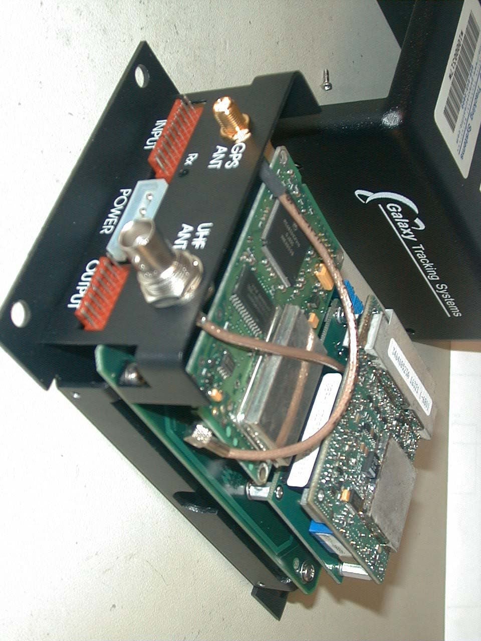
OM3VTRAKH150
Jun 22, 2004VEHICLE TRACKING UNIT
Equipment Class
TNB - Licensed Non-Broadcast Station Transmitter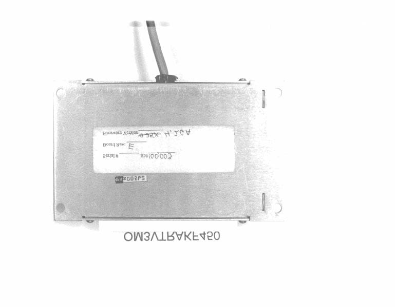
OM3VTRAKF450
Mar 05, 2000UHF-FM Vehicle Tracking System
Equipment Class
TNB - Licensed Non-Broadcast Station Transmitter