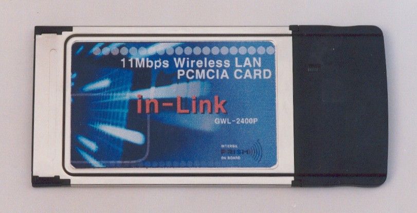
OM9GWL2400PWireless LAN Card
Genotech Co., Ltd.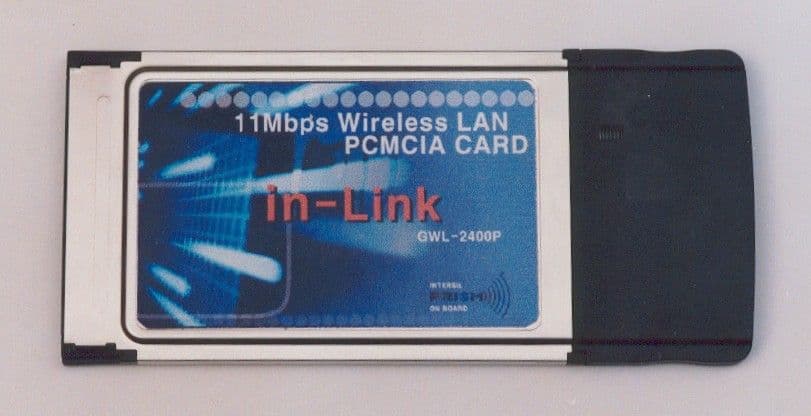
Click to zoom
Application Details
- Equipment Class
- DSS - Part 15 Spread Spectrum Transmitter
- Date of Grant
- Jun 13, 2001
- Application Purpose
- Original Equipment
- Date of Application
- Jun 13, 2001
- Equipment Note
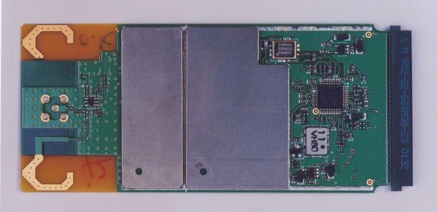
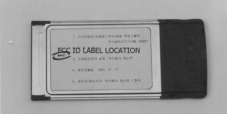
- Wireless LAN Card
- Frequency Range
- 2400.00000000 - 2462.00000000
- Company
- Genotech Co., Ltd.
- Country
- South Korea
Documents & Files
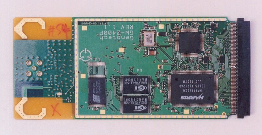
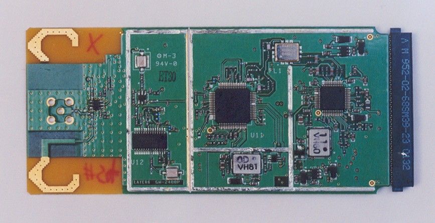
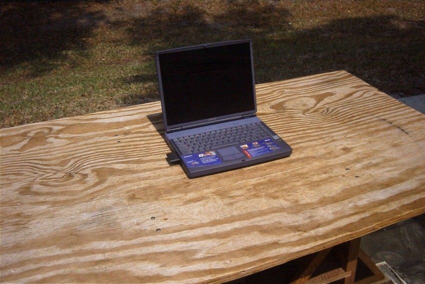
Document Text
Text extracted from the exhibit documents filed with the FCC. Open a document above to read the original.
Users Manual
GWL-2400P ( WIRELESS LANCARD ) GENOTECH CO . LTD 1 NOTICES This device complies with Part 15 of the FCC rules. Operation is subject to the following two conditions. 1. This device may not cause harmful interference. 2. This device must accept any interference received, including interference that may cause undesired operation. NOTE: This equipment has been tested and found to comply with the limits for a Class B digital device, pursuant to Part 15 of the FCC rules. These limits are designed to provide reasonable protection against harmful interference in a residential installation. This equipment generates, uses and can radiate radio frequency energy and, if not installed and used in accordance with the instruction manual, may cause harmful interference to radio communications. However, there is no guarantee that interference will not occur in a particular installation. If this equipment does cause harmful interference to radio or television reception, which can be determined by turning the equipment off and on, the user is encouraged to try to correct the interference by one or more of the following measures: • Reorient or relocate the receiving antenna • Increase the separation between the equipment and the receiver • Connect the equipment into an outlet on a circuit different from that to which the receiver is connected • Consult the dealer or an experienced ratio/TV technician for help WARNING! Any changes or modifications of equipment not expressly approved by Intersil could void the user’s authority to operate the equipment. 2 GWL-2400P Technical Support Your comments and suggestion help us to improve the quality and usefulness of our documentation, you may response to the following contact e-mail. If you encounter problems when installing or using this product, or would like more information about our other products, you can contact us with the telephone numbers listed below. Useful information TEL:82-2-3281-2490 FAX:82-2-3281-2491 E-Mail: [email protected] World Wide Web: http://www.genoi.com #308 GUNKOOK BLG, 288-1, DOKSAN-DONG GUMCHON-GU, SEOUL, KOREA 3 Important Safety Information • Read these simple guidelines. Breaking the rules may be dangerous or illegal. GENOTECH will not be responsible for any damages caused by breaking the rules. • Wireless LAN Card described in this document is approved for use in a wireless local area network. • Remember to make backup copies of important data. • GENOTECH Wireless PCMCIA LAN card supports 3.3V Notebook computers only. • When you are transferring data, keep your laptop computer stationary Roaming between access points (AP) may break the connection. • Only qualified service personnel must repair the equipment. • All wireless devices may get interference, which could affect performance. • Use only the region settings appropriate for the area where the wireless LAN Card is used at the present time. Using the card in any other region or with an incorrect region setting is prohibited and may be illegal. • Operation of any radio transmitting equipment, including a Wireless LAN Card, may cause interference with the functionality of inadequately protected medical devices. • Do not use the wireless LAN Card on aircraft. • Do not use the wireless LAN Card at a refueling point. • Do not use the wireless LAN Card near inflammable materials or chemicals. • Do not use the wireless LAN Card where blasting is in progress. • Do not use the wireless LAN Card when the use of wireless device may cause interference or danger. • Do not use the wireless LAN Card where the use of cellular terminals is prohibited. • Microwave oven degrades the performance of wireless LAN drastically. So do not use the wireless LAN Card in the environment where Microwave oven is being used. 4 CONTENT 1. GENERAL 1-1 Overview of IEEE 802.11 1-2 Characteristic 1-3 Composition 2. SPECIFICATION 2-1 General Specification 2-2 Network Specification 2-3 Environmental Specification 2-4 Physical Characteristics 3. INSTALLATION 3-1 Installation Procedure 3-2 Uninstallation Method 3-3 Configuration utility 5 1. GENERAL 1-1 Overview of IEEE 802.11 The IEEE 802.11 specification is a standard for wireless connectivity for fixed, portable, and moving stations within a local area. The IEEE 802.11 standard describes the services required by a compliant device to operate within an “ad hoc” or “infrastructure” network, as well as dealing with the issues related to mobility within those networks. Spread spectrum techniques are used to tolerate mobility and multipath effects. They are also a requirement for compliance with FCC, ETSI and those of other regulatory authorities when operating within the Industrial, Scientific, and Medical (ISM) frequency band. An ad hoc communications network is created quickly and informally for a temporary time period. An infrastructure network usually requires more planning so that wireless stations can communicate over longer distances through access points, and may also communicate with existing wired LANs using portals. The IEEE 802.11 standard describes Media Access Control (MAC) procedures. The principal method of communication is the Carrier Sense Multiple Access with Collision Avoidance (CSMA-CA) protocol. Using this protocol, each station senses the communications medium (RF channel), and does not transmit until the channel is clear. This avoids collisions and minimizes the re-transmission of subsequent packets. The standard also supports the operation of a station within a wireless LAN that may coexist with several overlapping wireless LANs. To accomplish this, a scheme of channelization and spread spectrum techniques is used. Direct Sequence (DSSS) and Frequency Hopping (FHSS) spread spectrum techniques are supported by the standard and both operate in the 2.4 to 2.4835GHz frequency band (the unlicensed ISM band). An infrared technique is also supported for indoor applications. The standard supports a 1 and 2Mbps data rate for both DSSS and FHSS and has recentl…
Text truncated - open the document above for the full version.
Operational Description
1. GENERAL 1-1 Overview of IEEE 802.11 The IEEE 802.11 specification is a standard for wireless connectivity for fixed, portable, and moving stations within a local area. The IEEE 802.11 standard describes the services required by a compliant device to operate within an “ad hoc” or “infrastructure” network, as well as dealing with the issues related to mobility within those networks. Spread spectrum techniques are used to tolerate mobility and multipath effects. They are also a requirement for compliance with FCC, ETSI and those of other regulatory authorities when operating within the Industrial, Scientific, and Medical (ISM) frequency band. An ad hoc communications network is created quickly and informally for a temporary time period. An infrastructure network usually requires more planning so that wireless stations can communicate over longer distances through access points, and may also communicate with existing wired LANs using portals. The IEEE 802.11 standard describes Media Access Control (MAC) procedures. The principal method of communication is the Carrier Sense Multiple Access with Collision Avoidance (CSMA-CA) protocol. Using this protocol, each station senses the communications medium (RF channel), and does not transmit until the channel is clear. This avoids collisions and minimizes the re-transmission of subsequent packets. The standard also supports the operation of a station within a wireless LAN that may coexist with several overlapping wireless LANs. To accomplish this, a scheme of channelization and spread spectrum techniques is used. Direct Sequence (DSSS) and Frequency Hopping (FHSS) spread spectrum techniques are supported by the standard and both operate in the 2.4 to 2.4835GHz frequency band (the unlicensed ISM band). An infrared technique is also supported for indoor applications. The standard supports a 1 and 2Mbps data rate for both DSSS and FHSS and has recently introduced a high data rate standard supporting 5.5 and 11Mbps DSSS using Complementary Code Keying (CCK) modulation. The standard has also specified the requirements and services that enable private and secure communications to occur. 1-2 CHARACTERISTIC • The GWL-2400P is wireless LAN adapter cards that provide wireless connection between computers. • The GWL-2400P is designed to operate with IEEE 802.11 (wireless LAN International Standard) wireless compliant radio cards and uses a CSMA/CA (Collision Sense Multiple Access with Collision Avoidance) algorithm as the media access scheme, which makes high speed communication (with minimal collision probability) possible. • The GWL-2400P supports DSSS (Direct Sequence Spread Spectrum) physical layer. This is a radio technique, which scrambles the data prior to transmission and uses a correlation technique on receiver to improve the signal to noise ratio and makes it possible to communicate in the office having a wall and a compartment. • The GWL-2400P for Notebook PC is small and portable as a roaming function is provided for users who need network services while maintaining mobility. • The GWL-2400P has an LED (Light Emitting Diode ) on the part of the card. • The yellow LED will illuminate when the power is supplied and the card is inserted properly. • The GWL-2400P support various network software. The network driver is provided to support network software such as Windows 95(OSR2)/98, and Windows NT 4.0. 1-3 COMPOSITION • Link-i LAN CARD (PC Card Type II, PCMCIA V 2.1, JEIDA 4.1) • Installation CD • Manual
Schematics
G ENOTECH TITLE: REV: DATE: SHEET: DRAWN BY::ENGINEER: G WL-2400P B 1 OF 4 G ENOTECH TITLE: RE V: DATE: SHEET: DRAWN BY::ENGINEER: G WL-2400P B 2 OF 4 G ENOTECH TITLE: REV: DATE: SHEET: DRAWN BY::ENGINEER: G WL-2400P B 3 OF 4 G ENOTECH TITLE: REV: DATE: SHEET: DRAWN BY::ENGINEER: G WL-2400P B 4 OF 4
Test Report
APPLICANT: GENOTECH CO., LTD. FCC ID: OM9GWL2400P TABLE OF CONTENTS TEST REPORT CONTAINING: PAGE 1.............TEST EQUIPMENT LIST & TEST PROCEDURE PAGE 2.............TEST PROCEDURES CONTD. PAGE 3.............STATEMENT ABOUT ANTENNA AND PRODUCT DESC. PAGE 4-6...........POWERLINE CONDUCTED INTERFERENCE DATA PAGE 7-8...........6.0dB BANDWIDTH & POWER OUTPUT PAGE 9.............METHOD OF MEASURING RF CONDUCTED SPURIOUS EMISSIONS & SPURIOUS EMISSIONS AT ANTENNA TERMINALS PAGE 10............RADIATION INTERFERENCE TEST DATA PAGE 11............METHOD OF MEASURING RADIATION INTERFERENCE PAGE 12............RADIATED SPURIOUS EMISSIONS – CLASS B PAGE 13-14.........RADIATED SPURIOUS EMMISSIONS INTO ADJACENT RESTRICTED BAND. PAGE 15-18.........POWER SPECTRAL DENSITY & PROCESSING GAIN EXHIBIT ATTACHMENTS: EXHIBIT 1...........FCC ID LABEL SAMPLE EXHIBIT 2...........SKETCH OF FCC ID LABEL LOCATION EXHIBIT 3A..........FRONT VIEW EXTERNAL PHOTO EXHIBIT 3B..........REAR VIEW EXTERNAL PHOTO EXHIBIT 3C..........COMPONENT SIDE INTERNAL PHOTO EXHIBIT 3D..........COPPER SIDE INTERNAL PHOTO EXHIBIT 4...........BLOCK DIAGRAM EXHIBIT 5A-5D.......SCHEMATICS EXHIBIT 6A-6B.......CIRCUIT DESCRIPTION EXHIBIT 7A-7O.......INSTRUCTION MANUAL EXHIBIT 8A-8B.......PROCESSING GAIN DATA EXGUBUT 9...........TEST SETUP PHOTOGRAPH APPLICANT: GENOTECH CO., LTD. FCC ID: OM9GWL2400P REPORT #: G\GENOTECH\334K1\334K1RPT.doc TABLE OF CONTENTS LIST TEST EQUIPMENT LIST 1. Spectrum Analyzer: HP 8566B-Opt 462, S/N 3138A07786, w/ preselector HP 85685A, S/N 3221A01400, Quasi-Peak Adapter HP 8565OA, S/N 3303A01690 & Preamplifier HP 8449B-OPT H02, S/N 3008A00372 Cal. 1/19/01 2. Biconnical Antenna: Eaton Model 94455-1, S/N 1057, Cal 3/15/00 3. Biconnical Antenna: Electro-Metrics Model BIA-25, S/N 1171 Cal. 3/16/01 4. Log-Periodic Antenna: Electro-Metrics Model EM-6950, S/N 632 Cal. 3/15/00 5. Log-Periodic Antenna: Electro-Metrics Model LPA-30, S/N 409 Cal. 3/15/00 6. Double-Ridged Horn Antenna: Electro-Metrics Model RGA-180, 1-18 GHz, S/N 2319 7. 18-26.3GHz Systron Donner Standard Gain Horn #DBE-520-20 8. Horn 40-60GHz: ATM Part #19-443-6R 9. Line Impedance Stabilization Network: Electro-Metrics Model EM-7820, w/NEMA Adapter S/N 2682 Cal. 3/16/01 10. Temperature Chamber: Tenney Engineering Model TTRC, S/N 11717-7 Cal. 1/21/01 11. Frequency Counter: HP Model 5385A, S/N 3242A07460 Cal 11/20/00 12. Peak Power Meter: HP Model 8900C, S/N 2131A00545, Cal. 1/26/01 13. Open Area Test Site #1-3meters Cal. 12/22/99 14. Signal Generator: HP 8640B, S/N 2308A21464 Cal. 11/21/00 15. Signal Generator: HP 8614A, S/N 2015A07428 16. Passive Loop Antenna: EMCO Model 6512, 9KHz to 30MHz, S/N 9706-1211 Cal. 6/10/00 17. Dipole Antenna Kit: Electro-Metrics Model TDA-30/1-4, S/N 153 Cal. 11/24/00 18. AC Voltmeter: HP Model 400FL, S/N 2213A14499 Cal. 2/1/01 19. Digital Multimeter: Fluke Model 8012A, S/N 4810047 Cal 9/21/99 20. Digital Multimeter: Fluke Model 77, S/N 43850817 Cal 11/16/00 21. Oscilloscope: Tektronix Model 2230, S/N 300572 Cal 2/1/01 TEST PROCEDURE GENERAL: This report shall NOT be reproduced except in full without the written approval of TIMCO ENGINEERING, INC. Shielded interface cables were used in all cases except for cables connecting to the telephone line and the power cords. A test program was run which simulated a normal data transmission on a network. POWER LINE CONDUCTED INTERFERENCE: The procedure used was ANSI STAN- DARD C63.4-1992 using a 50uH LISN. Both lines were observed with the UUT transmitting. The bandwidth of the spectrum analyzer was 10kHz with an appropriate sweep speed. The ambient temperature of the UUT was 99ºF with a humidity of 22%. APPLICANT: GENOTECH CO., LTD. FCCID: OM9GWL2400P REPORT #: G\GENOTECH\334K1\334K1RPT.doc PAGE #: 1 TEST PROCEDURES CONTINUED BANDWIDTH 6.0dB: The measurements were made withe the spectrum analyz- er's resolution bandwidth(RBW)=1.0MHz and the video bandwidth(VBW) =3.0MHz and the span set as shown on page 8. POWER OUTPUT: The RF power output was measured at the antenna feed point using a peak power meter. ANTENNA CONDUCTED EMISSIONS: The RBW=100KHz, VBW=300KHz and the span set to 10.0MHz and the spectrum was scanned from 30MHz to the 10th Harmonic of the fundamental. Above 1.0GHz the resolution bandwidth was 1.0MHz and the VBW = 3.0MHz and the span to 50MHz. RADIATION INTERFERENCE: The test procedure used was ANSI STANDARD C63.4-1992 using a HEWLETT PACKARD spectrum analyzer with a prese- lector. The bandwidth(RBW) of the spectrum analyzer was 100kHz up to 1GHz and 1.0MHz above 1GHz with an appropriate sweep speed. The VBW above 1.0GHz was = 3.0MHz. The analyzer was calibrated in dB above a microvolt at the output of the antenna. The ambient temperature of the UUT was 99°F with a humidity of 22%. APPLICANT: GENOTECH CO., LTD. FCCID: OM9GWL2400P REPORT #: G\GENOTECH\334K1\334K1RPT.doc PAGE #: 2 PRODUCT DESCRIPTION: This device is a wireless LAN adapter card that provides wireless connection between computers. monopole antenna FREQUENCY RANGE: 2.4-2.4835 GHz SUPPORT BIT RATES: 11 Mbps CCK, 5.5 Mbps CCK, 2 Mbps DQPSK, 1 mPBS dbsk SPREADING: DSSS (Direct Sequence Spread Spectrum) CHIP RATE: 11 Mcps ANTENNA: Internal antenna MEDIA ACCESS PROTOCOL: CSMA/CA (Collission Avoidance) with ACK APPLICANT: GENOTECH CO., LTD. FCCID: OM9GWL2400P REPORT #: G\GENOTECH\334K1\334K1RPT.DOC PAGE #: 3 CPU with PCMIA Card installed APPLICANT: GENOTECH CO., LTD. FCC ID: OM9GWL2400P NAME OF TEST: POWER LINE CONDUCTED INTERFERENCE RULES PART NUMBER: 15.107(a) REQUIREMENTS: .45 - 30 MHz 250 uV OR 47.96 dBuV TEST PROCEDURE: ANSI STANDARD C63.4-1992. The spectrum was scanned from .45 to 30 MHz. TEST DATA: THE HIGHEST EMISSION READ FOR LINE 1 WAS 35.1 uV @ 8.01 MHz. THE HIGHEST EMISSION READ FOR LINE 2 WAS 28.5 uV @ 8.55 MHz. THE GRAPHS IN PAGES 5-6 REPRESENT THE EMISSIONS TAKEN FOR THIS DEVICE. TEST RESULTS: Both lines were observed. The measurements in- dicate that the unit DOES appear to meet the FCC requirements for this class o…
Text truncated - open the document above for the full version.
Test Report
15.247(c) Method of Measuring RF Conducted Spurious Emissions /--------\ |HP | |Spectrum| |Analyzer| |8566B | \--------/ | /-----------\ /-----------------\ | |TRANSMITTER| | 50 OHM RESISTIVE| | | UNDER TEST|------| LOAD |-----\ /-------/ \-----------/ \-----------------/ | | |/-------\| \| |/ \-------/ ATTENUATOR NAME OF TEST: SPURIOUS EMISSIONS AT ANTENNA TERMINALS REQUIREMENTS: Emissions must be at least 20dB down from the highest emission level within the authorized band as measured with a 100KHz RBW. EMISSION dB BELOW FREQUENCY CARRIER ___MHz___ _________ 2412.0 0.00 4824.0 -76.11 7236.0 -84.71 9648.0 -95.81 12060.0 -102.81 2437.0 0.00 4874.0 -77.80 7311.0 -80.30 9748.0 -87.00 12185.0 -100.00 2462.0 0.00 4924.0 -84.30 7386.0 -75.90 9848.0 -87.40 12310.0 -102.10 NOTE: THE SPECTRUM WAS SCANNED TO THE TENTH HARMONIC. APPLICANT: GENOTECH CO., LTD. FCCID: OM9GWL2400P REPORT #: G\GENOTECH\334K1\334K1RPT.doc PAGE #: 9 15.247(c),15.205 &15.209(b) Field_strength_of_spurious_emissions: REQUIREMENTS: FIELD STRENGTH FIELD STRENGTH S15.209 of Fundamental: of Harmonics 30 - 88 MHz 40 dBuV/m @3M 902-928MHz 88 -216 MHz 43.5 2.4-2.4835GHz 216 -960 MHz 46 127.38dBuV/m @3m 54 dBuV/m @3m ABOVE 960 MHz 54dBuV/m EMISSIONS RADIATED OUTSIDE OF THE SPECIFIED FREQUENCY BANDS, EXCEPT FOR HARMONICS, SHALL BE ATTENUATED BY AT LEAST 50 dB BELOW THE LEVEL OF THE FUNDAMENTAL OR TO THE GENERAL RADIATED EMISSION LIMITS IN 15.209, WHICHEVER IS THE LESSER ATTENUATION. REQUIREMENTS: Emissions that fall in the restricted bands (15.205) must be less than 54dBuV/m otherwise the spurious and harmonics must be attenuated by at least 20dB. TEST DATA: Tuned Frequency MHz Emission Frequency MHz Meter Reading dBuv Ant. Polarity Coax Loss dB Correction Factor dB Field Strength dBuv/m Margin dB 2,412.20 2,412.20 69.3 H 3.70 28.98 101.98 25.40 2,437.00 2,437.00 69.2 H 3.70 28.98 101.88 25.50 2,462.00 2,462.00 69.4 H 3.70 28.98 102.08 25.30 Antenna Gain Intentional Radiator Emissions METHOD OF MEASUREMENT: The procedure used was ANSI STANDARD C63.4-1992 & the Guidance on Measurements for Direct Sequence Spread Spectrum Systems. Measurements were made at the open field test site of TIMCO ENGINEERING INC. located at 849 N.W. State Road, Newberry, FL 32669. APPLICANT: GENOTECH CO., LTD. FCCID: OM9GWL2400P REPORT #: G\GENOTECH\334K1\334K1RPT.doc PAGE #: 10 2.993(a)(b) 2.993(a)(b) Continued Field_strength_of_spurious_emissions: Method of Measuring Radiated Spurious Emissions * Tuned, Calibrated Antenna which may be raised from 1-4 Meters above ground and changed in polarization. Equipment placed 80 cm above ground on a rotatable platform. APPLICANT: GENOTECH CO., LTD. FCCID: OM9GWL2400P REPORT #: G\GENOTECH\334K1\334K1RPT.DOC PAGE #: 11 Spectrum Analyzer DUT DUT Antenna CPU with PCMIA 3 Meter * APPLICANT: GENOTECH CO., LTD. FCC ID: OM9GWL2400P NAME OF TEST: RADIATED SPURIOUS EMISSIONS RULES PART NO.: 15.109(a) - Class B Computing Device REQUIREMENTS: 30-88 MHz 40.0 dBuV/m measured at 3 meters 88-216 MHz 43.5 dbuV/m 216-960 MHz 46.0 dbuV/m ABOVE 960 MHz 54.0 dbuV/m TEST CONFIGURATION: DELL COMPUTER MODEL #: DIMENSION XPS M200S DELL MONITOR FCC ID: AK8CPD155SFT1 IBM KEYBOARD P/NO. 1391401 MICROSOFT MOUSE FCC ID: C3KKMP3 EPSON EX-800 PRINTER FCC ID: BKM9A8P84PA TEST DATA: EMISSION METER READING COAX ANTENNA FIELD FREQUENCY AT 3 METERS LOSS CORRECTION STRENGTH MARGIN ANT. MHz dBuV dB FACTOR dB dBuV/m@3m dB POL. 117.30 13.90 0.80 9.20 23.90 19.60 V 297.80 13.70 1.40 15.56 30.66 15.34 V 386.00 11.60 1.40 16.59 29.59 16.41 V 397.20 14.40 1.40 16.92 32.72 13.28 H TEST PROCEDURE: ANSI STANDARD C63.4-1992 The spectrum was scanned from 30 to 1000 MHz. The unit was measured at Timco Engineering Inc. 849 N.W. State Road 45, Newberry, FL 32669. TEST RESULTS: The unit DOES appear to meet the FCC requirements. PERFORMED BY:___Joe Scoglio__________________ DATE: May 17, 2001 APPLICANT: GENOTECH CO., LTD. FCCID: OM9GWL2400P REPORT #: G\GENOTECH\334K1\334K1RPT.DOC PAGE #: 12 APPLICANT: GENOTECH CO., LTD. FCC ID: OM9GWL2400P NAME OF TEST: RADIATED SPURIOUS EMISSIONS INTO ADJACENT RESTRICTED BAND REQUIREMENTS: Emissions that fall in the restricted bands (15.205). These emissions must be less than or equal to 500 uV/m (54 dBuV/m). TEST PROCEDURE: An in band field strength measurement of the fundamental emissions using the RBW and detector function required by C63.4-2000 and FCC rules. The procedure was repeated with an average detector and a plot made. The calculated field strength in the adjacent restricted band is presented below. -100.30 dBm - from Plot + 29.21 dB - ACF + 1.1 dB - Coax Loss + 10.0 dB - ___________ - 59.99 dBm +107.00 ___________ 47.01 dBuV APPLICANT: GENOTECH CO., LTD. FCCID: OM9GWL2400P REPORT #: G\GENOTECH\334K1\334K1RPT.DOC PAGE #: 13 APPLICANT: GENOTECH CO., LTD. FCC ID: OM9GWL2400P NAME OF TEST: POWER SPECTRAL DENSITY RULES PART NUMBER: 15.247(d) REQUIREMENTS: The peak level measured must be no greater than +8.0dBm. DATA: The plots are on the following pages as 16-18. The level at 2437.00 MHz 2417.00 MHz 2472.48 MHz From Plot: - 66.40 dBm -66.90 dBm -66.10 dBm + 20.00 dB ATT +20.00 dB ATT +20.00 dB ATT + 35.00 CF +35.00 CF +35.00 CF Calculation: - 11.40 dBm -11.90 dBm -11.10 dBm NAME OF TEST: PROCESSING GAIN RULES PART NUMBER: 15.247(e) REQUIREMENTS: DATA: The processing gain information supplied by the manufacturer is 10.0dB. See Pages 8A-8B for processing gain test methods and data. APPLICANT: GENOTECH CO., LTD. FCCID: OM9GWL2400P REPORT #: G\GENOTECH\334K1\334K1RPT.DOC PAGE #: 15
Contact Information
Applicant
Soo-Wan Kim(President)
Test Firm
Timco Engineering, Inc.S Sanders
Technical Specifications
| # | Rule Parts | Frequency Range | Power Output |
|---|---|---|---|
| 1 | 15C | 2.40 GHz - 2.46 GHz | 26.00 mW |
Other Applications from Genotech Co., Ltd.
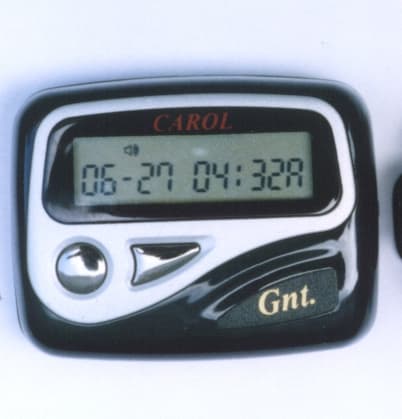
OM9GNT901
Sep 23, 1999Pager Receiver
Equipment Class
CXX - Communications Rcvr for use w/ licensed Tx and CBs