OMD803-001Wireless Auditory Assistance Device
Listen Technologies Corporation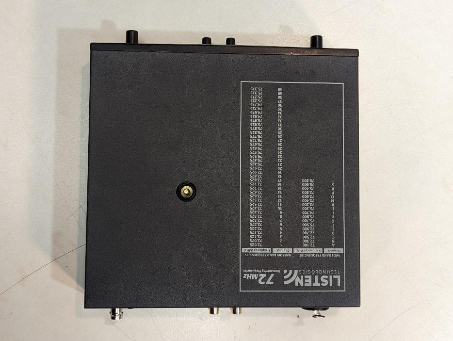
Click to zoom
Application Details
- Equipment Class
- GAT - Part 15 Auditory Assistance Device (Transmitter)
- Date of Grant
- Feb 18, 2024
- Application Purpose
- Original Equipment
- Date of Application
- Feb 18, 2024
- Equipment Note
- Wireless Auditory Assistance Device
- Frequency Range
- 75.90000000 - 75.90000000
- Country
- United States
Documents & Files
Document Text
Text extracted from the exhibit documents filed with the FCC. Open a document above to read the original.
Users Manual
User Manual LT-800-072 Stationary RF Transmitter LT-803-072 Stationary RF Transmitter LT-800-216 Stationary RF Transmitter www.listentech.com 1 Block Diagram Quick Reference Troubleshooting Warranty Table of Contents 2 3 3 3 4 5 6 9 10 11 12 12 13 14 14 15 16 17 19 19 20 21 21 22 2 LT-800-072 Contents LT-803-072 Contents LT-816-072 Contents LT-800-072LA-207 LT-803-072LA-207 LT-800-216LA-207 Package Contents 3 LT-800-072LT-803-072LT-800-216 RF RF Frequency Range72.025 - 75.950 MHz216.025 - 216.9875 MHz Number of Channels17 wide band, 40 narrow band3 wide band19 wide band, 38 narrow band Frequency Accuracy Transmitter Stability50 PPM Output Power80,000uV at 3 m AntennaVarious Antennas available Antenna ConnectorBNC ComplianceFCC Part 15, Industry CanadaFCC Part 90, Industry Canada Audio System Frequency Response System Signal to Noise Ratio 80 dB SQ enabled; 60 dB SQ disabled80 dB SQ enabled; 50 dB SQ disabled System Distortion Audio Input 1 Audio Input 2 ContourCuts and boosts frequencies above 5 kHz Controls Front Panel Rear Panel Compression ratio for audio processor Programming Indicators SQ and Processing RF Power Test Tone Power Power Supply Type Power Supply Input Power Supply Output Power Supply Connector Power Supply Compliance Physical Color Shipping Weight Rack Mounting Environmental Temperature - Operation Temperature - Storage Humidity0 to 95% Relative Humidity, non condensing 4 Block Diagram 5 which channel in a headset and voice and clockwise for occasionally lights the Power power supply unbalanced audio to these phono connectors, input level match the level of your not used to increase or connection of a microphone or combination connector accepts phono connectors; and the website for details on antennas Remove rubber plug and screw Quiet mode is to lock on current Back Panel: Connections & Settings Front Panel: Controls & Displays Quick Reference 6 Setup Instructions Unpack the Product Mount in Rack (if necessary) NOTE: If rack mounting, you will need to use a rear connection antenna. Connect Power Plug the power supply into the power connector on the back Connect Antenna remote antenna connected to the rear of the unit, do not antenna options, or refer to the Listen website for remote antenna options, www.listentech.com. Select Phonak Compatibility (if necessary) Rubber Plug antenna connected through top of unit 1 2 3 4 5 7 Setup Instructions (cont.) To Select Phonak Mode (LT-800 only): Select Channel Mode (if necessary) To Select Expanded Mode (LT-800 only): Set SQ (Super Quiet) and Process Features (SQ available on LT-800 only): To Disable or Enable SQ and Process Features: Once in the program mode, disabled the features as desired, let the transmitter Program icon Process is enabled 6 7 8 XLR Wiring Line Phantom Power Setup Instructions (cont.) power power power Set RF Power are operating multiple transmitters in the same environment, it is best to set the transmitters output power to its lowest level to reduce the Connect Audio Inputs Input 1 Plug your balanced or unbalanced audio source into Input 2 8 9 9 Operating Instructions Press Test Tone button here NOTE: The LT-800 is shipped with only limited channels (Basic Mode). To select from all channels (Expanded Mode) refer to page 11. Power Unit On Select a Channel Lock on Channel Test Tone (if necessary) Lock icon 1 2 3 4 10 Adjust Mix Level Adjust Audio Input Level Adjust Contour Audio Control 1 2 3 11 People are accustomed to listening to low noise, high fidelity audio • • • Process Mode input levels by raising or lowering the signal level accordingly to provide a where a consistent sound level is important and the input levels vary Basic and Expanded Mode (LT-800 only) SQ Summary performance by at least with older version Listen products products be enabled for both the transmitter and receivers permit operation with older Listen products or other Listen SQ (Super Quiet) - Improving Your Listening Experience 12 cable that is better or worse than this value. Please check with the cable vendor or manufacturer for exact specifications. When designing and installing your system, keep in mind that the location of both the transmitting and CAUTION: When installing antennas, ensure the antenna is clear of power lines. www.listentech.com, RF Reception Maximization Strategies Coaxial Cable 13 audio through the headphone or via the speaker and choose a channel If you are using multiple channels follow this process: Same Space Distributed Spacing over a large area, you can achieve more simultaneous broadcast Notes in regard to using 72 MHz and 216 MHz systems: Channel Selection Wide Band Listen recommends that you always use a wide band channel unless you need to narrow band receivers from band channels have lower noise than their narrow band At 72MHz operates on 17 wide band • Letters= Wide Band At 216MHz 14 Wideband frequencies are indicated in highlighted 72 MHz Compatibility Chart 15 Wideband frequencies are The highlighted channels also indicated those channels can be accessed when in 216 MHz Compatibility Chart 16 Wideband frequencies are indicated in also indicated those channels available in the Frequency (MHz)Listen 216.0121A1 216.0252A41 216.0373A2 216.0621B21 216.0752B42 216.0883B4 216.1131C5 216.1252C43 216.1373C22 216.1621D23 216.1752D44 216.1883D8 216.2139 216.22545 216.23824 216.2621F25 216.2752F46 216.2873F12 216.31213 216.32547 216.33826 216.3631H27 216.3752H48 216.3873H16 216.4121J17 216.4252J49 216.4383J18 216.5121K61 216.5252K29 216.5373K62 216.56228 216.57552 216.58864 216.6131M65 216.6252M53 216.6373M81 216.6621N82 216.6752N54 216.6883N68 216.7131P69 216.7252P55 216.7383P83 216.7621R84 216.7752R56 216.7873R72 216.8121S73 216.8252S57 216.8383S76 216.8631T85 216.8752T58 216.8873T86 216.91277 216.92559 216.93888 216.9631V79 216.9752V60 216.9883V80 Phonak Frequency Chart 17 Troubleshooting The LT-800/LT-803 has no power. There is no audio or the audio level is too low. The audio is distorted. There is hum …
Text truncated - open the document above for the full version.
Attestation Statements
Federal Communications Commission Authorization and Evaluation Division 7435 Oakland Mills Road Columbia, MD 21046 USA Date: February 15, 2024 Ref: Attestation Statements Part 2.911(d)(5)(i) Filing FCC ID: OMD803-001 Listen Technologies Corporation (“the applicant”) certifies that the equipment for which authorization is sought is not “covered” equipment prohibited from receiving an equipment authorization pursuant to section 2.903 of the FCC rules. Sincerely, Tracy Bathurst CTO Listen Technologies Corporation 14912 Heritage Crest Way, Bluffdale UT 84065 www.listentech.com
Attestation Statements
Listen Technologies Corporation 14912 Heritage Crest Way, Bluffdale UT 84065 www.listentech.com Federal Communications Commission Authorization and Evaluation Division 7435 Oakland Mills Road Columbia, MD 21046 USA Date: February 15, 2024 Ref: Attestation Statements Part 2.911(d)(5)(ii) Filing FCC ID: OMD803-001 Listen Technologies Corporation (“the applicant”) certifies that, as of the date of the filing of the application, the applicant is not identified on the Covered List (as a specifically named entity, or any of its subsidiaries or affiliates) as an entity producing “covered” equipment. Sincerely, Tracy Bathurst CTO
Attestation Statements
Federal Communications Commission Authorization and Evaluation Division 7435 Oakland Mills Road Columbia, MD 21046 USA Date: February 14, 2024 Ref: Attestation Statements Part 2.911(d)(7) Filing FCC ID: OMD803-001 Listen Technologies Corporation (“the applicant”) certifies that, as of the date of the filing of the application, we designate ourselves as the U.S. agent for service of process. Designated U.S. Agent Information: FRN: 0009694597 Company Name: Listen Technologies Corporation Address: 14912 Heritage Crest Way, Bluffdale UT 84065-4818 Contact Person: Tracy Bathurst Tel.: 801-542-7710 Email: [email protected] Sincerely, Tracy Bathurst CTO
Cover Letter(s)
Authority to Act as Agent FCC February 14, 2024 Federal Communications Commission Authorization and Evaluation Division 7435 Oakland Mills Road Columbia, MD 21046, USA SUBJECT: FCC Application for FCC ID: OMD803-001 To Whom It May Concern: We, the undersigned, hereby authorize Jason Stewart of VPI Technology at 313 W. 12800 S,. Suite 311, Draper UT 84020 to act as our agent and on our behalf, to apply to the Federal Communications Commission on our equipment. Any and all acts carried out by VPI Technology on our behalf shall have the same effect as acts of our own. This is to advise that we are in full compliance with the Anti- Drug Abuse Act. We, the applicant, are not subject to a denial of federal benefits pursuant to Section 5301 of the Anti-Drug Act of 1988, 21 USC853a, and no party to the application is subject to a denial of federal benefits pursuant to that section. Regards, By: Tracy Bathurst Title: CTO On behalf of Listen Technologies Corporation
Cover Letter(s)
February 14, 2024 Federal Communications Commission 7435 Oakland Mills Road Columbia MD 21046 Subject: Request for Confidentiality FCC ID: OMD803-001 To Whom It May Concern: Pursuant to the provisions of Sections 0.457 and 0.459 of the Commission’s rules (47 CFR §§ 0.457, 0.459), we are requesting the Commission to withhold the following attachments as confidential document from public disclosure indefinitely. Schematic Block Diagram Operational Description Above mentioned document contains detailed system and equipment description are considered as proprietary information in operation of the equipment. The public disclosure of above documents might be harmful to our company and would give competitor an unfair advantage in the market. Best Regards Tracy Bathurst CTO Listen Technologies Corporation
External Photos
313 West 12800 South, Suite 311, Draper, UT 84020 • (801) 260-4040 LT803_ExtPho.docx Page 1 of 6 PROPRIETARY External Photographs Photograph 1 – Front View of the EUT 313 West 12800 South, Suite 311, Draper, UT 84020 • (801) 260-4040 LT803_ExtPho.docx Page 2 of 6 PROPRIETARY Photograph 2 – Back View of the EUT 313 West 12800 South, Suite 311, Draper, UT 84020 • (801) 260-4040 LT803_ExtPho.docx Page 3 of 6 PROPRIETARY Photograph 3 – Top View of the EUT 313 West 12800 South, Suite 311, Draper, UT 84020 • (801) 260-4040 LT803_ExtPho.docx Page 4 of 6 PROPRIETARY Photograph 4 – Bottom View of the EUT 313 West 12800 South, Suite 311, Draper, UT 84020 • (801) 260-4040 LT803_ExtPho.docx Page 5 of 6 PROPRIETARY Photograph 5 – Left Side View of the EUT 313 West 12800 South, Suite 311, Draper, UT 84020 • (801) 260-4040 LT803_ExtPho.docx Page 6 of 6 PROPRIETARY Photograph 6 – Front/Right Side View of the EUT
Internal Photos
313 West 12800 South, Suite 311, Draper, UT 84020 • (801) 260-4040 LT803_IntPho.docx Page 1 of 4 PROPRIETARY Internal Photographs Photograph 1 – Top View of PCB as placed in the Housing Rear Antenna Port RF Circuit 313 West 12800 South, Suite 311, Draper, UT 84020 • (801) 260-4040 LT803_IntPho.docx Page 2 of 4 PROPRIETARY Photograph 2 – Bottom View of the PCBA 313 West 12800 South, Suite 311, Draper, UT 84020 • (801) 260-4040 LT803_IntPho.docx Page 3 of 4 PROPRIETARY Photograph 3 – Close-Up of RF Circuit Photograph 4 – Back side of RF Card 313 West 12800 South, Suite 311, Draper, UT 84020 • (801) 260-4040 LT803_IntPho.docx Page 4 of 4 PROPRIETARY Photograph 5 – Front Panel PCB Front Side Photograph 6 – Front Panel PCB Back Side
RF Exposure Info
313 West 12800 South, Suite 311, Draper, UT 84020 • (801) 260-4040 LT803_MPE.docx Page 1 of 2 PROPRIETARY 47 C.F.R. Part 1, Subpart I, Section 1.1310 47 C.F.R. Part 2, Subpart J, Section 2.1091 Maximum Permissible Exposure Calculations FCC ID: OMD803-001 EUT Device Category = General Population/Uncontrolled Exposure EUT consists of one radio transmitting operating at a frequency of: 72.10 MHz, 72.9 MHz, or 75.9 MHz MPE Summary: According subpart 1.1307 (b)(1) and 2.1091 systems operating under the provisions of this section shall be operated in a manner that ensures the public is not exposed to RF energy level in excess of the communication guidelines. Limits for General Population/Uncontrolled Exposure Limits for General Population/Uncontrolled Exposure Frequency Range (MHz) Electric Field Strength (V/m) Magnetic Field Strength (A/m) Power Density (mW/cm2) Averaging Time (Minutes) 0.3-1.34 614 1.63 *(100) 30 1.34-30 824/f 2.19/f *(180/f2) 30 30-300 27.5 0.073 0.2 30 300-1500 / / f/1500 30 1500-100,000 / / 1.0 30 f = frequency in MHz; * = Plane-wave equivalent power density Calculated Formulary: Predication of MPE limit at a given distance S = power density (in appropriate units, e.g. mW/cm 2 ) R = distance to the center of radiation of the antenna (appropriate units, e.g., cm) PG = EIRP 313 West 12800 South, Suite 311, Draper, UT 84020 • (801) 260-4040 LT803_MPE.docx Page 2 of 2 PROPRIETARY MPE and Limit are calculated as follows: f (MHz) Field Strength (dBuV/m) EIRP (mW) Power Density (mW/cm^2) Limit (mW/cm^2) ∆ 72.1 96.0 1.19 0.000237 0.2 0.1998 75.9 93.6 0.69 0.000137 0.2 0.1999 Result: The device meets FCC MPE limit at 20 cm for General Population/Uncontrolled Exposure as specified in 47 CRF §1.1310 and §2.1091.
Test Report
lllitsiffiUJ!U!li Im FUDA ANALYTICAL TESTING GROUP Report Number: FT-20230913095-En-3 Page 4 of5 1.2.2. Test steps 1) Install the tested antenna in a free space, and the connection arrangement between the tested antenna and the measurement system is shown in Figure 3; 2) Calibrate the measurement system; 3) Connect the measurement system to the tested antenna and measure the gain within the operating frequency range. 4) Provide 72MHz antenna gain data. 1.2.3. Antenna _gain calibration data Frequency (MHz) Antenna gain (dBi) 72 2.80 :::::----.._ Second Floor, Fuhua Building Fudan University, No. 525, Guoquan Road, Yangpu District, Shanghai, China. Service Hotline: 021-61996230 E-mail:[email protected]
Test Report
Radiation Pattern report Antenna: LA-122 – 72-76 MHz telescoping dipole Reference Orientation Frequency : 74 MHz Pea k Gain: 2.18 dBi Orientation Frequency : 74 MHz Pea k Gain: 2.18 dBi Orientation Frequency: 74 MHz Pea k Gain: 2.16 dBi
Test Report
SecondFloor,FuhuaBuildingFudanUniversity,No.525,GuoquanRoad,YangpuDistrict,Shanghai,China. ServiceHotline:021-61996230E-mail:[email protected] TestReport SampleNameHelicalAntenna Client SEOWONELECTRONICS (YANTAI)CO.,LTD ReportNumberFT-20230913095-En-9 ShanghaiFudaTestingTechnologyGroupCO.,Ltd. 报告查询访问官网 SecondFloor,FuhuaBuildingFudanUniversity,No.525,GuoquanRoad,YangpuDistrict,Shanghai,China. ServiceHotline:021-61996230E-mail:[email protected] ReportNumber:FT-20230913095-En-9Page1of5 SampleNameHelicalAntenna SampleQuantity1SampleBatch/ SampleStatusIntactSampleNumberFT230913095 Client SEOWONELECTRONICS(YANTAI)CO.,LTD Communication InformationofClient NO.16YuanshengRoad,LaishanDistrict,Yantai TestCategoryCommissionTest SampleArrivalDate2023.09.25 TestCycle2023.09.26-2023.10.26 StandardsandMethodsPleaserefertonextpage(s). TestResults Thisreportonlyprovidesthemeasuredvalues.Seethe summarypageoftestresultsinthisreportfordetails. Remarks Model : LA-123 ; ERPCode : M716A0 ; PARTNAME:HELICALANTENNA; Supplie:HUIZHOUFENGLIYUANANTENNA CO.,LTD ; Address : HuZhenMiddleSchoolbefore500 meters , BoluoCounty,Huizhoucity,Guangdongprovince (Providedbytheentrustingparty) Drafter : Signer : Reviewer:IssuedDate:2023-11-02 SecondFloor,FuhuaBuildingFudanUniversity,No.525,GuoquanRoad,YangpuDistrict,Shanghai,China. ServiceHotline:021-61996230E-mail:[email protected] ReportNumber:FT-20230913095-En-9Page2of5 TestResult(s): No.TestitemTestResultFrequencyTestMethod 1Directionalpattern Asfollows72MHzRequirementsoftheclient 2AntennagainAsfollows72MHzRequirementsoftheclient 1.Testitemsandresults 1.1.Directionmap 1.1.1.Testlayoutdiagram Figure1:Layoutofdirectionalmapmeasurement 1.1.2.Teststeps 1)Installthetestedantennainafreespace,andtheconnectionarrangementbetween thetestedantennaandthemeasurementsystemisshowninFigure1; 2)Calibratethemeasurementsystem; 3)Connectthemeasurementsystemtothetestedantennaandmeasurethedirectional patternwithintheoperatingfrequencyrange. 4)Providea72MHzdirectionalmap. 1.1.3.Testinginstruments InstrumentNameModelandcalibrationinformation Networkanalyzer 101423 Equipmentnumber:2023F31-10-4637582001 Nextcalibrationtime:2024-06-08 AnjiOpenField E-28 Equipmentnumber:EH-H26/23 Nextcalibrationtime:2028-04-28 SecondFloor,FuhuaBuildingFudanUniversity,No.525,GuoquanRoad,YangpuDistrict,Shanghai,China. ServiceHotline:021-61996230E-mail:[email protected] ReportNumber:FT-20230913095-En-9Page3of5 1.1.4.H-planedirectionalmap Figure2:H-planedirectiondiagram 1.2.Antennagain 1.2.1.Testlayoutdiagram Figure3:Layoutofantennagainmeasurement SecondFloor,FuhuaBuildingFudanUniversity,No.525,GuoquanRoad,YangpuDistrict,Shanghai,China. ServiceHotline:021-61996230E-mail:[email protected] ReportNumber:FT-20230913095-En-9Page4of5 1.2.2.Teststeps 1)Installthetestedantennainafreespace,andtheconnectionarrangementbetween thetestedantennaandthemeasurementsystemisshowninFigure3; 2)Calibratethemeasurementsystem; 3)Connectthemeasurementsystemtothetestedantennaandmeasurethegainwithin theoperatingfrequencyrange. 4)Provide72MHzantennagaindata. 1.2.3.Antennagaincalibrationdata Frequency(MHz)Antennagain(dBi) 722.66 ***TheEndoftheReport*** SecondFloor,FuhuaBuildingFudanUniversity,No.525,GuoquanRoad,YangpuDistrict,Shanghai,China. ServiceHotline:021-61996230E-mail:[email protected] ReportNumber:FT-20230913095-En-9Page5of5 AdditionalInstructionsoftheReport 1.TheReportwouldbeinvalidwithout“SpecialSealforReportofShanghaiFudaTesting TechnologyGroupCO.,Ltd.”. 2.Anyinstitutionisnotpermittedtoduplicatethereport,ifneededpleasesubmitaformal application. 3.Anyobjectiontothereportshouldbeinterposedin10daysfromthedateofreportisissued. Overduewouldnotbeadmissible. 4.Thereportisonlyresponsibleforthesampleprovidedbytheapplicant.Thesamplewillbekept for30daysafterthedateofreportisissued. 5.Thecompanyshallperformthedutyofconfidentialitytothetechnicaldocuments,report, contractdocumentsandotherbusinesssecretsoftheapplicant. 6.Whenthereportisnotstampedwiththequalificationidentificationmark(CMA),itindicates thattherelevantprojectshavenotobtainedthequalificationidentification.Thedataand resultsareonlyusedforscientificresearch,teachingandinternalqualitycontrol,notforsocial justice.TheChineseversionshallprevail.
Test Report
313 West 12800 South, Suite 311 Draper, UT 84020 (801) 260-4040 Test Report Certification FCC ID OMD800-002 OMD803-001 Equipment Under Test LT-800-072, LT-803-072 Test Report Serial No V069122_01 Dates of Test June 13, 14 and 19th, 2023 Report Issue Date July 20, 2023 Test Specifications: Applicant: FCC Part 15, Subpart C Listen Technologies 14912 Heritagecrest Way Bluffdale, UT 84065-4818 U.S.A. 313 West 12800 South, Suite 311, Draper, UT 84020 • (801) 260-4040 V069122_01_ListenTech_LT-800-072_FCC_C.docx Page 2 of 37 PROPRIETARY Certification of Engineering Report This report has been prepared by VPI Laboratories, Inc. to document compliance of the device described below with the requirements of Federal Communications Commission (FCC) Part 15, Subpart C. This report may be reproduced in full. Partial reproduction of this report may only be made with the written consent of the laboratory. The results in this report apply only to the sample tested. Applicant Listen Technologies Manufacturer Listen Technologies Brand Name Listen Model Number LT-800-072, LT-803-072 FCC ID OMD800-002 OMD803-001 On this 20 th day of July 2023, I, individually and for VPI Laboratories, Inc., certify that the statements made in this engineering report are true, complete, and correct to the best of my knowledge, and are made in good faith. Although NVLAP has accredited the VPI Laboratories, Inc. EMC testing facilities, this report must not be used to claim product certification, approval, or endorsement by NVLAP, NIST, or any agency of the federal government. VPI Laboratories, Inc. Tested by: Benjamin N. Antczak Reviewed by: Jason Stewart 313 West 12800 South, Suite 311, Draper, UT 84020 • (801) 260-4040 V069122_01_ListenTech_LT-800-072_FCC_C.docx Page 3 of 37 PROPRIETARY Revision History Revision Description Date 01 Original Report Release July 20, 2023 313 West 12800 South, Suite 311, Draper, UT 84020 • (801) 260-4040 V069122_01_ListenTech_LT-800-072_FCC_C.docx Page 4 of 37 PROPRIETARY Table of Contents 1 Client Information ................................................................................................................................. 5 1.1 Applicant ....................................................................................................................................... 5 1.2 Manufacturer ................................................................................................................................. 5 2 Equipment Under Test (EUT) ............................................................................................................... 6 2.1 Identification of EUT .................................................................................................................... 6 2.2 Description of EUT ....................................................................................................................... 6 2.3 EUT and Support Equipment ........................................................................................................ 7 2.4 Interface Ports on EUT ................................................................................................................. 8 2.5 Modification Incorporated/Special Accessories on EUT .............................................................. 8 2.6 Deviation from Test Standard ....................................................................................................... 8 3 Test Specification, Methods and Procedures ........................................................................................ 9 3.1 Test Specification .......................................................................................................................... 9 3.2 Methods & Procedures .................................................................................................................. 9 3.3 Test Procedure ............................................................................................................................ 10 4 Operation of EUT During Testing ...................................................................................................... 11 4.1 Operating Environment ............................................................................................................... 11 4.2 Operating Modes ......................................................................................................................... 11 4.3 EUT Exercise Software ............................................................................................................... 11 5 Summary of Test Results .................................................................................................................... 12 5.1 FCC Part 15, Subpart C .............................................................................................................. 12 5.2 Result .......................................................................................................................................... 12 6 Measurements, Examinations and Derived Results ............................................................................ 13 6.1 General Comments ...................................................................................................................... 13 6.2 Test Results ................................................................................................................................. 13 6.3 Sample Measurement Calculations ............................................................................................. 30 7 Test Procedures and Test Equipment .................................................................................................. 31 7.1 Conducted Emissions at Mains Ports .......................................................................................... 31 7.2 Direct Connection at the Antenna Port Tests .............................................................................. 32 7.3 Radiated Emissi…
Text truncated - open the document above for the full version.
Test Setup Photos
313 West 12800 South, Suite 311, Draper, UT 84020 • (801) 260-4040 LT803_Tsup.docx Page 1 of 4 PROPRIETARY Test Set Up Photographs Photograph 1: Front View Radiated Emissions, Worst Case – Below 1000 MHz Configuration Photograph 2: Back View Radiated Emissions Worst Case 30 MHz to 1000 Configuration 313 West 12800 South, Suite 311, Draper, UT 84020 • (801) 260-4040 LT803_Tsup.docx Page 2 of 4 PROPRIETARY Photograph 3: Front View Conducted Emissions Worst-Case Configuration Photograph 4: Back View Conducted Emissions Worst-Case Configuration 313 West 12800 South, Suite 311, Draper, UT 84020 • (801) 260-4040 LT803_Tsup.docx Page 3 of 4 PROPRIETARY Reference Test Set Up Photographs Photograph 5: Reference Photo of Test Setup for Emissions Below 30 MHz Photograph 6: Reference Photo of Test Setup for Emissions From 30 MHz to 1000 MHz 313 West 12800 South, Suite 311, Draper, UT 84020 • (801) 260-4040 LT803_Tsup.docx Page 4 of 4 PROPRIETARY Photograph 7: Reference Photo of Test Setup for Emissions Above 1000 MHz
Contact Information
Applicant
Tracy Alan Bathurst(Chief Technology Officer)
Test Firm
VPI TechnologyJason Stewart
[email protected]801-495-2310
Technical Specifications
| # | Rule Parts | Frequency Range | Power Output |
|---|---|---|---|
| 2 | 15.237 | 75.9 MHz - 75.9 MHz | - |
Other Applications from Listen Technologies Corporation
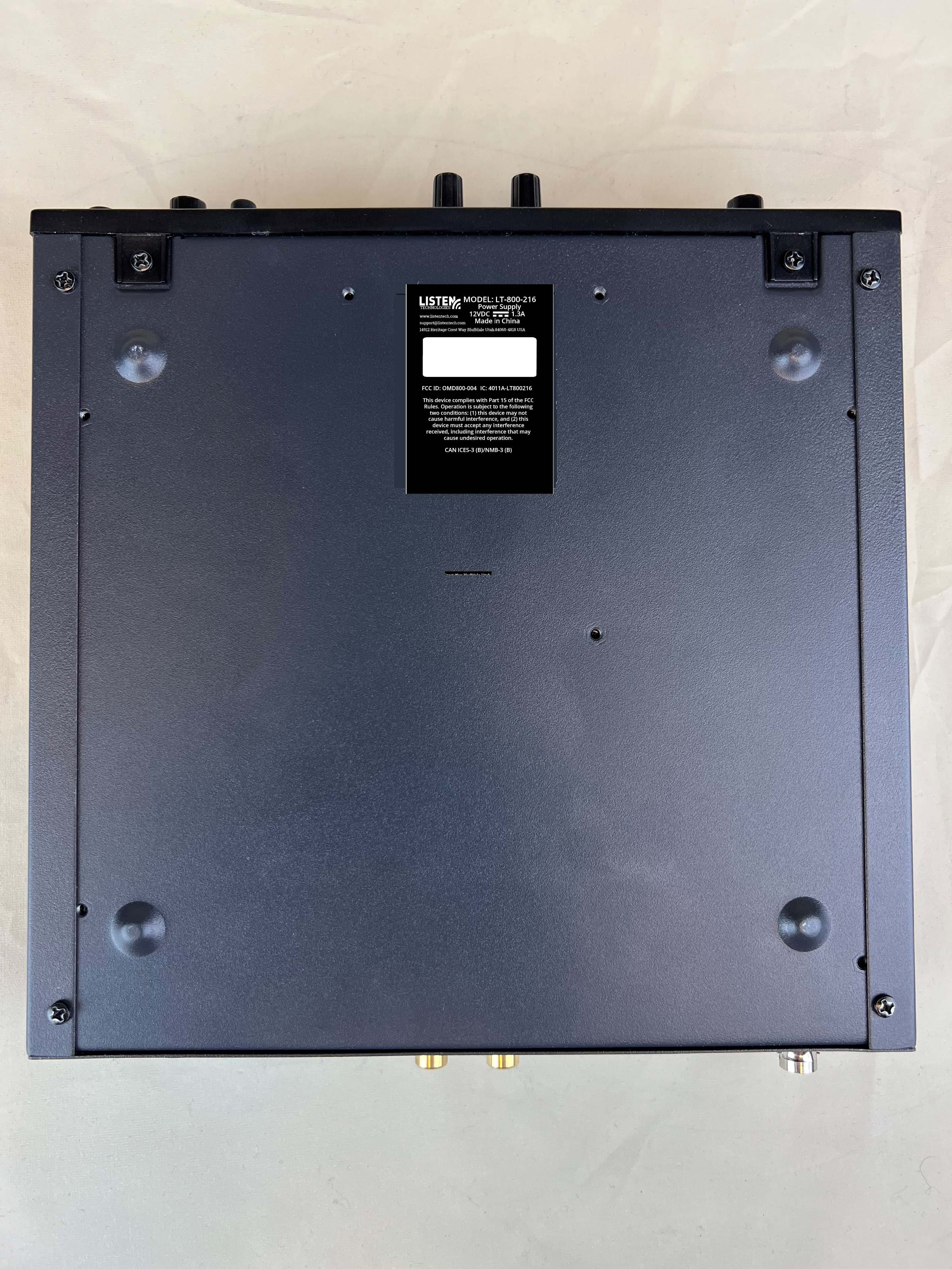
OMD800-004
Aug 05, 2024Assisted Listening Technology Device
Equipment Class
TNB - Licensed Non-Broadcast Station Transmitter
OMDT216001
Dec 16, 2013ListenPoint Assistive Listening Kit (216 MHz)
Equipment Class
TNB - Licensed Non-Broadcast Station TransmitterOMD800-003
Jun 06, 2005LPRS Model LT-800B-216
Equipment Class
TNB - Licensed Non-Broadcast Station Transmitter
OMDMSF0001
Nov 20, 2003Assistive Listenting System for Hard of Hearing
Equipment Class
TNB - Licensed Non-Broadcast Station Transmitter
OMD800-001
Aug 26, 2001Auditory Assistance Transmitter
Equipment Class
GAT - Part 15 Auditory Assistance Device (Transmitter)