OMDT216001ListenPoint Assistive Listening Kit (216 MHz)
Listen Technologies Corporation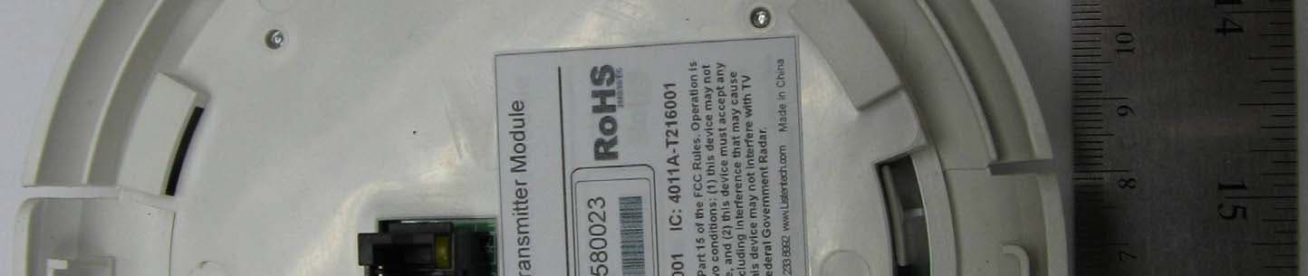
Click to zoom
Application Details
- Equipment Class
- TNB - Licensed Non-Broadcast Station Transmitter
- Date of Grant
- Dec 16, 2013
- Application Purpose
- Original Equipment
- Date of Application
- Dec 16, 2013
- Equipment Note
- ListenPoint Assistive Listening Kit (216 MHz)
- Frequency Range
- 216.02500000 - 216.97500000
- Country
- United States
Documents & Files
Document Text
Text extracted from the exhibit documents filed with the FCC. Open a document above to read the original.
Users Manual
Welcome! Let’s get started. What you will need: Screwdriver Marking Pencil Hole Saw What’s in the box: LPT-T216 ListenPoint ® ALS Module (216MHz) Mounting Platform Mounting Hardware * If you did not receive all listed parts please call Listen Technologies Corporation - See back page for contact information. Plan and Prepare for Installation a. Evaluate the room for optimal placement of the T216 ALS Transmitter. b. Decide where you want to install your T216 ALS Transmitter. Use a pencil to mark the center of the Transmitter’s location. c. Using the mounting template provided; cut a hole in the ceiling with a hole saw. Items to Remember * The distance between the T216 ALS Transmitter and the Room Module should only be a maximum of 50 ft. (15 m). The T216 ALS Transmitter broadcasts an FM signal. FM signal will travel * through walls and other visual obstructions. Appropriate attention needs to be paid to placement of the transmitter for optimal privacy and performance within the room. * Do not cut into ceiling without safely checking above the hole location for the presence of any wires, ducting, or any other obstruction that may exist. Transmitter Installation Pull Cable a. Run the Cat-5e cable from your ListenPoint ® Room Module (RM) to the hole at the desired location for your T216 ALS Transmitter. This may require additional tools to pull the cable through any obstructions. b. Cable should be pulled through the open slot of the mounting platform. c. Mount the ALS Mounting Platform included with the T216 ALS Transmitter on the ceiling using the supplied mounting hardware. * May be attached to an electrical box, or directly to the ceiling or ceiling tile. Attach ALS Transmitter to Room Module and Mount 1 2 3 4 SPEAKERS LISTE 4 LISTEN BUS N BUS PAGING 6-12VDC N.C. COM N.O. RELAY T O CU INPUT INPUT OUTPUT 19VDC Connect Transmitter to RM a. Connect the Cat-5e cable to the “LISTEN BUS” port on the RM. Connect the other end of the Cat-5e cable directly to the T216 ALS Transmitter via the port. b. Mount the T216 ALS Transmitter onto the ALS Transmitter Mounting Plat- form. The Transmitter will slide in and snap into place. * To snap into place, simply align notches and turn clockwise until it snaps. Installation is complete! Configure Your System Adjust Menu Items on the ListenPoint ® Control Unit To access CU Menu Items follow this sequence: a. First, ensure that your ListenPoint® System has the latest updates in firmware (See included card with Update Information). b. Press the CU control knob. c. Scroll down to the “Optional Module” Tab and push the control knob. Top Level Menu Speaker Control Paging Microph ones Auto Select On Top Lev el Menu Speaker Control Paging Microphones Auto Select On Select Power Level a. The Transmitter has 3 levels of power: High, Medium (default) and Low. This allows for customizable transmission applications in a variety of environments and circumstances. b. The default Medium level has the optimal coverage for a standard 30 ft. x 30 ft. (9 m X 9 m) room. c. The High setting has a range of 150 ft. (46 m) d. The Low setting has a range of 10 ft. x 10 ft. (3 m X 3 m) e. Highlight the power level that best suits your environment and Press the CU control knob. For advanced help in determining Transmitter placement, please call Listen Technologies Corporation - See back page for contact info. Channel Settings a. The T216 ALS Transmitter has 57 channel settings—19 wide band and 38 narrow band. Adjust the FM receivers to the desired channel. b. Tune the receivers to the transmission channel. * We recommend the use of genuine Listen ® wireless receivers and accessories for solid performance and the highest standards of quality. Channel Selection It is important to choose channels that are free from interference to achieve proper operation of your Listen equipment. This process is trial and error. Before turning on the transmitter, listen to the wide band channels (Channels that start with a “2” for 216MHz when using a Listen receiver). Listen to the audio through the headphone or on a Listen receiver. Choose a channel with the least amount of interface. Unless you are interfacing with an existing narrowband transmission system, always use a wide band channel. If you are using multiple channels follow this process: a. Same Space. If you are using multiple transmitters in the same space, the most number of channels that will work simultaneously is three at 216MHz. With all of the transmitters off, listen for interference on all the wide band channels via the headphone jack on a Listen receiver. Us- ing the frequency compatibility tables on page 9, eliminate any chan- nels that have noticeable interference. Now choose the channels with the widest channel spacing. It is recommended that adjacent chan- nels be spaced at least 300 kHz. If there is no interference the following channels are recommended: Channels 2A, 2K and 2V at 216MHz. b. Distributed Spacing. If you are using transmitters that are spread out over space, you can achieve more simultaneous broadcast channels. However, it is critical that your receiver(s) be located as close to its transmitter as possible. You can use adjacent channels (see frequency compatibility tables on page 10) in this case as long as the adjacent channel transmitter is at least 50% further away from the receiver as its transmitter. Example: The transmitter or the receiver on channel E is 100 feet from the receiver. The adjacent channel transmitter on channel D should be at least 150 feet away. 216 MHz Compatibility Chart Frequency MHz Listen Phonak Microfield Comtek Williams Gentner CSI AVR LightSpeed 216.0125 1A 1 1 C01 N01 216.025 2A 41 41 1 1 216.0375 3A 2 2 216.0625 1B 21 3 216.075 2B 42 42 2 10 216.0875 3B 4 4 C05 216.1125 1C 5 5 216.125 2C 43 43 A 3 6 216.1375 3C 22 6 216.1625 1D 23 7 216.175 2D 44 44 B 4 14 216.1875 3D 8 8 216.2125 1E 9 9 C09 N09 216.225 2E 45 45 C 5 2 216.2375 3E 24 10 216.2625 1F 25 11 216.275 2F 46 46 D 6 11 216.2…
Text truncated - open the document above for the full version.
ID Label/Location Info
LPT-T216 Product Label 1:1 0001 Sheet 1 of 1 102084 This device complies with Part 15 of the FCC Rules. Operation is subject to the following two conditions: (1) this device may not cause harmful interference, and (2) this device must accept any interference received, including interference that may cause undesired operation. This device may not interfere with TV reception or Federal Government Radar. Made in China Listen Support: 1.800.330.0891 1.801.233.8992 www.Listentech.com 38.10 mm 50.80 mm Notes: 1. Use Artwork on Page 2 of this document 2. Material: Avery Fasson MZ0097 PET TC(2Mil Matte White PET TC3. Adhesive: S3334. All materials must meet ROHS requirements5. Tolerance: +/- 0.1 mm Part # Title Model: LPT-T216 FCC ID: OMDT216001 S/N: ??????????? ListenPoint Transmitter Module IC: 4011A-T216001 Description and Details .04 TB 07/08/13 1.0 TB 11/23/13 Listen Technologies Corporation14912 Heritage crest WayBluffdale, Utah 84065-4818 USA The information in this document is confidential and proprietary to Lisnte technologies.The receiving party shall not use, disclose to any third party ro make copies of thisinformation without prior written consent of Listen Revision By Approval Date (mm/dd/yy) LPT-T216 Product Label 1:1 0001 Sheet 1 of 1 102084 Part # Title Artwork This device complies with Part 15 of the FCC Rules. Operation is subject to the following two conditions: (1) this device may not cause harmful interference, and (2) this device must accept any interference received, including interference that may cause undesired operation. This device may not interfere with TV reception or Federal Government Radar. Made in China Listen Support: 1.800.330.0891 1.801.233.8992 www.Listentech.com Model: LPT-T216 FCC ID: OMDT216001 ListenPoint Transmitter Module IC: 4011A-T216001 Listen Technologies Corporation14912 Heritage crest WayBluffdale, Utah 84065-4818 USA The information in this document is confidential and proprietary to Lisnte technologies.The receiving party shall not use, disclose to any third party ro make copies of thisinformation without prior written consent of Listen Revision By Approval Date (mm/dd/yy) LPT-T216 Product Label 1:1 0001 Sheet 1 of 1 102084 Part # Title Die Cut Listen Technologies Corporation14912 Heritage crest WayBluffdale, Utah 84065-4818 USA The information in this document is confidential and proprietary to Lisnte technologies.The receiving party shall not use, disclose to any third party ro make copies of thisinformation without prior written consent of Listen Revision By Approval Date (mm/dd/yy)
Test Report
TEST REPORT Report Number: 100919375DEN-001 Project Number: G100919375 Testing performed on the ListenPoint ALS Module, Model: LPT-T216 To 47 CFR FCC Part 95G RSS 210, Issue 8 For Listen Technologies Corporation Test Performed by: Test Authorized by: Intertek Testing Services NA, Inc. 1795 Dogwood St., Suite 200 Louisville, CO 80027 Listen Technologies Corporation 14912 Heritagecrest Way Bluffdale, UT 84065 Prepared by: Date: November 5, 2013 Michael Spataro Reviewed by: Date: November 8, 2013 Randy Thompson This report is for the exclusive use of Intertek's Client and is provided pursuant to the agreement between Intertek and its Client. Intertek's responsibility and liability are limited to the terms and conditions of the agreement. Intertek assumes no liability to any party, other than to the Client in accordance with the agreement, for any loss, expense or damage occasioned by the use of this report. Only the Client is authorized to copy or distribute this report and then only in its entirety. Any use of the Intertek name or one of its marks for the sale or advertisement of the tested material, product or service must first be approved in writing by Intertek. The observations and test results in this report are relevant only to the sample tested. This report by itself does not imply that the material, product, or service is or has ever been under an Intertek certification program. This report must not be used to claim product endorsement by A2LA, NIST nor any other agency of the U.S. Government. EMC Report No: 100919375DEN-001 Page 2 of 33 TABLE OF CONTENTS 1.0 DESCRIPTION OF THE SAMPLE (EUT).................................................................................3 2.0 TEST SUMMARY..........................................................................................................................4 2.1 Statement of the measurement uncertainty ...................................................................5 3.0 EQUIPMENT UNDER TEST.......................................................................................................6 3.1 Power configuration .......................................................................................................6 3.2 Antenna configuration ....................................................................................................6 3.3 EUT configuration ..........................................................................................................7 3.4 Environmental conditions ...............................................................................................7 4.0 TEST CONDITIONS AND RESULTS........................................................................................8 4.1 Frequency Stability.........................................................................................................8 4.2 Emission Bandwidth/Emissions Type.............................................................................9 4.3 Frequency Range.........................................................................................................11 4.4 Maximum Transmitter Power .......................................................................................12 4.5 Unwanted Spurious emissions .....................................................................................15 4.5.1 Conducted spurious emissions........................................................................................15 4.5.2 Radiated spurious emissions .......................................................................................19 4.6 Modulation Characteristics ...........................................................................................27 4.7 AC Conducted Emissions .................................................................................................29 5.0 TEST EQUIPMENT.....................................................................................................................33 Revision Level Date Report Number Notes 0 10/29/2012 100919375DEN-001 Original Issue 1 11/5/2013 100919375DEN-001 Changed number of channels pg. 3 Changed testing end date pg. 3 Changed MU statement pg. 5 Unchecked continuous receive mode box pg. 7 Retested frequency stability pg. 8 Replace plot 4.5.1.1 pg. 16 Replaced plot 4.5.1.4 pg. 17 Updated Table 2 pg. 26 Added AC conducted emissions Sec.4.7 pg 28 -31 Updated equipment list pg. 32 EMC Report No: 100919375DEN-001 Page 3 of 33 1.0 DESCRIPTION OF THE SAMPLE (EUT) Model: LPT-T216 Type of EUT: Auditory Assistance Company: Listen Technologies Corporation Customer: Guy W. Leishman Address: 14912 Heritagecrest Way Bluffdale, UT 84065 Phone: 1-801-233-8992 Fax: 1-801-233-8995 e-mail: [email protected] Standards Information: 47 CFR, Part 15B, §15.107 and §15.109, Class B RSS–210, Issue 8, 2010 RSS-Gen, Issue 3, 2010 47 CFR, Part 95G ICES-003, Issue 5 Other Operating Frequency Range(s): 216.0125-216.9875 MHz Number of Channels: 57 Modulation: FHSS Digital Other FM Type of equipment: Stand -alone Module Combined Plug-in Date Sample Submitted: October 10, 2012 Test Work Started: October 10, 2012 Test Work Completed: November 5, 2013 Test Sample Conditions: Damaged Poor (Usable) Good Special Test Arrangement: None Test Facility Accreditation: A2LA (Certificate No. 2506.02) Test Methodology: Measurements performed according to the procedures in ANSI C63.4-2009, C63.10-2009 and TIA-603C EMC Report No: 100919375DEN-001 Page 4 of 33 2.0 TEST SUMMARY Referring to the performance criteria and the operating mode during the tests specified in this report, the equipment complies with the requirements according to the following standards. TEST SPECIFICATION TEST PARAMETERS RESULT 95.639/RSS 210 A4.3 Maximum Transmitter Power Pass 95.629/RSS 210 A4.3 Emission Type Pass 95.629/RSS 210 A4.3 Frequency Range Pass 95.629/RSS 210 A4.3 Frequency Stability Pass 95.633/RSS 210 A4.3 Emission Bandwidth Pass 95.635/RSS 210 A4.3 Unwanted Emissions (Antenna Condu…
Text truncated - open the document above for the full version.
Contact Information
Applicant
Tracy Alan Bathurst(Chief Technology Officer)
Technical Contact
Listen TechnologiesGuy William Leishman
[email protected]801 233-8992
14912 Heritagecrest Way · Bluffdale, Utah · United States
Test Firm
Intertek Testing Services NA Inc.Michael Spataro
Technical Specifications
| # | Rule Parts | Frequency Range | Power Output | Emission | Tolerance |
|---|---|---|---|---|---|
| 2 | 95G | 216.025 MHz - 216.975 MHz | 1.40 mW | 45K5F3E | 21.9 ppm |
Other Applications from Listen Technologies Corporation
OMD800-004
Aug 05, 2024Assisted Listening Technology Device
Equipment Class
TNB - Licensed Non-Broadcast Station Transmitter
OMD803-001
Feb 18, 2024Wireless Auditory Assistance Device
Equipment Class
GAT - Part 15 Auditory Assistance Device (Transmitter)OMD800-003
Jun 06, 2005LPRS Model LT-800B-216
Equipment Class
TNB - Licensed Non-Broadcast Station Transmitter
OMDMSF0001
Nov 20, 2003Assistive Listenting System for Hard of Hearing
Equipment Class
TNB - Licensed Non-Broadcast Station Transmitter
OMD800-001
Aug 26, 2001Auditory Assistance Transmitter
Equipment Class
GAT - Part 15 Auditory Assistance Device (Transmitter)