ON2TTBASE01
InfoClip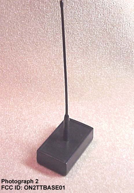
Click to zoom
Application Details
- Equipment Class
- CYY - Communications Receiver used w/Pt 15 Transmitter
- Date of Grant
- Jan 09, 2000
- Application Purpose
- Original Equipment
- Date of Application
- Dec 18, 1999
- Frequency Range
- 418.00000000 - 418.00000000
- Company
- InfoClip
- Country
- United States
Documents & Files
Document Text
Text extracted from the exhibit documents filed with the FCC. Open a document above to read the original.
Users Manual
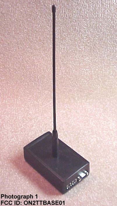
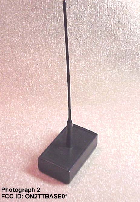
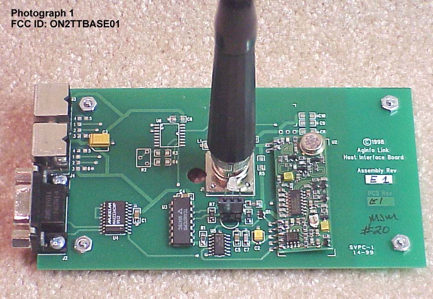
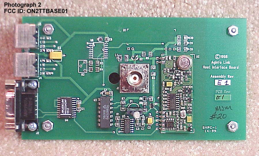
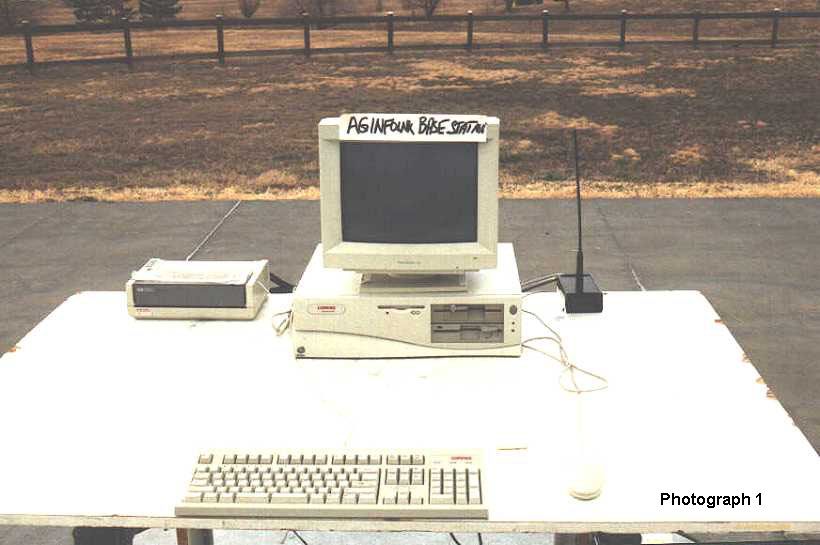
© AgInfoLink Technologies 2 FCC EMISSIONS COMPLIANCE NOTE: This equipment has been tested and found to comply with the limits for a Class B digital device, pursuant to Part 15 of the FCC Rules. These limits are designed to provide reasonable protection against harmful interference in a residential installation. This equipment generates, uses and can radiate radio frequency energy and, if not installed and used in accordance with the instructions, may cause harmful interference to radio communications. However, there is no guarantee that interference will not occur in a particular installation. If this equipment does cause harmful interference to radio or television reception, which can be determined by turning the equipment off and on, the user is encouraged to try to correct the interference by one or more of the following measures: -Reorient or relocate the receiving antenna. -Increase the separation between the equipment and receiver. -Connect the equipment into an outlet on a circuit different from that to which the receiver is connected. -Consult the dealer or experienced radio/TV technicians for help. CAUTION: Changes or modifications not expressly approved or authorized by the manufacturer may violate the compliance of this equipment to the Class B limits for a digital device and could, thereby, void the users authority to operate the equipment. © AgInfoLink Technologies 3 Tag Tracker Wireless RFID ISO Tag Reader Quickstart Instructions (Rev A2 15-11-99) These instructions are intended to guide the user through the basic setup and operation of the AgInfoLink Tag Tracker. Preparing For Use Unpacking The Tag Tracker and its accessories are packaged in one box. The box contents can be identified by the label information attached. Remove all items from the shipping box, and compare the contents with the inventory list provided below. Contents The AgInfoLink Tag Tracker and accessories are provided with the following components. Please contact AgInfoLink Product Support in the event that the shipping box contents are damaged, deficient or defective at 1 (800) 287-8787. Table 1 - Contents of AgInfoLink Tag Tracker and Accessories Component / Item 1 Wireless Tag Tracker RF/ID Wand Reader 1 Tag Tracker Base Station 1 Serial Cable (9-pin) 1 Mouse-port extension cable 1 110-volt 50-60Hz Battery Charger 1 Re-Chargeable Makita 9000 NiCad 9.6 volt Battery 1 Antenna Top The diagram on the next page illustrates the Tag Tracker’s features. © AgInfoLink Technologies 4 Figure 1 Table 2 – Features and Description of Use Feature / Item Description of Use Base station Wireless receiver from reader. Provides data to PC via serial cable. I/R Trigger Activates transponder reading from ON state. Scan LED Indicator LED is Red when searching for a responder. Flashes Yellow if a responder is read. Dual Scan Face Tag can be read with either side of reader. Handle Ambidextrous gripping surface. End Cap Battery Hatch for accessing battery compartment. End Cap Screw Retains End-cap in place. Data Cable Connects Base Station to PC. PS-2 Cable Provides power to Base Station from PC. Plugs into mouse port on PC. Base Station Power Switch/Toggle Handle / Battery Compartment Battery Door To Computer Mouse Port To Computer Serial Port Low Battery Scan LED Indicator Infra-Red To Mouse NONREMOVABLE Antenna Thumb Screw © AgInfoLink Technologies 5 Table 2 – Features and Description of Use ( Continued ) Feature / Item Description of Use Enclosure Rugged, shock and splash resistant enclosure. Low Battery Indicator Provides low-battery warning. Power Switch/Toggle Provides main power to the reader. When switched toward the screw heads, the main power is on. Non-Removable Antenna Receives data from Reader into Host Interface. Setup In order to prepare the Reader for use, the rechargeable Ni-Cad battery must be installed. Since the Ni- Cad battery is shipped in a discharged state, it must be fully charged (Approximately 1 hour using the included charger) prior to Reader use. To minimize battery charge memory, do not recharge the battery until the low battery LED becomes active. Battery Installation Instructions • Unscrew the Battery hatch fastener by turning it counter-clockwise approximately 5 complete turns. The fastener will accept a coin as a screwdriver if needed. • Open hatch by swinging it down away from the Readers handle (See figure 2). Figure 2 • NOTE- Tag Tracker ships with the battery already installed. Battery can only be removed or inserted in one way due to a molded guide-slot. • Powered by 9.6 volt Makita Ni-Cad battery. Battery accessed with a thumb screw hatch. Charged with standard Makita charger . • To insert the charged battery, line up raised rib on the battery with the molded slot in the battery compartment. (See figure 3.) © AgInfoLink Technologies 6 Figure 3 • To secure battery and battery compartment, screw end-cap fastener clock-wise approximately 5 turns until seated. Base Station Setup AgInfoLink’s Tag Tracker is powered through the host computer's mouse port. No battery is required. A second mouse connection is provided on the Base Station to allow continued use of an external mouse. Either of the small circular connectors on the base station can be used for the power or external mouse (interchangeable). The Base Station is cabled to an available port on the host computer, using a straight serial cable (DB9F to DB9M). The baud rate is 1200,with parity, data, and stop bits of N,8,1. • Thread the provided antenna top into the antenna tower on the Host Interface. • Using the provided Serial cable, plug the appropriate end into the 9-pin port (DB9-F) on the Tag Tracker Base Station. (See Figure 4) • The Serial cable will only connect in one way to eliminate confusion. The other end will connect to the serial port (DB9-M) on your PC. Figure 4 Guide Slot Serial Port Cable connects here. © AgInfoLink Technologies 7 • The included PS-2 extension cable provides power to the Host Interface. If you are using…
Text truncated - open the document above for the full version.
Cover Letter(s)
December 19, 1999 Federal Communications Commission Authorization And Evaluation Division 7435 Oakland Mills Road Columbia, MD 21046 Reference: FCC ID: ON2TTBASE01 Gentlemen, This application is being filed for an original grant pursuant to parts 2 and 15, subpart B of the FCC rules for a Receiver operating at 418 MHz. pursuant to PP 15.33, pp 15.107 and pp. 15.109 of Part 15. The transition rule in Section 15.37 does not apply. This device shows compliance under the new rules adopted with Docket 87-389. The enclosure on the unit tested is entirely uncoated plastic. The antenna which will be furnished with the product is as indicated in the Exhibit 3 photographs. This antenna is internal and not accessible to the user and therefore complies with Section 15.203. There are cover letters which request confidentiality and a corporate name and address change. The contact person, phone #, FAX# and email address are the same as before. The application exhibits are organized as follows: Exhibit 1: FCC ID plate and location. Exhibit 2: Responsibility of the Grantee and Statement of Test Accuracy. Exhibit 3: UUT External Photos Exhibit 5: Schematics Exhibit 6: EMI Test Report Exhibit 7: Test Photos Exhibit 8: Users Manual Exhibit 9; Internal Photos Exhibit 13: Cover Letter, Letter of Authorization, Request for Confidentiality, Request for Corporate Name/address Change Thank you for your time and attention to these matters. Sincerely, Mark Lapchak President Phone/FAX: 303/771-6925
Test Report
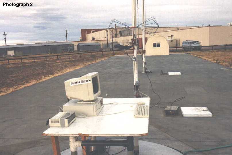
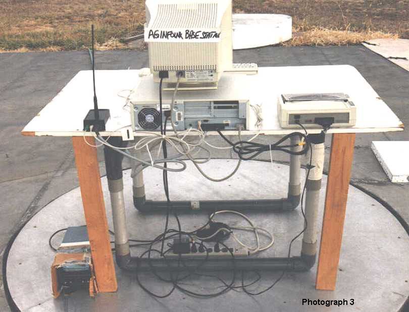
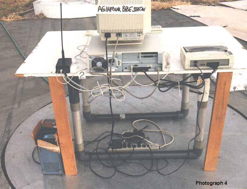
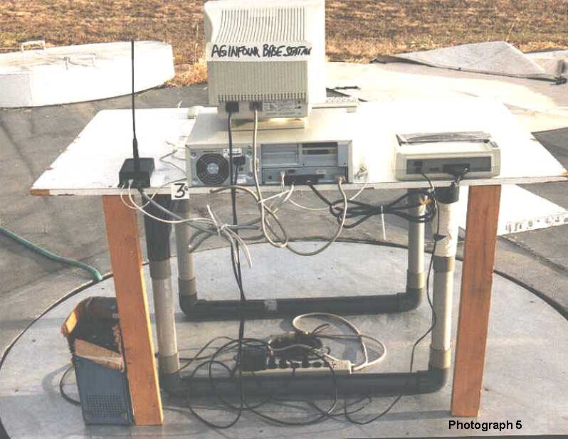
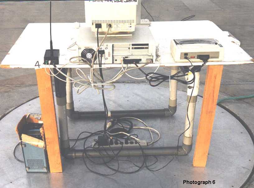
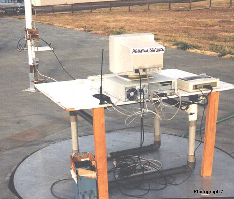
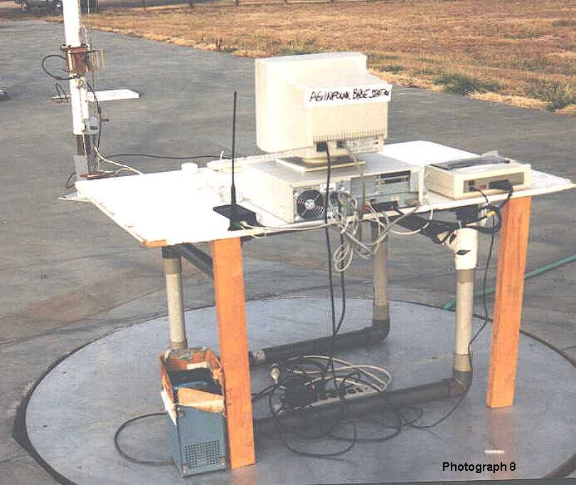
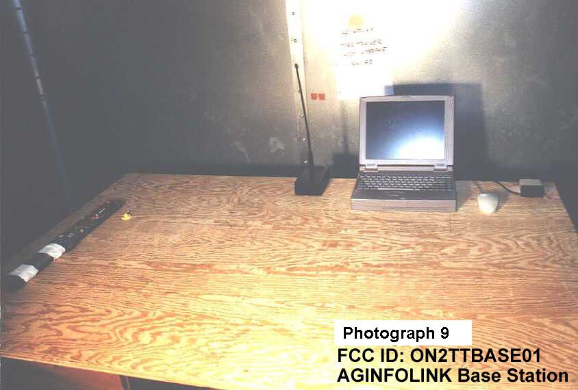
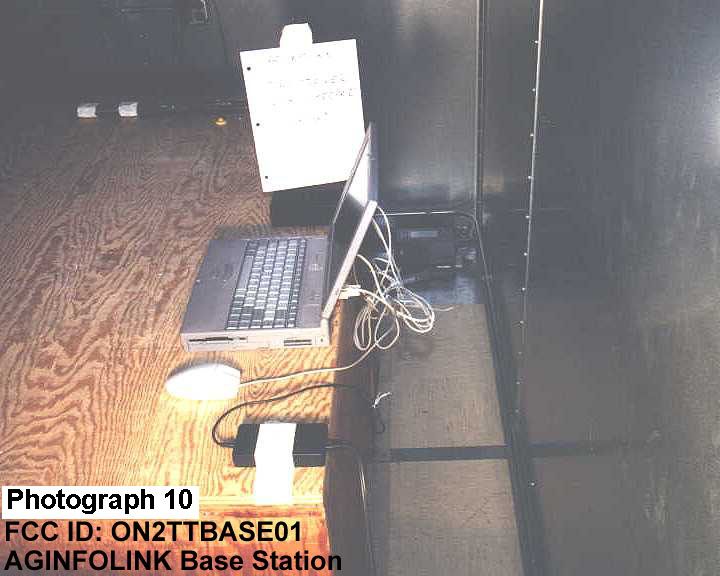
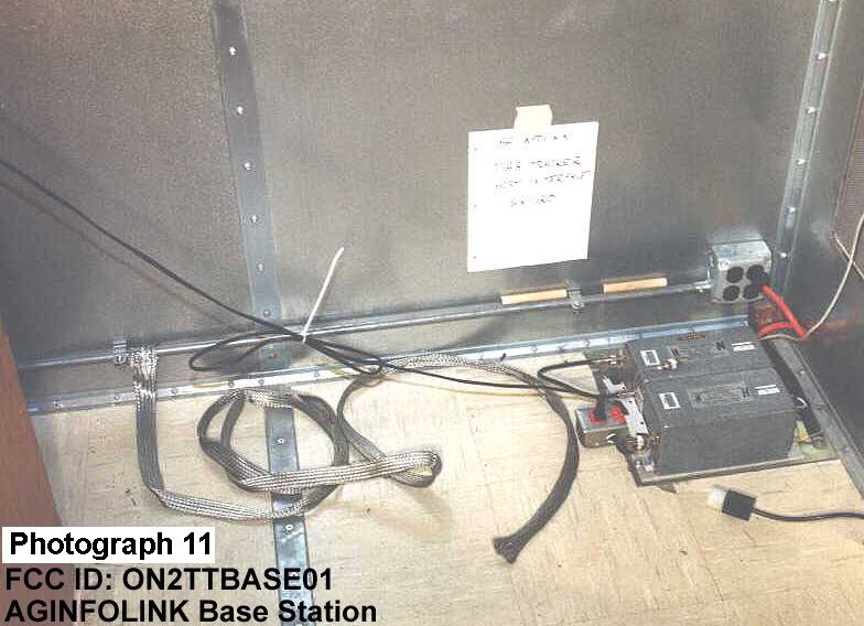
FCC ID: ON2TTBASE01 1 RF ENERGY EMISSION TEST REPORT OF THE AGINFOLINK Inc. Tag Tracker Base Station Receiver PREPARED BY: Markian Lapchak Mark Lapchak & Associates Inc. 6721 S. Leyden Ct. Englewood, Co. 80112 NARTE CERTIFICATION: EMC 001676 PREPARED FOR: AGINFOLINK Inc. 1821 Left Hand Circle Longmont, CO 80501 303/702-1299 12/02/99 aginfo2 FCC ID: ON2TTBASE01 2 TABLE OF CONTENTS SUMMARY 1.0 SCOPE AND OBJECTIVE OF TEST 2.0 UNIT TO BE TESTED 3.0 FACILITY REQUIREMENTS 3.1 SITE ATTENUATION 3.2 INSTRUMENTATION 4.0 SPURIOUS RADIATED EMISSIONS TEST 4.1 PROCEDURE 4.2 RESULTS 5.0 Conducted Emissions 5.1 PROCEDURE 5.2 RESULTS APPENDICES APPENDIX I TABLES1&2 GRAPH5&6 APPENDIX II TABLE OF CORRECTION FACTORS TABLE OF UUT OSCILLATOR FREQUENCIES TEST SETUP BLOCK DIAGRAMS APPENDIX III FIGURES1-4 GRAPHS1-4 THEORY OF OPERATION BASE STATION INTERNAL BLOCK DIAGRAM FCC ID: ON2TTBASE01 3 SUMMARY The testing was performed under the provisions of ANSI C63.4/1992 and the OATS was calibrated in accordance with ANSI C63.4/1992. The AGINFOLINK Host Interface (RECEIVER), is hereafter referred to as the UUT. The UUT, with test setup as described in the block diagrams of Appendix II,PASSESall the radiated requirements, the FCC Part 15, Subpart B, Class B regulations, pp 15.107 and 15.109 governing emissions limits for unintentional radiators.. The maximum electromagnetic field strength at 233.86 MHz was 43 db verses a spec limit of 46 db when measured with a quasi-peak detector at 120 KHz bandwidth. The spurious radiated emissions of the receiver, which came closest to the limit are as follows, rounded to the nearest db: FREQUENCY (MHz) EMISSION LEVEL (dbμv/meter) Polarization MARGIN(db) TABLES Appendix I 167 35 Horizontal -9 1 233.86 43 Horizontal -3 1 601.42 38 Horizontal -8 1 233.86 41 Vertical -5 2 601.42 40 Vertical -6 2 668.15 38 Vertical -8 2 For more details, see Appendix I, Tables1-2andGRAPHS5-6. A negative margin means that the emissions are under the specified limit. All other emissions from Tables 1 - 2, not listed above, were at least 8 db under the applicable limits. The peak power line conducted emissions were at least 10 db under the limit as shown in Appendix III, GRAPHS 1-4. The (receiver)Host Interface antenna in connected internally to the unit enclosure and cannot be substitued by the user. Therefore no direct terminal measurements were required. FCC ID: ON2TTBASE01 4 SUMMARY (cont) INFORMATION SUPPLIED TO THE USER The manual contains a cautionary statement required by Section 15.21 of the FCC rules for an intentional radiator." CAUTION: Changes or modifications not expressly approved or authorized by the manufacturer may violate the compliance of this equipment to the Class B limits for a digital device and could, thereby, void the users authority to operate the equipment. The label on the outside of the equipment enclosure contains the FCC ID and the following text: FCC ID:ON2TTBASE01 This device complies with Part 15 of the FCC Rules. Operation is subject to the following two conditions: (1) this device may not cause harmful interference, and (2) This device must accept any interference received, including interference that may cause undesired operation. AGINFOLINK shall maintain the records listed in Section 2.938 of the FCC rules. FCC ID: ON2TTBASE01 5 1.0 SCOPE AND OBJECTIVE OF TEST To determine the degree of compliance of products to the Federal Communications Commission Part 15 Subpart B requirements for unintentional radiators which limit emissions of Receivers pursuant to pp 15.107 and 15.109 of the Rules through the certification process. 2.0 UNIT TESTED The Host Interface (Receiver), manufactured by AGINFOLINK Inc., 1821 Left Hand Circle, Suite A, Longmont, CO 80501, hereafter referred to as the UUT, is intended to transfer the coding of a passive device ID TAG read by a companion transmitter and transferred to the computer through the serial port. Power is applied to the UUT throught the PS2 mouse port on the PC. The receiver is a direct conversion SAW (Surface Acoustic Wave) device and in and of itself contains no internal clocks or local oscillators. 3.0 FACILITY REQUIREMENTS 3.1 Site Attenuation The radiated testing described herein was accomplished on the METRUM OATS which is located at 4800 E. Dry Creek Road, Littleton, CO 80122. This site meets the requirements of FCC 47 CFR rules, Section 2.948. Refer to FCC File # 31040/SIT/1300F2 for a detailed description of the site. The test area is free of reflecting objects in an area as defined in Figure 1, Appendix III. FCC ID: ON2TTBASE01 6 3.2 Instrumentation Measurements/Radiated: Polarad ESV Receiver, #6003594, calibrated 2/10/99, calibration due 2/10/2000. HP 8565A Spectrum Analyzer, s/n 2210A02349, 100 MHz - 18 GHz, Calibrated 9/27/99, Calibration Due 3/27/2000. Ailtech 94455-1 Biconical Antenna, 30 -200 MHz, Cal'd 8/3/99, Cal Due 8/3/2000. Ailtech 96005 Log Periodic Antenna, 200 MHz - 1 GHz, Cal'd 8/3/99, Cal Due 8/3/2000. AH Systems Horn Antenna, model SAS-200/571, s/n 339, 1- 18 GHz, Calibrated 4/14/99, No re-calibration required. Avantek UTC 10-220-1 25 db Preamp, #211.093, Calibrated 3/8/99, calibration due 3/8/2000. JCA Technology JCA 15-416, 40 db preamp, # 6010088, 1-5 GHz, Calibrated 9/3/99, Calibration Due 9/3/2000. Measurements/Conducted: HP 8568B Spectrum Analyzer, #6003693/94/95, 100 Hz - 1.5 GHz, Calibrated 3/10/99, Calibration Due 3/10/2000. Solar 8028-50-TS-24-BNC UUT LISN, # 6009941/6009942, Calibrated 6/28/99, Calibration Due 6/28/2000. Solar 7930-10 High Pass filter, #6009940, Calibrated 6/28/99, Calibration Due 6/28/2000. HP 7550A Plotter, No Calibration Required. FCC ID: ON2TTBASE01 7 4.0 SPURIOUS RADIATED TEST PROCEDURE AND RESULTS 4.1 Procedure 4.1.1Setup of equipment on the test site, for detailed measurements, was according to Figure 2, Appendix III and the BLOCK DIAGRAM of Appendix II.The ANSI C63.4/1992 measurement procedure was followed. 4.1.2The UUTs was operated during the test as follows: a. A 418 …
Text truncated - open the document above for the full version.
Contact Information
Applicant
Lee Curkendall(Chief Technology Officer)
303-682-9898Fax: 303-265-9897
Test Firm
Sypris Test and MeasurementMarkian Lapchak
Technical Specifications
| # | Rule Parts | Frequency Range | Power Output |
|---|---|---|---|
| 1 | 15B | 418 MHz - 418 MHz | - |
Other Applications from InfoClip
ON2TTREADER02
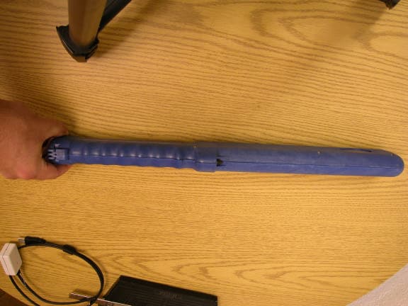
Dec 08, 2004RFID Reader
Equipment Class
DCD - Part 15 Low Power Transmitter Below 1705 kHz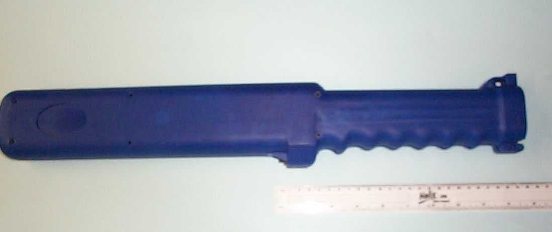
ON2BT3READER01
Nov 10, 2004Wireless RFID Reader
Equipment Class
DCD - Part 15 Low Power Transmitter Below 1705 kHz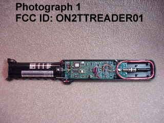
ON2TTREADER01
Feb 09, 2000Tag Reader TX
Equipment Class
DXX - Part 15 Low Power Communication Device Transmitter