ON5CC-CL200-TXWheel Revolution Transmitter
CATEYE Co., Ltd.
Click to zoom
Application Details
- Equipment Class
- DCD - Part 15 Low Power Transmitter Below 1705 kHz
- Date of Grant
- Feb 27, 2000
- Application Purpose
- Original Equipment
- Date of Application
- Dec 02, 1999
- Equipment Note
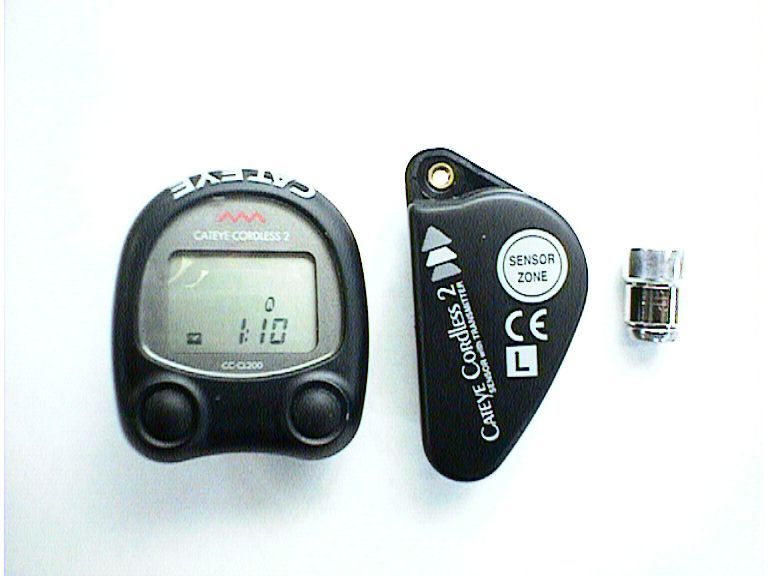
- Wheel Revolution Transmitter
- Frequency Range
- 0.01800000 - 0.01800000
- Company
- CATEYE Co., Ltd.
- Country
- Japan
Documents & Files
Document Text
Text extracted from the exhibit documents filed with the FCC. Open a document above to read the original.
Users Manual
TIRE SIZEL(cm)TIRE SIZEL(cm) 24 x 11753 24 x 3/4 Tubular1785 24 x 1-1/8 Tubular1795 24 x 1-1/41905 24 x 1.751890 24 x 2.001925 24 x 2.1251965 26 x 1(559mm)1913 26 x 1(650c)1952 26 x 1.251953 26 x 1-1/8 Tubular1970 26 x 1-3/82068 26 x 1-1/22100 26 x 1.402005 26 x 1.501985 26 x 1.752030 26 x 1.952050 26 x 2.002055 26 x 2.12068 26 x 2.1252070 26 x 2.352083 27 x 12145 27 x 1-1/82155 27 x 1-1/42161 27 x 1-3/82169 650 x 35A2090 650 x 38A2125 650 x 38B2105 700 x 18C2070 700 x 19C2090 700 x 20C2086 700 x 23C2096 700 x 25C2105 700 x 28C2136 700 x 30C2170 700 x 32C2155 700C Tubular2130 700 x 35C2168 700 x 38C2180 700 x 44C2224 Copyright© Aug. 1994 CAT EYE Co., Ltd. CCMCL2-981118 Printed in Japan 0687303 9 US. PAT. NO.4633216,4636769,4642606,5089775,5236759 & Design Patented. Setting Values Cross Reference Table (The tire size is marked on both sides of the tire.) Specifications Controller ..................................... 4-bit 1-chip Microcomputer (Crystal Controlled Oscillator) Display .......................................... Liquid Crystal Display Sensor .......................................... No Contakt Magnetic Sensor Cordless Système .....................................Directional electromagnetic induction Operating Temperature Range/ .................0°C - 40°C(32°F - 104°F) LIMITED WARRANTY 2-Year Warranty: Only Main Unit/Sensor If trouble occurs during normal use, the part is repaired or replaced free of charge. The service must be performed by CATEYE Co., Ltd.. and the product needs service must be returned to CATEYE Co., Ltd. directly by purchaser. When returning the product for CATEYE warranty service, pack it very carefully, and enclose the warranty certificate and instructions for repair. Please make sure to write or type your name and address clearly on the warranty certificate, so that the product can be shipped back to you as soon as the necessary repair/adjustment is completed. Insurance, handling and transportation charges to our service shall be borne by person desiring service. Address for service CO ., LTD. 2-8-25, Kuwazu, Higashi Sumiyoshi-ku, Osaka 546-0041 Japan Attn.: CATEYE Customer Service Section Service & Research Address for United States Consumers: CATEYE Service & Research Center 1705 14th St. 115 Boulder, CO 80302 Phone: 303-443-4595 Toll Free: 800-5CATEYE Fax: 303-473-0006 e-mail: [email protected] ® CYCLOCOMPUTER Model CC-CL200 L A B AT B AT A COIN SE N S O R Z O N E S E N S O R w i t h T R A N S M I T T E R sensor OPERATION FEATURES Two buttons are provided on the top of the main unit and two on the bottom. These buttons are used as follows: •Mode Button (top left button) Whenever this button is pressed, the mode display changes in the order shown in fig.1, and the data is displayed on the sub-display. Note: If this button is kept pressed for more than 2 seconds, display appears. •Start/Stop Button (top right button) Measurement of trip distance, elapsed time and average speed is started or stopped when the start/stop button is pressed. Whenever this button is pressed, start and stop are repeated. During measurement the speed scale symbol blinks. Note: This button does not function if the auto mode function is set to ON [Refer to the explanation of the Auto (Automatic Start/Stop) Function below]. •Set Button (bottom left button) •To set the wheel circumference: Stop the measurement in the (O) mode, then press the SET button. •To set the 24-hour clock time: Stop the measurement in () mode, then press the SET button. •To set auto mode to ON or OFF: Select the (T),(A) or (D) mode, then press the SET button. •AC (All Clear) Button (bottom right button) When this button is pressed, all the data stored in memory is cleared. After all displays illuminate, the "mile/h" symbol illuminates. This button should be pressed only after replacing the battery or when irregular display of infor- mation occurs due to static electricity,etc. Once this button is pressed and all memory is erased, it will be necessary to set the wheel circumference, time, etc. again. (refer to Main Unit Preparation) Reset Operation: (Fig.2) Press left button to select any mode except total distance (O) and press left and right buttons together. Stored data of trip distance (D), elapsed time (T), average speed (A) and maximum speed (M) are all reset to zero. (In the total distance display mode, the current wheel circumference (A) or (B) is shown.) MAIN UNIT PREPARATION User must make the following setting according to instructions before the cyclocomputer can be used properly. 1. How to measure the exact Wheel Circumference (L)(Fig.3) First, adjust tire pressure and then put a mark on the tire tread and the ground simultaneously. Then ride the bike one full wheel revolution. Mark the ground at the end of one revolution and then measure the distance between the two marks. This measure is your actual wheel circumference. Or, the "Setting Val- ues Cross Reference Table" can help you to find out an approximate wheel circumference according to tire size. 2. Setting the Speed Scale (Fig.4) When the AC button is pressed and all displays illuminate then the "mile/h" appears as shown in fig.4. "km/h" and "mile/h" are displayed alternatively each time the right button is pressed. Select any speed scale as desired and press SET button to complete the setting. 3. Setting the Wheel Circumference (Fig.5.6) This cyclocomputer is able to memorize two different wheel circumferences. One main unit can be used on two bicycles subject to buy another set of bracket and sensor. Two wheel circumferences, (A) 2155mm and (B) 2030mm, have been set be- fore the cyclocomputer left our factory. The (A) wheel circumference 2155mm (standard for 27 inch tire) will blink as shown in fig.5. If you want to enter 2155mm and 2030mm, simply press the SET button. If you want to change, press either the right button to increase or left button to decrease the number. To change the number rapidly keep the button pressed. Once you re…
Text truncated - open the document above for the full version.
Cover Letter(s)
Feb 14, 2000 To: To whom it may concern Equipment Authorization Branch Subject: Electronic Submission for FCC ID: ON5CC-CL200-TX Form 731 confirmation No. : EA96151 Would you please tell us current certification application status for the following FCC ID and FCC Form 731 confirmation number. FCC ID: ON5CC-CL200-TX Form 731 confirmation No. : EA96151 We should appreciate your reply. Best regards, Kosei Shibata EMC Div. Japan Quality Assurance Organization Kita-Kansai Testing Center E-mail: [email protected]
Operational Description
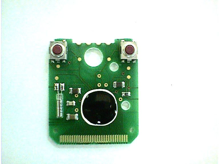
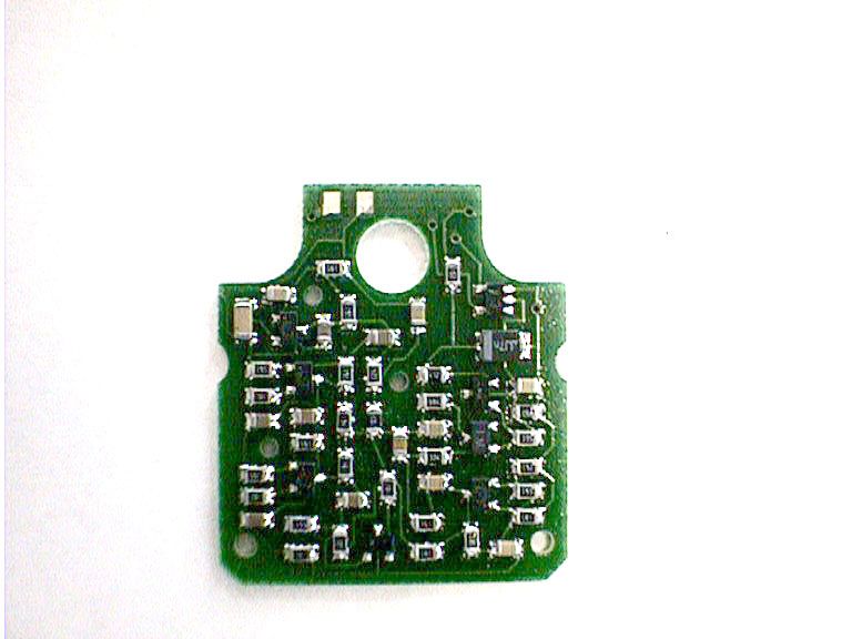
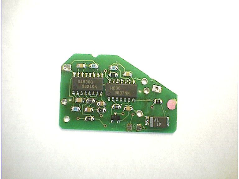
Operation of CC-CL200 A) Sensor(Transmitter) a. Reed swith Reed switch generates one signal per every rotation of the wheel. b. Pulse generator One shot pulse with 3msec pulse width is generated by reed switch signal. c. Oscillator Oscillator generates pulses continuously during the one shot pulse. d. Amplifier The pulses are amplified and fed to transmitter coil. e. Transmitter coil Transmitter coil emits electromagnetic wave of 18kHz during the 3msec. B) Main unit(Receiver) a. Receiver coil Main unit detects 18kHz electromagnetic wave at receiver coil. b. RF amplifier and pulse shaper As the received signal strength is very low, the signal is amplified and shaped. c. CPU controller The received pulses are counted and the pulse intervals are measured. Then, the travelling speed, distance and other functions are displayed. • Block diagram A) Sensor (Transmitter) B) Main unit (Receiver) Transmitter coil AmplifierOseillator Reed switch Receiver coilRF amplifier Pulse shaper (digitizer) Crystal oscillator Display (LCD panel) CPU controller Pulse generator Speed sensor Push button
Test Report
Issue Date : October 19, 1999 Page 1 of 14 EMC EMISSION - TEST REPORT JQA APPLICATION No.: KL8090454 Name of Product: CYCLOCOMPUTER(CATEYE CORDLESS 2) Model/Type No.: CC-CL200 FCC ID: ON5CC-CL200-TX Applicant : CATEYE CO., LTD. Address : 2-8-25, Kuwazu, Higashi-Sumiyoshi-Ku, Osaka, Japan Manufacturer : CATEYE CO., LTD. Address : 2-8-25, Kuwazu, Higashi-Sumiyoshi-Ku, Osaka, Japan Final Judgement :Passed TEST RESULTS IN THIS REPORT are obtained in use of equipment that is traceable to Electro- technical Lab. of MITI Japan and Communications Research Lab. of PTT Japan. THE TEST RESULTS only responds to the test sample. This test report shall not be reproduced except in full. JAPAN QUALITY ASSURANCE ORGANIZATION (JQA) KITA-KANSAI TESTING CENTER EMC DIVISION LAB CODE: 200191-0 Page 2 of 14 DIRECTORY Page A) Documentation Directory2 Test Regulation / General Information3 Test Conditions4-5 Configuration of EUT / Operation mode of the EUT6 - 7 EUT Modification / Responsible Party8 Test results / Measurement Uncertainty9 Summary10 Test System-Arrangement (Drawings) 11 Preliminary Test and Test-setup (Drawings) 12 Test-setup (Photographs) at worst case 13 B) Test data Conducted Emission450 kHz - 30 MHzN/A Electromagnetic Field Radiated Emission9 kHz - 180 kHz14 JQA Application No. : KL8090454Regulation : CFR 47 FCC Rules Part 15 Model No.: CC-CL200Issue Date : October 19, 1999 FCC ID: ON5CC-CL200-TX JQA Application No. : KL8090454Regulation : CFR 47 FCC Rules Part 15 Model No.: CC-CL200Issue Date : October 19, 1999 FCC ID: ON5CC-CL200-TX Page 3 of 14 TEST REGULATION FCC Rules and Regulations Part 15 Subpart A and C (April 16, 1999) ô- Class A Digital Device ô- Class B Digital Device ò- Intentional Radiator Test procedure: Radiated emission test was performed according to the procedures in ANSI C63.4-1992. GENERAL INFORMATION Test facility: 1) Test Facility located at Kita-Kansai : 1st and 2nd Open Sites (3 m Site) Test Facility located at Kameoka Open Site (3, 10 and 30 m, on common plane) FCC filing No. : 31040/SIT 1300F2 2) KITA-KANSAI TESTING CENTER is recognized under the National Voluntary Laboratory Accreditation Program for satisfactory compliance established in Title 15, Part 285 Code of Federal Regulations. NVLAP Lab Code: 200191-0 Description of the Equipment Under Test (EUT): 1) Name: CYCLOCOMPUTER(CATEYE CORDLESS 2) 2) Model/Type No.: CC-CL200 3) Product Type: Mass-Production (S/N: A433152) 4) Category: Intentional Radiator 5) EUT Authorization: - Verification- Certification- D.o.C.ôòô 6) Transmitting frequency: 18 kHz 7) Power Rating: DC 3V (Lithium Battery CR2032x1) Definitions for symbols used in this test report: ò- Black box indicates that the listed condition, standard or equipment is applicable for this Report. ô- Blank box indicates that the listed condition, standard or equipment is not applicable for this Report. JQA Application No. : KL8090454Regulation : CFR 47 FCC Rules Part 15 Model No.: CC-CL200Issue Date : October 19, 1999 FCC ID: ON5CC-CL200-TX Page 4 of 14 TEST CONDITIONS AC Powerline Conducted Emission Measurement wasperformedinthefollowingtestsite. Test location: KITA-KANSAI Testing Center 7-7, Ishimaru, 1-Chome, Mino-Shi, Osaka, 562-0027, Japan ô-Shieldedroom KAMEOKA EMC Branch 9-1, Ozaki, Inukanno, Nishibetsuin-Cho, Kameoka-Shi, Kyoto, 621-0126, Japan ô-Shieldedroom ô- On metal plane of open site Used test instruments and sites: Model No.Device IDast Cal. DateCal. Interval L ô-ESH3A-1 ô-ESH2A-2 ô-ESH2A-3 ô-KNW-407D-6 ô- KNW-408D - 11 ô-KNW-242D-7 ô- ESH3-Z5D - 12 ô- KNW-341CD - 13 ô- KNW-408D - 14 ô- KNW-244CD - 77 ô- KNW-408D - 78 ô- ESH2-Z5D - 10 ô- ESH2-Z3D - 17 ô- 8568BA - 10 ô- 8566BA - 13 ô- 8593AA - 15 ô-CableH-7 ô-CableH-8 Environmental conditions: Temperature:∞C Humidity:% JQA Application No. : KL8090454Regulation : CFR 47 FCC Rules Part 15 Model No.: CC-CL200Issue Date : October 19, 1999 FCC ID: ON5CC-CL200-TX Page 5 of 14 Magnetic Field Radiated Emission Measurement was performed in the frequency range of 9 kHz - 30 MHz, in the following test site. Test location: KITA-KANSAI Testing Center 7-7, Ishimaru, 1-Chome, Mino-Shi, Osaka, 562-0027, Japan ô- 1st site (3 meters) ò- 2nd site (3 meters) KAMEOKA EMC Branch 9-1, Ozaki, Inukanno, Nishibetsuin-Cho, Kameoka-Shi, Kyoto, 621-0126, Japan ô- 3 meters ô- 10 meters ô- 30 meters Used test instruments: Model No.Device IDast Cal. DateCal. Interval L ô-ESH3A-1 ò- ESH 2A - 2May, 19991 Year ô-ESH2A-3 ò- HFH2-Z2C - 2February, 19991 Year ô- HFH2-Z2C - 3 Environmental conditions: Temperature: 20 ∞C Humidity: 50 % JQA Application No. : KL8090454Regulation : CFR 47 FCC Rules Part 15 Model No.: CC-CL200Issue Date : October 19, 1999 FCC ID: ON5CC-CL200-TX Page 6 of 14 CONFIGURATION OF EUT The Equipment Under Test (EUT) consists of: DescriptionApplicantModel No.FCC ID (Manufacturer)(Serial No.) CYCLOCOMPUTERCATEYE CO., LTD.CC-CL200ON5CC-CL200-TX (CATEYE(CATEYE CO., LTD.)(A433152) CORDLESS 2 ) The measurement was carried out with the following equipment connected: DescriptionGrantee/DistributorModel No.FCC ID (Serial No.) WheelCATEYE CO., LTD.--N/A Speed Simulator(--) Type of Interference Cable(s) and the AC Power Cord used with the EUT: No.CableShielded Ferrite Core Length None JQA Application No. : KL8090454Regulation : CFR 47 FCC Rules Part 15 Model No.: CC-CL200Issue Date : October 19, 1999 FCC ID: ON5CC-CL200-TX Page 7 of 14 Operation - mode of the EUT: The EUT is transmitting the signal of wheel rotation. Test system: The EUT is a wheel rotation sensor(rotation sensor and transmitter), a part of cordless cyclometer. The EUT was connected to the wheel speed simulator for the simulation of the wheel rotation. Special accessories: None The used (generated) frequencies in the EUT: Transmitting frequency : 18.0 kHz JQA Application No. : KL8090454Regulation : CFR 47 FCC Rules Part 15 Model No.: CC-CL200Issue Date : October 19, 1999 FCC ID: ON5CC-CL200-TX Page 8 of 14 EUT Modification ò- No modifications were conducted by JQ…
Text truncated - open the document above for the full version.
Contact Information
Applicant
Koichi Tsuyama(President)
Technical Contact
Japan Quality Assurance Org.Kosei Shibata
[email protected]81-727-29-2246
7-7, Ishimaru, 1-Chome · Osaka · Japan
Non-Technical Contact
Japan Quality Assurance Org.Makoto Okada
[email protected]81-727-29-2246
Test Firm
Japan Quality Assurance Org.Katsumi Nishii
Technical Specifications
| # | Rule Parts | Frequency Range | Power Output |
|---|---|---|---|
| 1 | 15C | 0.018 MHz - 0.018 MHz | - |
Other Applications from CATEYE Co., Ltd.

ON5-CCGPS100
Nov 09, 2022Air GPS with Bluetooth
Equipment Class
DTS - Digital Transmission System
ON5-HLNW100
Jul 21, 2020Sync Core
Equipment Class
DTS - Digital Transmission System
ON5-TLNW100K
Jul 20, 2020Sync Kinetic
Equipment Class
DTS - Digital Transmission System
ON5-SLNW100
Jul 20, 2020Sync Wearable
Equipment Class
DTS - Digital Transmission System
ON5-SPD30CDC30
May 13, 2020Magnet-less Speed & Cadence Sensors
Equipment Class
DTS - Digital Transmission System