ON5HRSENSORCHeart Rate Chest Strap
CATEYE Co., Ltd.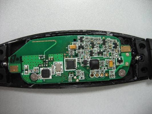
Click to zoom
Application Details
- Equipment Class
- DXX - Part 15 Low Power Communication Device Transmitter
- Date of Grant
- Sep 11, 2007
- Application Purpose
- Original Equipment
- Date of Application
- Sep 10, 2007
- Equipment Note
- Heart Rate Chest Strap
- Frequency Range
- 2410.00000000 - 2473.00000000
- Company
- CATEYE Co., Ltd.
- Country
- Japan
Documents & Files
Document Text
Text extracted from the exhibit documents filed with the FCC. Open a document above to read the original.
Users Manual
ENG-1 ENG Introduction Thank you for purchasing the CATEYE V2c. The V2c is a high-performance computer for riders who wish to train extensively and analyze their data. 2.4GHz-frequency digital wireless technology, which is the same technology used for wireless LAN, is used for both the speed/cadence integrated speed sensor. This technol- ogy practically eliminates interference from external noise and cross-talk with other wire- less computer users, providing you with stress-free riding. Read this instruction manual thoroughly and understand the functions of the product before using it. Keep it in a safe place for future reference. About the manuals Basic installation and operation Please go here for installation of the unit on the bicycle, preparing the computer, and the basic operation of the product. 1. How to install the unit on your bicycle ............... See page 6-8 2. Preparing the computer ..................................... See page 9-14 3. Basic operation of the computer ........................ See page 15-16 Measurement screen Please go here to learn how to operate the computer functions. • Measurement screen .......................................... See page 17-21 Ride data review Please go here to check and manage recorded data • File view ............................................................. See page 23-26 Changing computer configuration Please go here for changing and checking each menu items. • Changing the computer configuration ................ See page 22-33 Advanced use • Recording lap and split time data ....................... See page 19 “Lap function” • Training with target cadence zone ...................... See page 34 “Use of the target zone” Important • Always follow the sections that are marked with “ Warning!!!”. • No part of this manual may be reproduced or transmitted without the prior written permission of CatEye Co., Ltd. • The contents and illustrations in this manual are subject to change without notice. • If you have any questions or concerns about this manual, please contact CatEye at www.cateye.com. ENG-2 Contents Introduction .......................................... 1 About the manuals ............................... 1 Proper use of the CatEye V2c ............... 3 Description of computer and its parts.... 4 Computer ......................................... 4 Accessories ...................................... 4 Screen display ...................................... 5 How to install the unit on your bicycle..... 6 1. Attach the bracket to the stem or handlebar ..................................... 6 2. Mount the speed sensor and magnet ......................................... 7 3. Remove/Install the computer ....... 8 Preparing the computer ........................ 9 Removing the insulation sheet ......... 9 1. Formatting/Restarting operation.... 10 2. Date/Clock setting ...................... 11 3. Tire circumference input ............. 12 4. Set the sensor ID ........................ 13 5. Selecting speed unit ................... 14 6. Operation test ............................. 14 Sensor signal status ....................... 14 Basic operation of the computer ........ 15 Functions on the measurement screen ............................................ 15 Starting/Stopping the measurement ................................. 16 Backlight ........................................ 16 Resetting the measurement data .... 16 Power-saving function .................... 16 Measurement screen .......................... 17 Upper and middle display data ....... 17 Lower display data ......................... 18 Pace function ................................. 19 Lap function ................................... 19 Countdown distance ....................... 20 Target cadence zone ....................... 21 Changing the computer configuration ...................................... 22 File view (FILE VIEW) ..................... 23 Setting the clock/date (CLOCK.DATE) ............................... 27 Wheel selection and tire circumference (WHEEL) ................. 28 Searching the sensor ID (SEnSOR-ID) .................................. 28 Setting the measurement unit (UnIT) ............................................. 30 Total distance manual entry (ODO InPUT) .................................. 30 Setting the auto-mode (AUTO MODE) ................................ 31 Setting the countdown distance (C.D.DST AA AA A) .................................. 31 Setting sound (SOUnD) .................. 32 Setting the target cadence zone (CDC.ZOnE) .................................... 33 Use of the target zone ........................ 34 Trouble shooting ................................ 35 Trouble on display .......................... 35 Trouble on operation ...................... 36 Replacing battery ............................... 37 Computer ....................................... 37 Speed sensor ................................. 37 Maintenance ....................................... 38 Spare accessories .............................. 38 Specifications ..................................... 39 Registration ........................................ 40 Limited warranty ................................ 40 ENG-3 ENG Proper use of the CatEye V2c Observe the following instructions for safe usage. The meaning of icons in this manual: Warning!!! :Sections marked with these icons are critical for safe use of the device. Be sure to follow these instructions. Caution:Important cautionary notes on the use and operation of the V2c. * Helpful tips are highlighted with asteriks. Warning!!! : • Do not concentrate on the data while riding. Always be sure to ride safely. • Do not leave any battery within the reach of children, and dispose of them correctly. If a battery is swallowed, consult a doctor immediately. Caution: • Regularly check the positions of the magnets and the speed/cadence sensors and make sure that they are securely mounted. Tighten it firmly if there is any l…
Text truncated - open the document above for the full version.
Users Manual
ENG-1 ENG Introduction Thank you for purchasing the CATEYE V3. The V3 is a high-performance computer for riders who wish to train extensively and analyze their data. 2.4GHz-frequency digital wireless technology, which is the same technology used for wireless LAN, is used for both the speed/cadence integrated speed sensor and the heart rate sensor. This technology practically eliminates interference from external noise and cross-talk with other wireless computer users, providing you with stress-free riding. Read this instruction manual thoroughly and understand the functions of the computer before using it. Keep it in a safe place for future reference. About the manuals Basic installation and operation Please go here for installation of the unit on the bicycle, use of the heart rate measure- ment function, preparing the computer, and the basic operation of the product. 1. How to install the unit on your bicycle ............... See page 6-8 2. Heart rate sensor ............................................... See page 9 3. Preparing the computer ..................................... See page 10-15 4. Basic operation of the computer ........................ See page 16-17 Measurement screen Please go here to learn how to operate the computer functions. • Measurement screen .......................................... See page 18-22 Ride data review Please go here to check and manage recorded data. • File view ............................................................. See page 24-27 Changing computer configuration Please go here for changing and checking each menu items. • Changing the computer configuration ................ See page 23-34 Advanced use • Recording lap and split time data ....................... See page 20 “Lap function” • Training with target heart rate zones .................. See page 37 “Use of the target zone” Important • Always follow the sections that are marked with “ Warning!!!”. • No part of this manual may be reproduced or transmitted without the prior written permission of CatEye Co., Ltd. • The contents and illustrations in this manual are subject to change without notice. • If you have any questions or concerns about this manual, please contact CatEye at www.cateye.com. ENG-2 Contents Introduction .......................................... 1 About the manuals ............................... 1 Proper use of the CatEye V3 ................. 3 Description of computer and its parts.... 4 Computer ......................................... 4 Accessories ...................................... 4 Screen display ...................................... 5 How to install the unit on your bicycle ... 6 1. Attach the bracket to the stem or handlebar ..................................... 6 2. Mount the speed sensor and magnet ......................................... 7 3. Remove/Install the computer ....... 8 Heart rate sensor .................................. 9 Before wearing the heart rate sensor.... 9 Wearing the heart rate sensor .......... 9 Preparing the computer ...................... 10 Removing the insulation sheet ....... 10 1. Formatting/Restarting operation.... 11 2. Date/Clock setting ...................... 11 3. Tire circumference input ............. 12 4. Set the sensor ID ........................ 13 5. Selecting speed unit ................... 14 6. Operation test ............................. 15 Sensor signal status ....................... 15 Basic operation of the computer ........ 16 Functions on the measurement screen ............................................ 16 Starting/Stopping the measurement ................................. 17 Backlight ........................................ 17 Resetting the measurement data .... 17 Power-saving function .................... 17 Measurement screen .......................... 18 Upper and middle display data ....... 18 Lower display data ......................... 19 Pace function ................................. 20 Lap function ................................... 20 Countdown distance ....................... 21 Target heart rate zone ..................... 22 Changing the computer configuration ... 23 File view (FILE VIEW) ..................... 24 Setting the clock/date (CLOCK.DATE) ................................ 28 Wheel selection and tire circumference (WHEEL) ................. 29 Searching the sensor ID (SEnSOR-ID) ................................... 29 Setting the measurement unit (UnIT) ............................................. 31 Total distance manual entry (ODO InPUT) .................................. 31 Setting the auto-mode (AUTO MODE) ................................. 32 Setting the countdown distance (C.D.DST AA AA A) .................................. 32 Setting sound (SOUnD) .................. 33 Setting the target heart rate zone (HR.ZOnE) ...................................... 34 Heart rate training .............................. 35 1. Improving general fitness ........... 35 2. Training for competition ............. 36 3. Use of the target zone ................ 37 Trouble shooting ................................ 38 Trouble on display .......................... 38 Trouble on operation ...................... 40 Replacing battery ............................... 41 Computer ....................................... 41 Heart rate sensor ............................ 41 Speed sensor ................................. 41 Maintenance ....................................... 42 Spare accessories .............................. 42 Specifications ..................................... 43 Registration ........................................ 44 Limited warranty ................................ 44 ENG-3 ENG Proper use of the CatEye V3 Observe the following instructions for safe usage. The meaning of icons in this manual: Warning!!! :Sections marked with these icons are critical for safe use of the device. Be sure to follow these instructions. Caution :Important cautionary notes on the use and operation of the V3. *…
Text truncated - open the document above for the full version.
Cover Letter(s)
American Telecommunications Certification Body Inc. 6731 Whittier Ave, McLean, VA 22101 September 7, 2007 RE: FCC ID: ON5HRSENSORC_ATCB005366 Attention: Stephen Guo I have a few comments on this Application. Please note that further comments may arise in response to answers provided to the questions below. 1. Please note that N/A is not acceptable for radiated emissions testing. Please note that even if the radiated spurious emissions are greater than 20dB below the limits the FCC and ANSI C63.4 section 10.1.8.2 has stated that you must still report at least 6 readings for a part 15 device even if these are noise floor readings at the harmonics of the fundamental. Please provide a corrected test report in line with the requirements of ANSI C63.4 and the FCC showing at least 6 readings for radiated spurious emissions. 2. In regards to item 1 above, please also include the radiated emissions 6 highest readings in the IC report. 3. Please note that it is not clear from the FCC ID label photo where exactly the FCC ID is to be placed. Please show where this is in relation to the device as a whole. Please also note that the FCC ID label CANNOT be on a removable part of the device. 4. Please clearly show where in the manual the non modification and 2-condition statement required by the FCC are located. Dennis Ward mailto:[email protected] The items indicated above must be submitted before processing can continue on the above referenced application. Failure to provide the requested information may result in application termination. Correspondence should be considered part of the permanent submission and may be viewed from the Internet after a Grant of Equipment Authorization is issued. Please do not respond to this correspondence using the email reply button. In order for your response to be processed expeditiously, you must submit your documents through the AmericanTCB.com website. Also, please note that partial responses increase processing time and should not be submitted. Any questions about the content of this correspondence should be directed to the sender.
Cover Letter(s)
The modified FCC test report has been uploaded to website. The modified IC test report has been uploaded to website. The ID is to be placed in the middle of rear side of strap. It is not a removable part. The modified label location has been uploaded to website. Please refer to the page 2 of the <<User Manual-V2C-2>>
ID Label/Location Info
Statement in user manual:
Test Report
Report No.: GLEMR070300502RFT-1 Page: 1 of 16 FCC ID: ON5HRSENSORC Authorized Signature: Stephen Guo Manager This report refers to the General Conditions for Inspection and Testing Services, printed overleaf This report details the results of the testing carried out on one sample. The results contained in this test report do not relate to other samples of the same product. The manufacturer should ensure that all products in series production are in conformity with the product sample detailed in this report. This report may only be reproduced and distributed in full. If the product in this report is used in any configuration other than that detailed in the report, the manufacturer must ensure the new system complies with all relevant standards. Any mention of SGS International Electrical Approvals or testing done by SGS International Electrical Approvals in connection with, distribution or use of the product described in this report must be approved by SGS International Electrical Approvals in writing. Member of the SGS Group (Société Générale de Surveillance) SGS-CSTC Standards Technical Services Ltd. No.198 Kezhu Road, Science Town Economic& Technology Development District Guangzhou, China 510663Telephone: Telephone: +86 (0) 20 82155555 Fax: +86 (0) 20 82075059 Email: [email protected] FEDERAL COMMUNICATIONS COMMISSION Registration number: 282399 TEST REPORT Application No. : GLEMR070300502RF Applicant: CATEYE Co.,Ltd. FCC ID: ON5HRSENSORC Frequency Band 2.410GHz and 2.473GHz Equipment Under Test (EUT): Name: HEART RATE CHEST STRAP Model No.: HR SENSOR C Standards: FCC PART 15: 2006 Please refer to section 2 for further details. Date of Receipt: 15 May 2007 Date of Test: 15 to 22 May 2007 Date of Issue: 24 May 2007 Test Result : PASS * In the configuration tested, the EUT complied with the standards specified above. SGS-CSTC Standards Technical Services Ltd. Report No.: GLEMR070300502RFT-1 Page: 2 of 16 FCC ID: ON5HRSENSORC 2 Test Summary Test Test RequirementStanadard Paragraph Result Flied Strength of Fundamental FCC PART 15 :2006 Section 15.249 (a) PASS Flied Strength of Unwanted Emissions FCC PART 15 :2006 Section 15.249 (a) Section 15.249 (d) PASS Occupied Bandwidth FCC PART 15 :2006 Section 15.249 PASS Band Edges FCC PART 15 :2006 Section 15.249 (d) PASS Remark: The HEART RATE CHEST STRAP, Model No. HR SENSOR C is a Tx of the set product. The SPEED CADENCE COMBO, Model No. SPD SENSOR C is a Tx of the set product. The BIKE COMPUTER, Model No. V3 and V2c are Rx of the set product. Tx: In this whole report Tx (or tx) means Transmitter. Rx: In this whole report Rx (or rx) means Receiver. SGS-CSTC Standards Technical Services Ltd. Report No.: GLEMR070300502RFT-1 Page: 3 of 16 FCC ID: ON5HRSENSORC 3 Contents Page 1 COVER PAGE ...........................................................................................................................................1 2 TEST SUMMARY ....................................................................................................................................... 2 3 CONTENTS ................................................................................................................................................ 3 4 GENERAL INFORMATION........................................................................................................................ 4 4.1 CLIENT INFORMATION........................................................................................................................... 4 4.2 GENERAL DESCRIPTION OF E.U.T. ........................................................................................................ 4 4.3 DESCRIPTION OF EUT OPERATION........................................................................................................ 4 4.4 STANDARDS APPLICABLE FOR TESTING................................................................................................. 4 4.5 TEST LOCATION.................................................................................................................................... 4 4.6 OTHER INFORMATION REQUESTED BY THE CUSTOMER........................................................................... 4 4.7 TEST FACILITY...................................................................................................................................... 5 5 TEST RESULTS ......................................................................................................................................... 6 5.1 TEST INSTRUMENTS.............................................................................................................................. 6 5.2 E.U.T. OPERATION...............................................................................................................................7 5.3 TEST PROCEDURE & MEASUREMENT DATA............................................................................................ 8 5.3.1 Radiated Emissions ....................................................................................................................... 8 5.3.2 Occupied Bandwidth & Band Edge ........................................................................................12-16 SGS-CSTC Standards Technical Services Ltd. Report No.: GLEMR070300502RFT-1 Page: 4 of 16 FCC ID: ON5HRSENSORC 4 General Information 4.1 Client Information Applicant Name: CATEYE Co.,Ltd. Applicant Address: 2-8-25 Kuwazu,Higashi-Sumiyoshi-ku,Osaka Japan 4.2 General Description of E.U.T. Product Name: HEART RATE CHEST STRAP Model: HR SENSOR C Power Supply: 3.0V DC (1x”CR2032” cell battery) Power Cord: N/A Emission Designation: F9D 4.3 Description of EUT operation The EUT was a set of equipment: The HEART RATE CHEST STRAP, Model No. HR SENSOR C is a Tx of the set product. The SPEED CADENCE COMBO, Model No. SPD SENSOR C is a Tx of the set product. The BIKE COMPUTER, Model No. V3 and V2c are Rx of the set product. The Tx have 2 frequencies between 2.…
Text truncated - open the document above for the full version.
Contact Information
Applicant
Koichi Tsuyama(President)
Test Firm
SGS-CSTC Standards Technical Services Co., LtdJerry Chan
Technical Specifications
| # | Rule Parts | Frequency Range | Power Output |
|---|---|---|---|
| 1 | 15C | 2.41 GHz - 2.47 GHz | - |
Other Applications from CATEYE Co., Ltd.

ON5-CCGPS100
Nov 09, 2022Air GPS with Bluetooth
Equipment Class
DTS - Digital Transmission System
ON5-HLNW100
Jul 21, 2020Sync Core
Equipment Class
DTS - Digital Transmission System
ON5-TLNW100K
Jul 20, 2020Sync Kinetic
Equipment Class
DTS - Digital Transmission System
ON5-SLNW100
Jul 20, 2020Sync Wearable
Equipment Class
DTS - Digital Transmission System
ON5-SPD30CDC30
May 13, 2020Magnet-less Speed & Cadence Sensors
Equipment Class
DTS - Digital Transmission System