ON7DS815900 MHz DSS Cordless Telephone
HC Telecom Co Ltd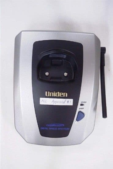
Click to zoom
Application Details
- Equipment Class
- DSS - Part 15 Spread Spectrum Transmitter
- Date of Grant
- Oct 28, 2001
- Application Purpose
- Original Equipment
- Date of Application
- Oct 28, 2001
- Equipment Note
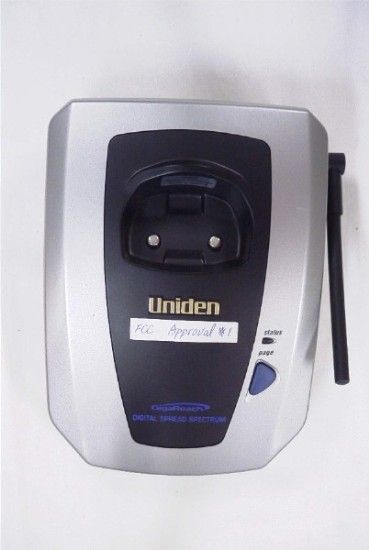
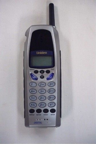
- 900 MHz DSS Cordless Telephone
- Frequency Range
- 902.00000000 - 928.00000000
- Company
- HC Telecom Co Ltd
- Country
- South Korea
Documents & Files
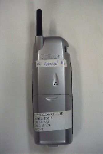
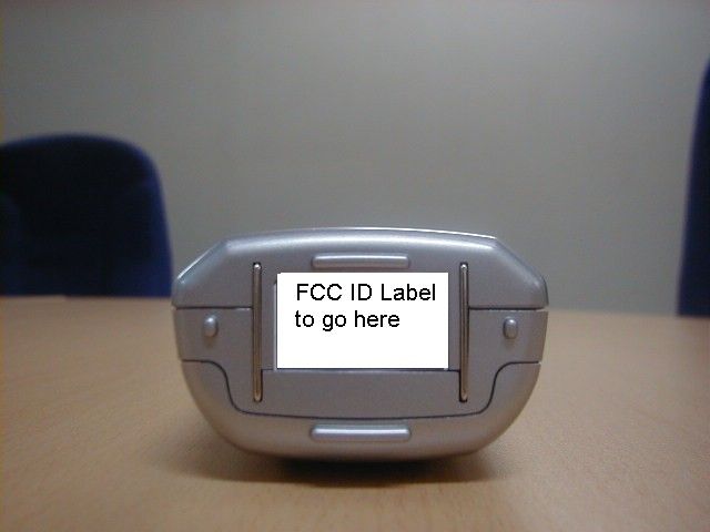

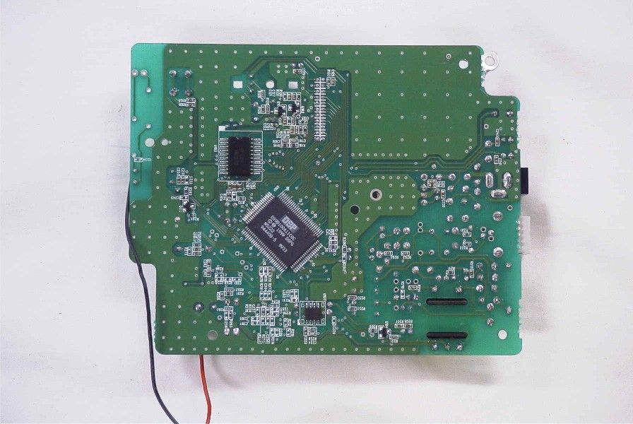
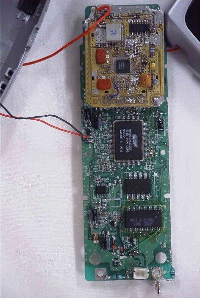
Document Text
Text extracted from the exhibit documents filed with the FCC. Open a document above to read the original.
Users Manual
1 / 16 Contents Features Getting Started Step 1: Checking the packing contents Step 2: Setting up the Base Unit Step 3: Preparing the battery pack Registration Options Adjusting the ringer and earpiece volume Basics Making a Call Call transfer Receiving a Call Redialing a Call Traveling out-of-range Key lock/unlock Telephone Features Memory dialing Storing phone numbers and names Making calls with memory dialing Chain dialing Editing a stored name and/or phone number Erasing a stored name and phone number Paging Handset to Handset communication Caller ID Features Caller ID When the telephone rings Viewing the Caller ID Message list Name tagging Deleting information from the Caller ID list Using the Caller ID list Additional Information Belt clip installation Headset installation Note on power sources Maintenance 2 / 16 Features . 900MHz Digital Spread Spectrum Technology . Multi-Handset operation . Call ID Function . 60 Number Caller ID Memories . Lighted Keypad . 3-Line, 16 Character Backlit Handset Display . 29 Enhanced Memory Dial Locations . 32 Digit Redial . 3 Redial Memories . Flash . Pause . 10 Days Standby Battery Life . 4.5 Hours Talk Time . Handset Earpiece and Ringer Volume Control . Hearing Aid Compatible 3 / 16 Checking the Package Contents Make sure you have received the following items in the package. l Base unit l Handset l Rechargeable battery l AC/DC adapter l Belt clip l Telephone line cord and plug l Owner’s manual Setting up the Base Unit Do the following steps. l Choose the best location l Connect the base unit Choose the best location l After installing the battery pack in the handset, charge your handset at least 12 hours before using the phone. Once the handset battery pack is fully charged, connect the telephone line cord to the base and telephone wall outlet. l The location should be close to both a phone jack and a continuous power outlet, which is not switchable. l Keep the base and handset away from sources of electrical noise such as motors and fluorescent lighting. l Be sure there is sufficient space to raise the base antenna to a vertical position. Connect the base unit 1. Connect the telephone line cord to the TEL LINE jack and to a telephone outlet. 2. Connect the AC adapter to the DC IN 9V jack and to a standard 240V AC wall outlet. 3. Set the base unit on a desk or tabletop and place the handset on the base unit as shown. Then raise the antenna to a vertical position. Note Use only the supplied ??? AC adapter. Do not use any other AC adapter. Note Connect the AC adapter to a continuous power supply. Note Place the base unit close to the AC outlet so that you can unplug the AC adapter easily. Preparing the Battery Pack Charge the battery pack for at least 12 hours before you start using your phone. 1. Press in the battery cover release and slide the cover down until it comes off. 2. Connect the battery pack connector with the correct polarity (black and red wires), then correct polarity (black and red wires), then insert the battery pack into the battery compartment. 4 / 16 3. Securely close the battery compartment cover by sliding it up until it snaps into place. 4. Place the handset on the base as shown. 5. Make sure that the status LED lights. If the LED doesn’t light, check to see that the AC adapter is plugged in and that the handset makes good contact with the base charging contacts. Note Use only the Uniden Battery (???) supplied with your phone. Replacement batteries are also available through the Uniden Parts Department. Battery use time (per charge) From fully charged l Four and half hours continuous use. l Ten days when the handset is in the standby mode. When the battery charge becomes low When the battery pack is very low and needs to be charged, the phone is programmed to eliminate functions in other to save power. If the phone is not in use, “ Low Battery” flashes and none of the keys will operate. If the phone is in use, “Low Battery” flashes and the handset beeps. Complete your conversation as quickly as possible and return the handset to the base unit for charging. Note The built-in memory backup can hold numbers and names stored in the memory even if the battery pack is completely discharged. Cleaning the battery contacts To maintain a good charge, it is important to clean the battery contacts on the handset and base unit with a dry cloth or a pencil eraser about once a month. Do net use any liquids or solvents. Registration The digital security code is an identification code used to connect the handset and the base unit. In the rare situation that you suspect another cordless telephone is using the same security code, you can change the code. 1. Remove the handset from the base unit. 2. Press and [flash] + handset No.(1~7). 3. Place the handset on the base unit. When registration is completed, confirm tone will sound. Register As Handset # Low Battery 5 / 16 Note If user want to change the ID as handset No. is 1, then other handsets have to register again. Options 1. Press [options]. The following screen appears. 2. When you wish to enter dial prefix, Then press [select] key and enter Dial Prefix(1 digit) by using the numeric key(0~9). 4. After entering the Dial prefix, press [select] key. 5. After you have made your selections, press [options] and return the handset to the base. Dial prefix: If caller’s phone is connected to PSTN via a Private Branch Exchange(PBX), Caller have to dial one digit(Dial Prefix) to connect to PSTN. When the phone is connected to PSTN the phone sound the DIAL TONE and caller can dialing. Adjusting the Ringer and Earpiece Volume Ringer tone and volume The phone has four ringer tone and volume combinations. In the standby mode, press [ ] or [ ] on the handset repeatedly. The display shows the setting. Earpiece volume Pressing [ ] or [ ] during a call will change the earpiece volume of the handset. This setting will remain in effect after the telephone call has ended. <Loud> [ ] <High> [ ] <Mid> [ ] <Low>…
Text truncated - open the document above for the full version.
Block Diagram
Clock Generator CODEC Micro controller Synchronous Serial Port Interrupt Controller Frame Formatter Voice Data Control Data Command Status Status Master Timing Radio Transmitter Radio Receiver Data Radio Control Data RSSI Radio Control BPF Synthesizer Configuration Synthesizer
ID Label/Location Info
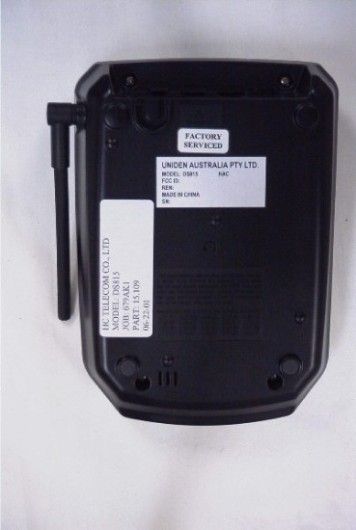
HC Telecom Co., Ltd. 4F., Chookhyup Bldg, #577 Songnae, Sosa, Puchon, Kyunggi, KOREA Telephone : +82 32 663-4488 FAX : +82 32 663-4489 FCC MARKING/LABELING FOR PART 68/15 FCC ID : ON7DS815 UNIDEN MODEL NO : DS815 Complies With Part 68, FCC Rules FCC Registration No. : Ringer Equivalence : HC Telecom Co., Ltd. MADE IN KOREA USE STANDARD JACK : USOC RJ11C THIS DEVICE COMPLIES WITH PART 15 OF THE FCC RULES. OPERATION IS SUBJECT TO THE FOLLOWING TWO CONDITIONS : (1) THIS DEVICE MAY NOT CAUSE HARMFUL INTERFERENCE, AND (2) THIS DEVICE MUST ACCEPT ANY INTERFERENCE RECEIVED, INCLUDING INTERFERENCE THAT MAY CAUSE UNDESIRED OPERATION. HC Telecom Co., Ltd. / DS815 EXHIBIT H
ID Label/Location Info
HC Telecom Co., Ltd. 4F., Chookhyup Bldg, #577 Songnae, Sosa, Puchon, Kyunggi, KOREA Telephone : +82 32 663-4488 FAX : +82 32 663-4489 Location of Label BOTTOM SIDE OF BASE UNIT LABEL
Operational Description
BASE UNIT The signal which inputed in TEL-LINE is DC coupled at T100 and transformed Analog into U1. DATA which is transformed into Digital signal is mixed with PN code at U1 (by spread spectrum) and transmitted to RF section.. Spreading signal which inputed to RF section is mixed with carrier supplied to VCO at IC1 and create TX frequency of using channel and then is transmitted to ANTENNA by TX control of IC2. The signal received to antenna is transmitted to IC1 by RX/TX control time. The signal inputed at 7pin of IC1 is mixed carrier of VCO and got to direct conversion and create Base band signal. And then, create I and Q signal by demodulation (QPSK : Quadrature Phase Shift Keying method is phase- shifted by 90° ) I and Q signal (Two signal phase is 90°) is transmitted to U1 of Base and remixed with PN code and generated Digital signal. This audio signal is passed through T100 and transmitted to TEL-LINE. ID setting : Press flash + No.(1~7) key of handset. And place on cradle of base unit. Base and handset detect charge condition both. Base and handset send and receive ID data each other using RF. Y1 is X-tal generating RF - reference signal. Q3 is charge detect circuitry. HANDSET The signal which is inputed to MIC is transformed Analog into Digital at U1. DATA which is transformed into Digital signal is mixed with PN code at U1. (by spread spectrum) and transmitted to RF section. Spreading signal which inputed to RF section is mixed with carrier supplied to VCO at IC1 and create TX frequency of using channel and then is transmitted to ANTENNA by TX control of IC2. The signal received to antenna is transmitted to IC1 of RF by RX/TX control time. The signal inputed at 7 pin of IC1 is mixed carrier of VCO and got to direct conversion And create Base band signal. And then, create I and Q signal by demodulation (QPSK : Quadrature Phase Shift Keying method is phase- shifted by 90° ) I and Q signal (Two signal phase is 90°) is transmitted to U1 and remixed with PN code and generated Digital signal. Digital signal is transformed into Analog at U1. This audio signal is passed through RECEIVER and transmitted. Y1 is X-tal generating RF - reference signal.
Test Report
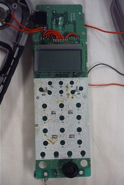
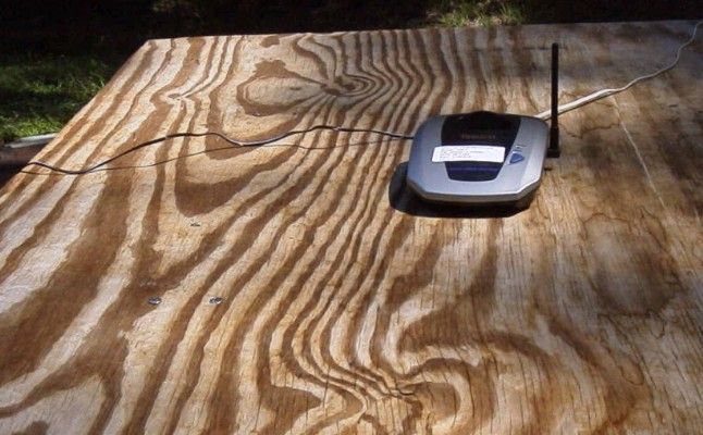
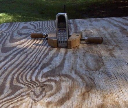
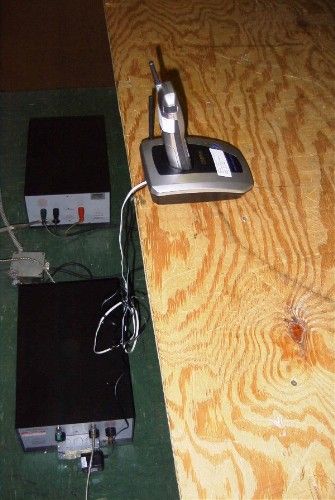
APPLICANT: HC TELECOM CO., LTD. FCC ID: ON7DS815 REPORT #: H\HCT\679WCK1\679WCK1TestReport.doc PAGE #: TABLE OF CONTENTS TABLE OF CONTENTS LIST APPLICANT: HC TELECOM CO., LTD. FCC ID: ON7DS815 TEST REPORT: PAGE 1..........SECURITY CODING INFORMATION PAGE 2-3........TEST PROCEDURE AND TEST EQUIPMENT LIST PAGE 4..........POWER LINE CONDUCTED INTERFERENCE PAGE 5-8........POWER LINE CONDUCTED PLOTS PAGE 9..........OCCUPIED BANDWIDTH AND PEAK POWER OUTPUT PAGE 10-11......6 dB BANDWIDTH PLOTS PAGE 12.........RADIATED SPURIOUS EMISSIONS BASE PAGE 13.........RADIATED SPURIOUS EMISSIONS HANDSET PAGE 14.........POWER SPECTRAL DENSITY AND PROCESSING GAIN PAGE 15-20......POWER SPECTRAL DENSITY PLOTS EXHIBITS: EXHIBIT 1........FCC ID LABEL SAMPLES EXHIBIT 2A-2B....SKETCH OF LABEL LOCATIONS EXHIBIT 3........BLOCK DIAGRAM EXHIBIT 4A-4B....SCHEMATICS - BASE EXHIBIT 5........SCHEMATIC - HANDSET EXHIBIT 6A.......EXTERNAL PHOTO – FRONT VIEW – BASE EXHIBIT 6B.......EXTERNAL PHOTO – BOTTOM VIEW – BASE EXHIBIT 6C.......EXTERNAL PHOTO – FRONT VIEW – HANDSET EXHIBIT 6D.......EXTERNAL PHOTO – BOTTOM VIEW – HANDSET EXHIBIT 6E.......INTERNAL COMPONENT SIDE PHOTO - BASE EXHIBIT 6F.......INTERNAL SOLDER SIDE PHOTO - BASE EXHIBIT 6G.......INTERNAL COMPONENT SIDE PHOTO – HANDSET EXHIBIT 6H.......INTERNAL SOLDER SIDE PHOTO - HANDSET EXHIBIT 7A-7P....INSTRUCTION MANUAL EXHIBIT 8A-8B....CIRCUIT DESCRIPTION EXHIBIT 9A.......RADIATED TEST SET UP PHOTO - BASE EXHIBIT 9B.......RADIATED TEST SET UP PHOTO - HANDSET EXHIBIT 9C.......POWERLINE CONDUCTED TEST SET UP PHOTO EXHIBIT 10A-10C..PROCESSING GAIN TEST DATA APPLICANT: HC TELECOM CO., LTD. FCC ID: ON7DS815 REPORT #: H\HCT\679WCK1\679WCK1TestReport.doc PAGE #: 1 OF 20 APPLICANT: HC TELECOM CO., LTD. FCC ID: ON7DS815 15.214(d) THIS DEVICE COMPLIES WITH THE SECURITY CODE REQUIREMENTS OF 15.214(d)(1)(2) AND (3) BY MEANS OF THE FOLLOWING: THE EPROM IS CAPABLE OF 16 MILLION DIGIT CODING AND THE FACTORY WRITES THE SERIES IN PRODUCTION. THIS MEANS THAT EACH OF 16 MILLION INDIVIDUAL SECURITY CODES ARE REPEATED ONLY ONCE IN ANY CONSECUTIVELY PRODUCED UNIT. APPLICANT: HC TELECOM CO., LTD. FCC ID: ON7DS815 REPORT #: H\HCT\679WCK1\679WCK1TestReport.doc PAGE #: 2 OF 20 APPLICANT: HC TELECOM CO., LTD. FCCID : ON7DS815 TEST EQUIPMENT LIST 1. Spectrum Analyzer: HP 8566B-Opt 462, S/N 3138A07786, w/ preselector HP 85685A, S/N 3221A01400, Quasi-Peak Adapter HP 8565OA, S/N 3303A01690 & Preamplifier HP 8449B-OPT H02, S/N 3008A00372 2. Biconnical Antenna: Eaton Model 94455-1, S/N 1057 3. Biconnical Antenna: Electro-Metrics Model BIA-25, S/N 1171 4. Log-Periodic Antenna: Electro-Metrics Model EM-6950, S/N 632 5. Log-Periodic Antenna: Electro-Metrics Model LPA-30, S/N 409 6. Double-Ridged Horn Antenna: Electro-Metrics Model RGA-180, 1-18 GHz, S/N 2319 7. 18-26.3GHz Systron Donner Standard Gain Horn #DBE-520-20 8. Horn 40-60GHz: ATM Part #19-443-6R 9. Line Impedance Stabilization Network: Electro-Metrics Model ANS-25/2, S/N 2604 10. Temperature Chamber: Tenney Engineering Model TTRC, S/N 11717-7 11. Frequency Counter: HP Model 5385A, S/N 3242A07460 12. Peak Power Meter: HP Model 8900C, S/N 2131A00545 13. Open Area Test Site #1-3meters 14. Signal Generator: HP 8640B, S/N 2308A21464 15. Signal Generator: HP 8614A, S/N 2015A07428 16. Passive Loop Antenna: EMCO Model 6512, 9KHz to 30MHz, S/N 9706-1211 17. Dipole Antenna Kit: Electro-Metrics Model TDA-30/1-4, S/N 153 18. AC Voltmeter: HP Model 400FL, S/N 2213A14499 19. Digital Multimeter: Fluke Model 8012A, S/N 4810047 20. Digital Multimeter: Fluke Model 77, S/N 43850817 21. Oscilloscope: Tektronix Model 2230, S/N 300572 TEST PROCEDURE GENERAL: This report shall NOT be reproduced except in full without the written approval of TIMCO ENGINEERING, INC. Shielded interface cables were used in all cases except for cables connecting to the telephone line and the power cords. A test program was run which simulated a normal data transmission on a network. POWER LINE CONDUCTED INTERFERENCE: The procedure used was ANSI STAN- DARD C63.4-1992 using a 50uH LISN. Both lines were observed. The bandwidth of the spectrum analyzer was 10kHz with an appro- priate sweep speed. The ambient temperature of the UUT was 74°F with a humidity of 44%. BANDWIDTH 6.0dB: The measurements were made with the spectrum analyz- er's resolution bandwidth(RBW)=100kHz and the video bandwidth(VBW) =300KHz and the span set as shown on plot. APPLICANT: HC TELECOM CO., LTD. FCC ID: ON7DS815 REPORT #: H\HCT\679WCK1\679WCK1TestReport.doc PAGE #: 3 OF 20 APPLICANT : HC TELECOM CO., LTD. FCC ID : ON7DS815 TEST PROCEDURES CONTINUED POWER OUTPUT: The RF power output was measured at the antenna feed point by removing the permanent antenna and connecting the UUT to a peak power meter, HP Model No. 8900C. RADIATION INTERFERENCE: The test procedure used was ANSI STANDARD C63.4-1992 using a HEWLETT PACKARD spectrum analyzer with a prese- lector. The bandwidth(RBW) of the spectrum analyzer was 100kHz up to 1GHz and 1.0MHz above 1GHz with an appropriate sweep speed. The VBW above 1.0GHz was = 1.0MHz. The analyzer was calibrated in dB above a microvolt at the output of the antenna. The ambient temperature of the UUT was 82°F with a humidity of 37%. 15.247(d) POWER SPECTRAL DENSITY. The peak within the pass band was located with a RBW set to 30Khz and a span of 5MHz, slightly greater than the 6dB bandwidth, then the emission was centered on the display and the span and RBW reduced. A 1.5MHz span, 3kHz RBW, and a sweep time to sweep time set to 500 seconds. Since spectral line spacing could not be resolved, the noise power density method was used. The reponse was then plotted, a correction factor of 35dB and any attenuation used was added. 15.247(e): PROCESSING GAIN, This gain is supplied by the manufacturer of the UUT. 2.1033(b)(4) ANTENNA AND GROUND SYSTEM: This unit uses a short, antenna element for the base unit and the handset. The antenna is permanently attached to the unit and no provision is made for conn…
Text truncated - open the document above for the full version.
Contact Information
Applicant
Hyo-Jong Lee(President)
82-32-663-4488Fax: 82-32-663-4489
Test Firm
Timco Engineering, Inc.S Sanders
Technical Specifications
| # | Rule Parts | Frequency Range | Power Output |
|---|---|---|---|
| 2 | 15C | 902 MHz - 928 MHz | 37.00 µW |
Other Applications from HC Telecom Co Ltd
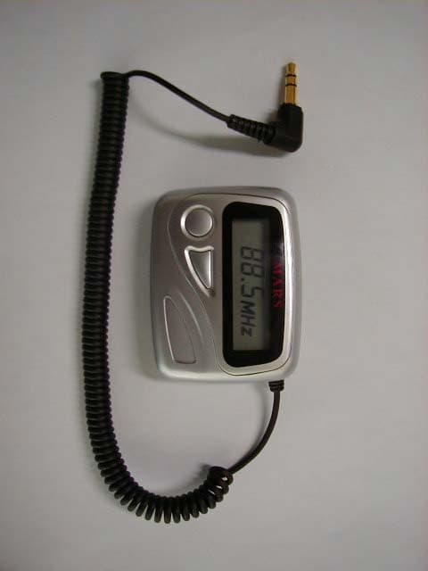
ON7HCF-3000
Feb 26, 2004FM TRANSCEIVER
Equipment Class
DXX - Part 15 Low Power Communication Device Transmitter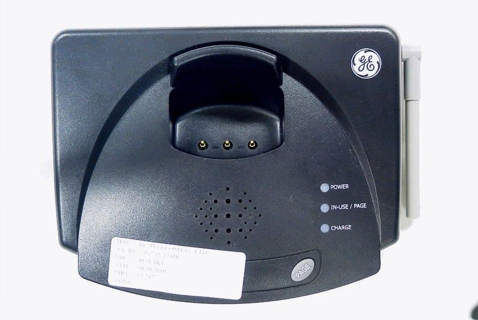
ON7AU27018
Oct 21, 2001900MHz DSS Cordless Phone
Equipment Class
DSS - Part 15 Spread Spectrum Transmitter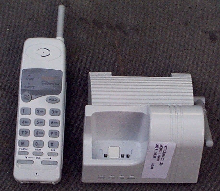
ON7HD-950
Oct 18, 1999900 MHz DSS Cordless Telephone
Equipment Class
DSS - Part 15 Spread Spectrum Transmitter