OOJTCELL1900TMTransCell 1900TM
OpenCell Corp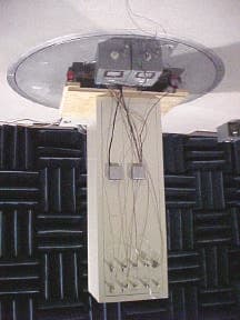
Click to zoom
Application Details
- Equipment Class
- PCB - PCS Licensed Transmitter
- Date of Grant
- Jul 17, 2001
- Application Purpose
- Original Equipment
- Date of Application
- May 17, 2001
- Equipment Note
- TransCell 1900TM
- Frequency Range
- 1930.00000000 - 1990.00000000
- Company
- OpenCell Corp
- Country
- United States
Documents & Files
Document Text
Text extracted from the exhibit documents filed with the FCC. Open a document above to read the original.
Users Manual
TRANSCEPT PROPRIETARY TRANSCEPT PROPRIETARY TransCell 1900TM System Installation & Integration Manual Document No. 1000462 March 20, 2001 Revision A THIS DOCUMENT CONTAINS PROPRIETARY INFORMATION OF TRANSCEPT, INC. AND IS TO BE USED ONLY IN ACCORDANCE WITH THE NONDISCLOSURE AGREEMENT UNDER WHICH THIS DOCUMENT IS PROVIDED. THIS DOCUMENT IS NOT TO BE DUPLICATED IN WHOLE OR IN PART WITHOUT PRIOR WRITTEN PERMISSION FROM A DULY AUTHORIZED REPRESENTATIVE OF TRANSCEPT, INC. THE REVISION STATUS OF ALL PAGES IN THIS DOCUMENT IS THE SAME AS THAT STATED ON THIS COVER. TRANSCEPT PROPRIETARY TRANSCEPT PROPRIETARY TransCell 1900TM System Installation & Integration Manual March 20, 2001 REVIEW AND CONCURRENCE C. Straw - Signature on File04/13/01 CHRIS STRAW, SYSTEMS ENGINEERDATE T. Hebert - Signature on File04/24/01 THOMAS HEBERT, DIR, DIGITAL TECHNOLOGIESDATE T. Hebert for S. Maniglia - Signature on File04/24/01 STEVE MANIGLIA, TDMA PROJECT MANAGERDATE THIS DOCUMENT CONTAINS PROPRIETARY INFORMATION OF TRANSCEPT, INC. AND IS NOT TO BE USED FOR ANY PURPOSE, EXCEPT IN ACCORDANCE WITH CONTRACTUAL NONDISCLOSURE TERMS. THIS DOCUMENT IS NOT TO BE DUPLICATED IN WHOLE OR IN PART WITHOUT PRIOR WRITTEN PERMISSION FROM A DULY AUTHORIZED REPRESENTATIVE OF TRANSCEPT. Document No. 1000462 Revision A March 20, 2001 TRANSCEPT PROPRIETARY TRANSCEPT PROPRIETARY DRAWING NO. 1000462 DOCUMENT CHANGE HISTORY DATEREVDESCRIPTIONAPPD 04/05/01ARel to ECO Control RN 010404km/CS Copyright 2001 Transcept, Inc. All rights reserved. TransCell 1900TMSystem Installation & Integration Manual1000462 A Page i TRANSCEPT PROPRIETARY - DATA ON THIS PAGE SUBJECT TO RESTRICTIONS CITED ON COVER AND TITLE TABLE OF CONTENTS SectionPage 1.0SCOPE..................................................................................................................................1 1.1REFERENCE DOCUMENTATION................................................................................................1 2.0PRODUCT SPECIFICATIONS............................................................................................1 3.0ASSET RESPONSIBILITY...................................................................................................1 4.0REMOTE SITE INSTALLATION..........................................................................................2 4.1TOWER TOP VIEW..............................................................................................................2 4.2REMOTE CABLING REQUIREMENTS..........................................................................................3 4.3MICROWAVE DATA LINK CABLES.............................................................................................5 4.4DATA LINK ANTENNA CLEARANCE...........................................................................................6 4.5REMOTE ASSEMBLY INTERCONNECT.......................................................................................7 4.6REMOTE PRIME POWER FEED.................................................................................................8 4.7REMOTE ASSEMBLY OUTLINE DIMENSIONS.............................................................................9 5.0HUB SITE INSTALLATION...............................................................................................11 5.1TOWER TOP VIEW.................................................................................................................11 5.2HUB CABLING REQUIREMENTS..............................................................................................12 5.3HUB ASSEMBLY INTERCONNECT...........................................................................................13 5.4BIAS TEE ALARMING..............................................................................................................13 5.5HUB PRIME POWER FEED.....................................................................................................14 5.6HUB ASSEMBLY OUTLINE DIMENSIONS..................................................................................15 5.7COMMUNICATION CONCEPT..................................................................................................18 5.8V.35 CABLING SCHEME.........................................................................................................19 DATA LINK ANTENNA ALIGNMENT..........................................................................................20 6.1.1Coarse Alignment........................................................................................................20 6.1.2Final Alignment............................................................................................................20 7.0RF PLANNING...................................................................................................................21 7.1DATA LINK ANTENNAS............................................................................................................21 7.2RF PLANNING MODEL.............................................................................................................23 7.2.1PCS Link Budget.........................................................................................................23 7.2.2Data Link Budget.........................................................................................................23 8.0ALTERNATE INSTALLATION SCHEMES.......................................................................23 8.1STANDARD CORRIDOR COVERAGE........................................................................................24 8.2SINGLE REPEATER INSTALLATION...........................................................................................25 8.3THREE SECTOR REPEATER....................................................................................................26 8.4THREE SECTOR SCHEME AT DONOR SITE...............................................................................27 8.5LARGE RADIUS COVERAGE..................…
Text truncated - open the document above for the full version.
Users Manual
TRANSCEPT PROPRIETARY TRANSCEPT PROPRIETARY TransCell 1900TM System Operation and Maintenance Manual Document No. 1000497 Revision A 08 March 2001 THIS DOCUMENT CONTAINS PROPRIETARY INFORMATION OF TRANSCEPT, INC. AND IS TO BE USED ONLY IN ACCORDANCE WITH THE NONDISCLOSURE AGREEMENT UNDER WHICH THIS DOCUMENT IS PROVIDED. THIS DOCUMENT IS NOT TO BE DUPLICATED IN WHOLE OR IN PART WITHOUT PRIOR WRITTEN PERMISSION FROM A DULY AUTHORIZED REPRESENTATIVE OF TRANSCEPT, INC. THE REVISION STATUS OF ALL PAGES IN THIS DOCUMENT IS THE SAME AS THAT STATED ON THIS COVER. Copyright 1999, 2001 Transcept, Inc. All rights reserved. TRANSCEPT PROPRIETARY TRANSCEPT PROPRIETARY TransCell 1900TM Operation and Maintenance Manual REVIEW AND CONCURRENCE C. STRAW, TDMA TECHNICAL LEADDATE S. Maniglia, TDMA Project ManagerDATE P. Yelle, TDMA Product ManagerDATE THIS DOCUMENT CONTAINS PROPRIETARY INFORMATION OF TRANSCEPT, INC. AND IS NOT TO BE USED FOR ANY PURPOSE, EXCEPT IN ACCORDANCE WITH CONTRACTUAL NONDISCLOSURE TERMS. THIS DOCUMENT IS NOT TO BE DUPLICATED IN WHOLE OR IN PART WITHOUT PRIOR WRITTEN PERMISSION FROM A DULY AUTHORIZED REPRESENTATIVE OF TRANSCEPT. Document No. 1000497 Revision A: 08 March 2001 TRANSCEPT PROPRIETARY TRANSCEPT PROPRIETARY DRAWING NO. DOCUMENT CHANGE HISTORY DATEREVDESCRIPTIONAPPD 03/08/01ARel to ECO control per RN 010308km/CS TransCell 1900TMOperation and Maintenance Manual1000497A Page i TRANSCEPT PROPRIETARY - DATA ON THIS PAGE SUBJECT TO RESTRICTIONS CITED ON COVER AND TITLE TABLE OF CONTENTS SectionPage 1.0INTRODUCTION..........................................................................................................1-1 1.1ABOUT THIS MANUAL..........................................................................................................1-1 1.1.1Scope.........................................................................................................................1-1 1.1.2Manual Organization..................................................................................................1-1 1.2TERMINOLOGY, ACRONYMS, AND ABBREVIATIONS...............................................................1-2 1.2.1Notation Conventions................................................................................................1-2 1.2.2Acronyms and abbreviations.....................................................................................1-2 1.3REFERENCE DOCUMENTATION............................................................................................1-3 1.4SYSTEM OVERVIEW.............................................................................................................1-4 1.4.1System Configuration................................................................................................1-4 1.4.2Physical Description..................................................................................................1-5 1.4.3Hub Subsystem Assemblies......................................................................................1-7 1.4.3.1Data Link Module (DLM)....................................................................................1-7 1.4.3.2Hub Transceiver Module (HTM)........................................................................1-8 1.4.3.3Signal Processing Module (SPM)......................................................................1-9 1.4.3.4Hub Interface Tray Assy.....................................................................................1-9 1.4.3.5Low Voltage Power Supply (LVPS).................................................................1-10 1.4.3.6Microwave Antenna..........................................................................................1-10 1.4.3.7Cable Assemblies............................................................................................1-11 1.4.4Remote Subsystem Assemblies.............................................................................1-11 1.4.4.1Remote Transceiver Module (RTM).................................................................1-12 1.4.4.2Data Link Module..............................................................................................1-13 1.4.4.3Remote Power Supplies..................................................................................1-13 1.4.4.4Remote Interface Tray Assembly....................................................................1-14 1.4.4.5Transmitter Tray Assembly..............................................................................1-15 1.4.4.6Tower Top Alarm Module (TTA).......................................................................1-15 1.4.4.7Microwave Antenna..........................................................................................1-16 1.4.4.8Cable Assemblies............................................................................................1-16 1.4.5Communication Interfaces.......................................................................................1-16 1.4.5.1Hardware/Software Platform Requirements for HRP User Interface..............1-16 1.4.5.2Network Interface.............................................................................................1-16 1.4.5.3System Element Manager (SEM) Interface.....................................................1-17 1.4.5.4HRP User Interface (HUI).................................................................................1-17 1.4.5.5HRP Command Language...............................................................................1-18 1.5SEM STARTUP...................................................................................................................1-18 1.5.1User Access.............................................................................................................1-18 1.5.2SEM and HUI Workstation Initialization...................................................................1-18 1.5.3SEM Workstation Shutdown.............................................................…
Text truncated - open the document above for the full version.
Cover Letter(s)
FCC ID: OOJTCELL1900TM Request for Confidentiality In accordance with 47 C.F.R. Section 0.459, we, Transcept, Inc., hereby request confidentiality for the block diagrams, schematics and product descriptions presented for certification. In support of the Request for Confidentiality, the following is stated: Enclosed within this application is technical information which we deem to be trade secrets and proprietary. If made public, the information might be used to our disadvantage. To assist in assuring that we receive the full value of our product and protect its competitive posture, we respectfully request this grant of confidentiality. Transcept, Inc.
External Photos
NTS Test Report Number: 36864-01C-FCC, Rev. 1 10 of 92 Radiated Emissions Test Setup Remote Unit HUB Comments The Transcell TDMA 1900 System Consisting Of One Dual HUB And One Remote Unit conformed to the requirements of FCC 47 CFR Part 15, Sub-Class C. Emissions were below the limit over the entire frequency range. Reference Appendix B for Radiated Emissions Plot Sheets. 6.0Conducted Emissions (AC Power Leads Voltage) 6.1Conducted Emissions (AC Power Leads Voltage) Test Procedure Conducted measurements were made with power supplied to the Transcell TDMA 1900 System Consisting Of One Dual HUB And One Remote Unit; support equipment not part of the Transcell TDMA 1900 System was powered through a similar but separate LISN. Each of the Transcell TDMA 1900 System's input power leads were scanned first with a peak detector. The highest peak amplitudes relative to the appropriate limits were identified and re-measured using a quasipeak detector. At least six of all peaks closest to the respective limits were recorded in this report. The conducted emissions test was performed using NTS' automatic EMI test equipment. This equipment utilized HP EMI measurement software running on a HP computer that interfaced directly with HPIB (IEEE) compatible instruments with graphical displays presented on the spectrum analyzer's CRT, with hard copies of the data generated by a plotter. The program automatically selects the range of test frequencies or band, and sets the specification line limits to be used during the test. This equipment/software allows for real time data reduction and prints tabulated data on peak value or quasi-peak value measurements. NTS Test Report Number: 36864-01C-FCC, Rev. 1 12 of 92 Conducted Emissions Test Setup Remote Unit HUB Comments The Transcell TDMA 1900 System conformed to the requirements the Conducted Emission (AC Power Leads Voltage) Test. Emissions were below the limit over the entire frequency range. Reference Appendix C for Conducted Emissions Plot Sheets.
ID Label/Location Info
REVISION HISTORY REV DESCRIPTION DATE APPROVED UNLESS OTHERWISE SPECIFIED DIMENSIONS ARE IN INCHES TOLERANCES .XX DECIMAL ± NONE .XXX DECIMAL ± NONE ANGLES ± NONE SURFACE QUALITY ± NONE THIRD ANGLE PROJECTION CONTRACT NO DRAWN DATE APVD DATE CHECKED DATE APVD DATE APVD DATE APVD DATE APVD DATE Manchester, NH 03103-3353 SIZE DWG NO A SCALE SHEET NONE 1 of 2 THE REVISION STATUS OF ALL SHEETS OF THIS DRAWING IS THE SAME AS SHEET 1 NEXT ASSY USED ON APPLICATION Transcept Proprietary. – Transcell 1900TM FCC Label, REMOTE Xxxxx C. Straw 02/15/01 ENGINEERING USE ONLY SIZE DWG NO REV A – SCALE SHEET NONE 2 of 2 Transcept Proprietary. FCC Class B FCC ID: OOJTCELL1900TM This device complies with parts 15 and 24 of the FCC Rules. Operation is subject to the following two conditions: (1) This device may not cause harmful interference, and (2) this device must accept any interference received, including interference that may cause undesired operation. TDMA Remote Assy
ID Label/Location Info
REVISION HISTORY REV DESCRIPTION DATE APPROVED UNLESS OTHERWISE SPECIFIED DIMENSIONS ARE IN INCHES TOLERANCES .XX DECIMAL ± NONE .XXX DECIMAL ± NONE ANGLES ± NONE SURFACE QUALITY ± NONE THIRD ANGLE PROJECTION CONTRACT NO DRAWN DATE APVD DATE CHECKED DATE APVD DATE APVD DATE APVD DATE APVD DATE Manchester, NH 03103-3353 SIZE DWG NO A SCALE SHEET NONE 1 of 2 THE REVISION STATUS OF ALL SHEETS OF THIS DRAWING IS THE SAME AS SHEET 1 NEXT ASSY USED ON APPLICATION Transcept Proprietary. – Transcell 1900TM FCC Label, REMOTE Xxxxx C. Straw 02/15/01 ENGINEERING USE ONLY SIZE DWG NO REV A – SCALE SHEET NONE 2 of 2 Transcept Proprietary. FCC Class B FCC ID: OOJTCELL1900TM This device complies with parts 15 and 24 of the FCC Rules. Operation is subject to the following two conditions: (1) This device may not cause harmful interference, and (2) this device must accept any interference received, including interference that may cause undesired operation. TDMA Remote Assy
Parts List/Tune Up Info
TRANSCEPT PROPRIETARY TRANSCEPT PROPRIETARY TransCell 1900TM Description Per 47 CFR 2.1033(c) Document No. Xy February 16, 2001 Revision – THIS DOCUMENT CONTAINS PROPRIETARY INFORMATION OF TRANSCEPT, INC. AND IS TO BE USED ONLY IN ACCORDANCE WITH THE NONDISCLOSURE AGREEMENT UNDER WHICH THIS DOCUMENT IS PROVIDED. THIS DOCUMENT IS NOT TO BE DUPLICATED IN WHOLE OR IN PART WITHOUT PRIOR WRITTEN PERMISSION FROM A DULY AUTHORIZED REPRESENTATIVE OF TRANSCEPT, INC. THE REVISION STATUS OF ALL PAGES IN THIS DOCUMENT IS THE SAME AS THAT STATED ON THIS COVER. TRANSCEPT PROPRIETARY TRANSCEPT PROPRIETARY TransCell 1900TM Description Per 47 CFR 2.1033(c) February 16, 2001 REVIEW AND CONCURRENCE CHRIS STRAW, SYSTEM ENGINEERDATE TOM HEBERT, SYSTEM ENGINEERING MANAGERDATE STEVE MANIGLIA, PROGRAM MANAGERDATE THIS DOCUMENT CONTAINS PROPRIETARY INFORMATION OF TRANSCEPT, INC. AND IS NOT TO BE USED FOR ANY PURPOSE, EXCEPT IN ACCORDANCE WITH CONTRACTUAL NONDISCLOSURE TERMS. THIS DOCUMENT IS NOT TO BE DUPLICATED IN WHOLE OR IN PART WITHOUT PRIOR WRITTEN PERMISSION FROM A DULY AUTHORIZED REPRESENTATIVE OF TRANSCEPT. Document No. X Revision – TRANSCEPT PROPRIETARY TRANSCEPT PROPRIETARY DRAWING NO. X DOCUMENT CHANGE HISTORY DATEREVDESCRIPTIONAPPD mm/dd/yy-Released for general distribution.xx/XXX Copyright 2001 Transcept, Inc. All rights reserved. TransCell 1900TM Description Per 47 CFR 2.1033(c) Document No. Xy – Page i TRANSCEPT PROPRIETARY - DATA ON THIS PAGE SUBJECT TO RESTRICTIONS CITED ON COVER AND TITLE TABLE OF CONTENTS SectionPage 1.047 CFR 2.1033(C) REQUIREMENTS..................................................................................1 1.1MAILING ADDRESS..................................................................................................................1 1.2FCC IDENTIFIER.....................................................................................................................1 1.3INSTALLATION AND OPERATION MANUALS................................................................................1 1.4TYPE OF EMISSION..................................................................................................................1 1.5FREQUENCY RANGE................................................................................................................1 1.6POWER LEVELS AND POWER CONTROL....................................................................................1 1.7MAXIMUM POWER LEVEL.........................................................................................................1 1.8DC CURRENT AND VOLTAGE SUPPLIED TO PA, OPERATIONAL RANGE......................................1 1.9TUNE UP PROCEDURE.............................................................................................................2 1.10SCHMATICS AND RF SHAPING..............................................................................................2 1.11FCC LABEL SUBMISSION.....................................................................................................2 1.12PHOTOGRAPHS OF TRANSCELL 1900TM.............................................................................4 1.13DIGITAL MODULATION.........................................................................................................7 1.1447 CFR SECTIONS 2.1046 THROUGH 2.1057.....................................................................7 1.15EXTERNAL TRANSMIT AMPLIFIER.........................................................................................8 1.16AM GENERATOR..................................................................................................................8 1.17COMPOSITE APPLICATION...................................................................................................8 LIST OF ILLUSTRATIONS FigurePage FIGURE 1. MAXIMUM RF OUTPUT POWER PER CARRIER....................................................................1 FIGURE 2: FCC LABEL, REMOTE........................................................................................................3 FIGURE 3: FCC LABEL PLACEMENT, REMOTE ENCLOSURE DOOR....................................................4 FIGURE 4: HUB CHASSIS...................................................................................................................5 FIGURE 5: REMOTE CHASSIS............................................................................................................5 FIGURE 6: PAPS AT REMOTE ENCLOSURE........................................................................................6 FIGURE 7: TRANSMITTER POWER AMPLIFIER RACK............................................................................6 FIGURE 8: REMOTE ENCLOSURE, FRONT AND REAR VIEW.................................................................7 LIST OF TABLES TablePage TABLE 1. DC SUPPLY PARAMETERS AT POWER AMPLIFIER................................................................2 TransCell 1900TM Description Per 47 CFR 2.1033(c) Document No. Xy – Page 1 TRANSCEPT PROPRIETARY - DATA ON THIS PAGE SUBJECT TO RESTRICTIONS CITED ON COVER AND TITLE 1.0 47 CFR 2.1033(C) REQUIREMENTS Each requirement of paragraph (c) is handled separately below. 1.1 MAILING ADDRESS The full mailing address and recipient of the grant are covered in 1900TM.PDF. 1.2 FCC IDENTIFIER The FCC Identifier, OOJTCELL1900TM, is covered in 1900TM.PDF. 1.3 INSTALLATION AND OPERATION MANUALS Draft copies of the O&M and installation manuals have been furnished by Transcept as Exhibit D. 1.4 TYPE OF EMISSION The type of emission for Part 24 is TDMA. The Part 15 emission is spread spectrum at 5.8 GHz. 1.5 FREQUENCY RANGE The TransCell 1900TM Part 24 emissions are located in the PCS bands A-F. The Part 15 emissions are in the ISM 5.8 GHz band. 1.6 POWER LEVELS AND POWER CONTROL The control of transmit power levels is discussed in document #1000483, SEM and HUI User manual, as furnished by Transcept. Operational power level for the Part 24 transmitter is 10 Watts per carri…
Text truncated - open the document above for the full version.
RF Exposure Info
TransCell 1900TM 47CFR2.10XX Compliance Document No. X24 – Page i TRANSCEPT PROPRIETARY - DATA ON THIS PAGE SUBJECT TO RESTRICTIONS CITED ON COVER AND TITLE TransCell 1900TM 47CFR2.10XX Compliance Document No. X24 March 9, 2001 Revision – T HIS DOCUMENT CONTAINS PROPRIETARY INFORMATION OF TRANSCEPT, INC. AND IS TO BE USED ONLY IN ACCORDANCE WITH THE NONDISCLOSURE AGREEMENT UNDER WHICH THIS DOCUMENT IS PROVIDED. THIS DOCUMENT IS NOT TO BE DUPLICATED IN WHOLE OR IN PART WITHOUT PRIOR WRITTEN PERMISSION FROM A DULY AUTHORIZED REPRESENTATIVE OF TRANSCEPT, INC. T HE REVISION STATUS OF ALL PAGES IN THIS DOCUMENT IS THE SAME AS THAT STATED ON THIS COVER . TransCell 1900TM 47CFR2.10XX Compliance Document No. X24 – Page ii TRANSCEPT PROPRIETARY - DATA ON THIS PAGE SUBJECT TO RESTRICTIONS CITED ON COVER AND TITLE TABLE OF CONTENTS Section Page 1.0 47CFR2.1033...................................................................................................................1 1.1 2.1033 C(4).......................................................................................................................1 1.2 2.1033 C(12).....................................................................................................................1 1.3 2.1033 C(13).....................................................................................................................2 2.0 47CFR2.1046...................................................................................................................3 2.1 2.1046 A, C.......................................................................................................................3 3.0 47CFR2.1047D................................................................................................................4 4.0 47CFR2.1049...................................................................................................................4 4.1 2.1049 C............................................................................................................................4 4.2 2.1049 C(4).......................................................................................................................4 5.0 47CFR2.1051...................................................................................................................5 6.0 47CFR2.1053...................................................................................................................5 7.0 47CFR2.1055...................................................................................................................5 8.0 47CFR2.1057...................................................................................................................5 LIST OF ILLUSTRATIONS Figure Page F IGURE 1-1. TYPICAL PCS FLAT PANEL ANTENNA.........................................................................1 F IGURE 1-2. TYPICAL ISM DISH ANTENNA. ...................................................................................2 F IGURE 1-3. 5.8 GHZ SPREAD SPECTRUM....................................................................................3 F IGURE 2-1. SPECTRUM ANALYZER POWER MEASUREMENT ALGORITHM........................................4 F IGURE 4-1. TDMA INPUT SIGNAL.................................................................................................5 TRANSCEPT PROPRIETARY TRANSCEPT PROPRIETARY In addition to exhibits already submitted, the following details are furnished in response to the notice generated by Elite regarding outstanding issues with the current application for FCC certification of the TransCell 1900TM system. 1.0 47CFR2.1033 This section had been written up as of February 16 th as a separate document, 47cfr2_1033.pdf . Please refer to 47cfr2_1033.pdf for sections not appearing here. Also, these sections supercede the equivalent sections in 47cfr2_1033.pdf . 1.1 2.1033C(4) The TransCell 1900TM system is an intentional radiator which employs two transmitter types. One type is designed for PCS frequency transmission of TIA/EIA-136 “TDMA” modulated signals under 47CFR Part 24. The other transmission type is designed for point-to-point data-link communications utilizing spread spectrum techniques in the ISM band under 47CFR Part 15.247. However, the requirement for this second transmitter description falls under 47CFR2.1033B, not paragraph c(4). 1.2 2.1033C(12) In addition to photos furnished by Transcept in exhibits C and D, and in 47cfr2_1033.pdf, the following figures are offered. Figure 1-1. Typical PCS Flat Panel Antenna. TRANSCEPT PROPRIETARY TRANSCEPT PROPRIETARY Figure 1-2. Typical ISM Dish Antenna. 1.3 2.1033C(13) The only digital modulation present in the TransCell 1900TM system is the data-link bit stream covered in 47cfr15.247. It utilizes 11 megabits per second CCK. A digitized (base- band) version of the original IF TDMA signal is digitally filtered and taken as input to be modulated as spread spectrum at 5.8 GHz. Three bits per packet are set aside for internal system communications. The resulting RF is shaped by a diplexer before transmission. A sample plot of this output is included in /15_247/attach4.tif of the CD-ROM furnished to NTS by Transcept. It has been reprinted in this section as Figure 1-3. At the data-link receiver, the 5.8 GHz signal is demodulated back to base-band and the internal system communications bits are stripped from the data stream in preparation for conversion to a TDMA analog IF. The original TDMA signal modulation and synthesis is done in the mobile handset and at the base station, outside of our system. TRANSCEPT PROPRIETARY TRANSCEPT PROPRIETARY Figure 1-3. 5.8 GHz Spread Spectrum. 2.0 47CFR2.1046 2.1 2.1046A, C The RF output measurements were made in conjunction with 47CFR part 24 testing. Therefore, please reference Exhibit E as furnished by Transcept for the following figures. Figure 4 shows the test setup. As shown in Figure 5 of the referenced document, the load is an Inmet 2N75W-30-296, which i…
Text truncated - open the document above for the full version.
Test Report
NTS Test Report Number: 36864-01C-FCC, Rev. 1 1 of 92 Compliance Report FCC 47 CFR PART 15, Sub-Class C For A Transcell TDMA 1900 System Consisting Of One Dual HUB And One Remote Unit Prepared For:Transcept, Inc. 955 Perimeter Rd Manchester, NH 03103-3353 P.O. Number: P0101696 Prepared By: National Technical Systems 1146 Massachusetts Avenue Boxborough, MA 01719 Issued: April 11, 2001 This report and the information contained herein represents the results of testing articles/products identified and selected by the client. The tests were performed to specifications and/or procedures approved by the client. National Technical Systems (“NTS”) makes no representations expressed or implied that such testing fully demonstrates efficiency, performance, reliability, or any other characteristic of the articles being tested, or similar products. This report should not be relied upon as an endorsement or certification by NTS of the equipment tested, nor does it present any statement whatsoever as to its merchantability or fitness of the test article or similar products for a particular purpose. This document shall not be reproduced except in full without written approval from National Technical Systems (“NTS”). NTS Test Report Number: 36864-01C-FCC, Rev. 1 2 of 92 REVISION PAGE Rev. NoDatePage No.Para. No.Description OriginalApril 03, 2001--- 1April 11, 2001B-43 through B-48-Remove …
Text truncated - open the document above for the full version.
Contact Information
Applicant
Steven Maniglia(Director of Engineering)
Technical Contact
TransceptChris Straw
[email protected](603) 645 - 5603
955 Perimeter Rd. · Manchester, New Hampshire · United States
Test Firm
National Technical Systems (NTS)Jeff Viel
Technical Specifications
| # | Rule Parts | Frequency Range | Power Output | Emission | Tolerance |
|---|---|---|---|---|---|
| 2 | 24E | 1.93 GHz - 1.99 GHz | 10 W | 34K6DXW | 0.05 ppm |
Other Applications from OpenCell Corp

OOJOPENCELLV2-1
Feb 17, 2004OpenCell Radio Access Node Version 2
Equipment Class
PCB - PCS Licensed Transmitter
OOJOPENCELLV1-1
Aug 06, 2002TNB - Licensed Non-Broadcast Station Transmitter
Equipment Class
TNB - Licensed Non-Broadcast Station Transmitter