OPLSPR250MGround Penetrating Radar
U.S. Radar, Incorporated
Click to zoom
Application Details
- Equipment Class
- UWB - Ultra Wideband Transmitter
- Date of Grant
- May 10, 2000
- Application Purpose
- Original Equipment
- Date of Application
- Nov 13, 1999
- Equipment Note
- Ground Penetrating Radar
- Frequency Range
- 2.00000000 - 1000.00000000
- Company
- U.S. Radar, Incorporated
- Country
- United States
Documents & Files
Document Text
Text extracted from the exhibit documents filed with the FCC. Open a document above to read the original.
Users Manual
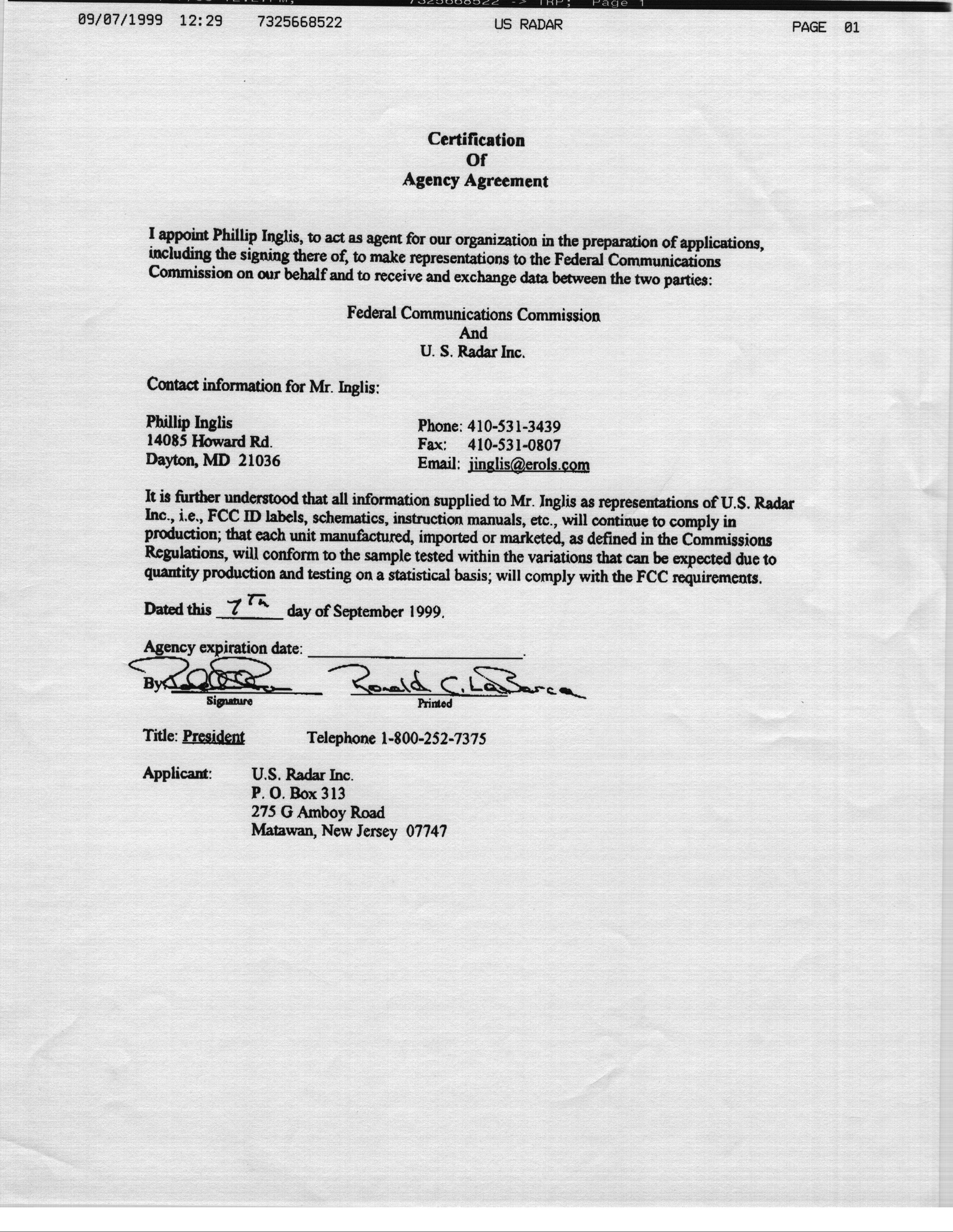
Addendum to the System Hardware Manual to Comply with the FCC part 15 Waiver Requirements The following page shall be fixed to the rear of the front cover of all manuals issued in the United States of America Compliance with the FCC waiver permitting the use of SPRscan in the United States of America The use of the SPRscan in the United States of America is regulated by the FCC Part 15 Waiver issued to US Radar Inc. For the user, this means that a number of procedures and methods of working should be adhered to. • The proximity sensor and Dead Man’s Handle should be calibrated for use every time the system is operated. • Records should be kept of when, where and by whom the SPRscan was operated. A log book is the best way to achieve this. • Inform US Radar Inc of your area of operations, who will then inform the FCC of the details. Note : SPRscan is generally prohibited from use within 1 statute mile of any airport, SARSAT or NOAA meteorological satellite earth station, any facilities of the National Radio Astronomy Observatory and of the National Radio Astronomy and Ionospheric Centre, navigable waterway or critical GPS based radio-navigation station, without specific event coordination with the national spectrum management staffs of the FAA, Department of Commerce, National Science Foundation and the US Coast Guard as appropriate. Refer to the distributor for information on how to coordinate these operations The following restrictions apply: • Airborne operation of the system is not permitted. The system must be operated with the antenna in contact with and directed into the ground being surveyed. • Users must notify distributors of change of ownership or address. • Any modification that affects the conformity of the SPRscan system with section 15.209 of the Commission’s Rules are forbidden. Any unauthorised modifications could result in the user losing their legal authority to use the equipment. NOTICE This device complies with part 15 of the FCC Rules. Operation is subject to the following two conditions. (1) This device may not cause harmful interference, and (2) this device must accept any interference received, including interference that may cause undesired operation. The operation of this equipment is authorised under a waiver issued by the FCC. If it is determined that the operation of this equipment causes harmful interference to authorised radio operations, the operator shall immediately cease operations and contact the Compliance and Information Bureau of the FCC.
Users Manual
SPRscan Manual Hardware Ref: SPR0002 Issue: 001 26 May 1998 2 Copyright information page Copyright 1998 No part of this document may be photocopied or otherwise reproduced without the prior permission in writing of ERA Technology Ltd. Such written permission must also be obtained before any part of this document is stored in an electronic system of whatever nature. 3 Using this handbook This handbook has been written to provide the SPRscan user with clear, concise instructions in the assembly and care of the radar. In order to avoid repeating sets of instructions, icons have been used to inform the user which assembled components are required for a particular section. If an icon appears in the requirements section, turn to the pages describing the assembly of that component and follow them carefully. Key Controller Antenna with radar head installed Pull handle system 1 GHz antenna system with radar head installed Harness system Warning 4 Contents Copyright information page2 Using this handbook3 Contents4 Parts Lists7 SPRscan3D System7 Option : Trolley System8 Option : Trolley Rough Ground Option9 Option : 1 GHz Antenna System10 Option : 2 GHz Antenna System11 Option : 250 MHz Antenna12 Modes of Operation13 Description of Parts16 Controller16 Head Electronics Unit17 General Antenna18 1 GHz antenna19 Function Handle20 Trolley21 General Assembly of parts22 Controller22 Installing the Head Electronics unit into an antenna or antenna belt case 23 The pull handle system25 Assembly of pull handle25 Attaching the handle to the antenna26 Setting up for field use27 Connecting the antenna/Head Electronics unit combination to the controller27 One-Man Harness Operation27 Using the harness – 500/250 MHz27 5 Using the harness – 1 GHz backpack29 The Standard Trolley Option30 Adding the antenna30 Adding the controller31 The Rough Ground Option31 Pictorial Guide To Assembling the System32 Proximity Sensor Calibration36 Calibration Procedure36 Dead Man’s Handle36 Using Optional Peripherals38 Standard System : Technical Specifications39 Controller39 Control39 Display39 I/O provision39 Software39 System Scan Modes40 Head Electronics Unit (Tx-Rx)40 500 MHz Antenna (P – 0500)40 Environmental & build specifications40 SPRscan Standard Parts List as supplied (+ shipping weight in kg)41 Antennas : Technical Specifications42 Model P-0250 250 MHz42 Model P-0500 500 MHz42 Model P-1000 1000 MHz42 Model P-2000 2000 MHz42 Optional extras43 Limitations on using the SPRscan44 Maintaining the SPRscan System45 Cleaning the System45 6 Distributor and Technical Support Contact Information46 Manufacturer46 Distributors46 United Kingdom – Home Counties and London46 Belgium47 Czech Republic47 Germany and Austria, Luxembourg, Netherlands, Switzerland47 Italy47 South Korea48 United States of America48 SPRscan Electromagnetic Compatibility (EMC)52 7 Parts Lists The following section illustrates the component parts supplied with each SPRscan option SPRscan3D System 1 500 MHz antenna10 Display visor 2 Head electronics unit11 Manuals 3 Controller unit12 Document and software pack 4 Battery packs – 2 off13 Carry cases – 2 off 5 Battery chargers – 2 off14 Keyboard 6 2 m data cable15 Mouse 7 Power cable16 Carry harness 8 Mains adapter17 Function handle 9 Handle system 8 Option : Trolley System 1 Wheels with integral shaft encoder 5 Transit case (not illustrated) 2 Battery bag 6Tool roll (not illustrated) 3 Computer handle assembly 7Spare wheel 4 Wheel covers, on wheels 8Handles 9 Option : Trolley Rough Ground Option 1 Rough Ground Option 2 Transit case 10 Option : 1 GHz Antenna System 1 Transit case 3 Head electronics unit with backpack 2 1 GHz antenna with sacrificial skid tray Note: The system illustrated shows a head electronics unit installed. This is NOT part of the 1 GHz option. 11 Option : 2 GHz Antenna System 1 Transit case 3 Head electronics unit with backpack 2 2 GHz antenna Note: The system illustrated shows a Head Electronics unit installed. This is NOT part of the 2 GHz option. 12 Option : 250 MHz Antenna 1 250 MHz antenna2 Transit case 3 Pull cable 13 Modes of Operation The following section illustrates some of the ways in which the SPRscan can be deployed in the field. The selection is not exhaustive but is intended to show the operator how flexible the system can be. Trolley Mode – with 500 MHz antenna 14 Trolley Mode – with 250 MHz antenna Two-man operation 15 One-man mode – with 1 GHz antenna. The 500 MHz antenna can also be used in this configuration Office mode 16 Description of Parts Controller 1Screen4 Function keys 2Bezel5 Cursor keys 3Power status lights6 Command keys 1Data Connector7 Mouse/serial port 2Power Supply Connector8 Keyboard socket 3Fuse9 External monitor socket 4Power on/off switch10 Carry harness connecting posts 5Floppy disk drive11 Protective cover fastening holes 6Parallel/printer port12 Protective cover (outline) for IP65 17 Head Electronics Unit Front 1Locking screws4Remote control/function grip socket 2Shaft encoder socket5Purge screw 3Data cable socket Back 1Strain relief lanyard socket3Transmit trigger (Tx trig) 2Transmit reference (Tx ref.)4Receiver 18 General Antenna The illustration below covers both the 500 and 250 MHz antennas. The numbered features are essentially common to both units. 1Side cheek4Pull cable locating hole 2Sacrificial skid tray5Head Electronics unit 3Handle locating hole 19 1 GHz antenna 11 GHz Antenna4Belt box 2Handle5Harness straps 3Handle locking lever6Sacrificial skid tray 20 Function Handle 1Stub handle socket5Locating pin to lock handle on stub 2Head Electronics unit connector6Stop button 3Pause button7Marker trigger switch 4Next button8Dead Man’s Handle 21 Trolley 1Pneumatic tyres7Head Electronics connector 2Battery bag8Bracket locking levers 3Shaft encoder9Main shaft adjusting knob 4Clevis10Clevis adjusting lever 5Computer handles11Function handle 6Controller locking bolts12Dummy handle 22 General Assembly of parts Controller 1. Remove the controller from the ca…
Text truncated - open the document above for the full version.
Block Diagram
System Block Diagram 4MHz Crystal Oscillator Radar timing and control signal generation ADC Averaging Sampler Variable gain RX input TX trig. Dead Man’s switch Rotary encoder via screened cable Position data Radar data 15V power TX ref . Control & I/F logic To antenna To Controller via screened cable Remote control data To Function Handle via screened cable Metal enclosure Control data Switched mode PSU DC power Divide by 4 1MHZ repetition rate
Cover Letter(s)
November 14, 1999 CONFIDENTIALITY REQUEST CONTAINED WITHIN Federal Communications Commission Authorization and Evaluation Division 7435 Oakland Mills Road Columbia, MD 21046 Re:U.S. Radar Inc., application for Ground Penetrating Radar FCC ID: OPLSPR250M Gentlemen: U.S. Radar Inc., P.O. Box 319 Matawan, New Jersey 007747 herein submits an Application for Equipment Authorization to be followed by submission of a check for $XXXX.XX along with Form 159 for certification of a ground penetrating radar under FCC Rules Part 15 as required by the waiver issued by the FCC to U.S. Radar. This application is submitted in accordance with the provisions of the waiver to show compliance under the terms of the waiver. U.S. Radar request, pursuant to 47CFR 0.459, post grant confidentiality for portions of the material contained in this application such that the identified material will be withheld from public inspection following the grant of this authorization. This material, as indicated by request for confidentiality of the items during the electronic submission process and further identified below includes: 1.Circuit diagrams submitted as Equipment Authorization Electronic Filing attachment: "schematics" Exhibit #5 2. Internal photos submitted as Equipment Authorization Electronic Filing attachment: "internal photos" Exhibit #9. Specifically, these exhibits contain information relating to circuit function and complexity that could be of benefit to competitors. The internal photos show design features of the radiating system that are unique to U.S. Radar. This material contains trade secrets and confidential information that U.S. Radar does not customarily release to the public and which is otherwise not generally available to the public. Please contact the undersigned by phone at 410-531-3439, by fax at 410-531-0807, by email at [email protected], or by correspondence at the address below if there are any further questions or additional information needed concerning this filing. Regards, (signed) Phillip Inglis 14085 Howard Rd. Dayton, MD. 21036
Cover Letter(s)
31030/4-3- 1300C2 Mr. Ronald C. LaBarca President U.S. Radar Inc. P. O. Box 319 Matawan, New Jersey 07747 Dear Mr. LaBarca: This is in reply to your letter of January 28, 1998, requesting a waiver of Part 15 of the Commission's rules to permit the authorization of a ground-penetrating radar system manufactured by ERA Technology and known as SPRscan. The SPRscan is an impulse radar system employing antennas centered at 250 MHz, 500 MHz, 1000 MHz and 2000 MHz. Specifically, you request a waiver of the prohibition against operation within the restricted bands ( ∋ 15.205), the prohibition against operation within the TV broadcast bands ( ∋ 15.209(a)), the application of a pulse desensitization correction factor ( ∋∋ 15.31 and 15.35), and the prohibition against employing a Class B, damped wave emission ( ∋∋ 2.201 and 15.5). In support of your waiver request, you state that emissions from the SPRscan are below 40 dBuV/m at a distance of 3 meters. This indicates that the equipment is capable of complying with our general emission limits in ∋ 15.209 of the rules. You also state that you will limit the marketing of this product to 25 units, that users will be required to maintain a log of operations, that the equipment will contain a "dead man's handle" which must be physically depressed to activate the transmitter, and that the equipment will contain a proximity sensor to ensure that the transmitter shuts off if the antenna is moved off of the surface being investigated. Based on these parameters, you express confidence that there is a low probability that interference would be caused to other radio operations. As the frequencies that will be used include several frequency bands allocated to the U.S. Government, we coordinated the waiver request with the National Telecommunications and Information Administration (NTIA). On June 15, 1999, NTIA informed us that the waiver can be granted with certain conditions. A copy of the NTIA letter and attachment setting forth the conditions is enclosed. It is a well-established principle that the Commission will waive its rules only if it determines, after careful consideration of all pertinent factors, that such a grant would serve the public interest without undermining the policy which the rule in question is intended to serve. WAIT Radio v. FCC, 418 F.2d 1153, 1157 (D.C. Cir. 1969). In discussing the treatment of requests for waivers of established rules, the court in WAIT Radio emphasized that the agency's discretion in applying general rules is intimately linked to the existence of "a safety valve procedure" to permit consideration of an application for exemption based on special circumstances. Id. Indeed, the court considered a rule most likely to be undercut if it does not take into account "considerations of hardship, equity, or more effective implementation of overall policy...." Id. at 1159. We believe that the requested waiver would serve the public interest by allowing U.S. Radar to supply a radar system that is capable of detecting plastic gas pipes, assessing roads, bridges, runways and similar structures for structural integrity, being used in forensic searches, and other similar functions. Furthermore, based on the conditions specified in your request we believe that there is a low probability that harmful interference would be caused by ground-penetrating radar systems. Preventing interference to other radio services is the primary purpose of the standards in Part 15. Thus, it does not appear that the requested waiver would undermine the policy of our rules. Accordingly, under the authority contained in Sections 0.31(i) and 0.241(a) of the Commission's regulations, 47 CFR ∋∋ 0.31 (i) and 0.241 (a), a waiver is hereby granted to U.S. Radar to permit it to market the radar systems described in its petition. This waiver is subject to the following conditions: 1)The waiver is limited to ground-penetrating radar systems. Radar systems designed to penetrate walls or other surfaces are not being permitted under this waiver due to the lower level of attenuation of the radiated signals and the higher potential for interference. 2)A grant of certification must be obtained for the transmitter, demonstrating compliance with the general emission limits in ∋ 15.209 as well as the other applicable rule sections in Part 15, before marketing can begin. 3)The design and operation of the equipment shall comply with the conditions stipulated in your request for a waiver, i.e., users will be required to maintain a log of operations, the equipment will contain a "dead man's handle" which must be physically depressed to activate the transmitter, and the equipment will contain a proximity sensor to ensure that the transmitter shuts off if the antenna is moved off of the surface being investigated. 4)In addition to the standard labelling required under Part 15, the product shall be labelled with the following statement: "This equipment is authorized under a waiver issued by the FCC. If it is determined that the operation of this equipment has caused harmful interference to other radio operations, the operator shall immediately contact U.S. Radar at [your telephone number]." 5)The number of units marketed in the U.S. under this waiver shall not exceed 25 units per calendar year. 6)The equipment should meet the appropriate conditions stipulated in the NTIA letter of June 15, 1999. 7)This waiver shall expire within four years from the date of this letter or upon the effective date of a Report and Order addressing this matter, whichever is earlier. However, the cessation of U.S. manufacture, importation and marketing could be required at an earlier date should the Commission find that these radar systems are causing harmful interference to other radio services. If you have any further questions, please contact John Reed at (202) 418-2455 or at the address on the letterhead (Room 7-A140). Sincerely, Dale N. Hatfield Chief Office of Engineering and Technology cc:Vivette…
Text truncated - open the document above for the full version.
External Photos
Page 1 of 4 SPRdescription/iss_a/nh11 th August 1999 ERA Technology Ltd 5 External photographs of SPRscan components Figure 1 SPRscan system disassembled with 500MHz antenna Figure 2 SPRscan controller in office mode Page 2 of 4 SPRdescription/iss_a/nh11 th August 1999 ERA Technology Ltd Figure 3 SPRscan with 500MHz antenna in use Figure 4 SPRscan trolley incorporating encoder Page 3 of 4 SPRdescription/iss_a/nh11 th August 1999 ERA Technology Ltd Figure 5 SPRscan head electronics Figure 6 SPRscan function handle Page 4 of 4 SPRdescription/iss_a/nh11 th August 1999 ERA Technology Ltd Figure 7 250MHZ antenna Figure 8 1GHZ antenna
ID Label/Location Info
SPRscan 500 MHz FCC ID Lable Design
Operational Description
Page 1 of 12 SPRdescription/iss_a/nh11 th August 1999 ERA Technology Ltd SPRscan Overview System Description 1.Introduction This document provides an overview of the operation of the ERA Technology Ltd Surface Penetrating Radar - SPRscan. Pulse generator circuit diagrams and module internal photographs are contained in three separate documents: SPRscan 500 MHz antenna circuit diagrams and internal photographs, SPRscan 250 MHz Antenna Circuit Diagrams and internal photographs, SPRscan 1 GHz antenna circuit diagrams and internal photographs. 2.Over-View SPRscan is an ultra-wide band radar intended for geophysical surveying and non destructive testing. In use, the system performs time domain reflectometry by radiating a radio frequency impulse with a repetition frequency of 1 MHz from a transmitting dipole (TX dipole). Transitions between materials exhibiting different wave impedances through which the electromagnetic wave travels cause the wave to be reflected. These reflections are received by the receiving dipole (RX dipole) and sampled by the instrument. Results may be displayed in real time on the system screen and recorded on an internal hard disk drive for later analysis. In the field, the system is usually powered from a rechargeable battery. The system may either be carried with the antenna being dragged along the ground by a simple pull handle or it may be mounted on a trolley incorporating a distance encoder; the trolley providing mechanical support and accurate data registration. When used for data capture, SPRscan comprises the following items as a minimum: ControllerA ruggedised PC based upon an AMD 5x86-133 MHz processor with hard disk drive, floppy disk drive, TFT LCD display, custom internal keyboard and custom interface card housed in a custom metal enclosure. Head ElectronicsThe radar control and data acquisition subsystem. AntennaComprises a pair of shielded resistively loaded dipoles, a pulse generator, a preamplifier and a surface proximity sensor. Function HandleA hand grip incorporating control buttons and dead man’s switch. For different applications antennas are available with the following centre frequencies: 250 MHz, 500 MHz and 1 GHz. When used with the 250 MHz and 500 MHz antennas, the head electronics are mounted within the antenna housing. When used with the 1 GHz antenna the head electronics is mounted within a separate housing. In addition to it’s use as the radar system controller, SPRscan’s controller may be used as a stand alone PC for analysis of previously recorded data. In this mode SPRscan is usually powered from a mains adaptor. Further items which may be fitted include standard commercial PC peripherals including the following: keyboard, mouse, parallel port device and external monitor. SPRscan has two active methods of reducing radio interference; these involve the incorporation of a dead man’s switch to automatically inhibit impulse transmission when the system is idle and a surface proximity sensor to automatically inhibit impulse transmission when an antenna is not in contact with a suitable surface. Page 2 of 12 SPRdescription/iss_a/nh11 th August 1999 ERA Technology Ltd The product has been tested and self certified to meet the requirements of the European low voltage and EMC directives. The following items comprise the SPRscan system: Head ElectronicsStandard ControllerStandard 500 MHz antennaStandard Radar interface cable (2 m)Standard Mains power adaptorStandard 1m power cableStandard Battery pack and chargerStandard Standard pull handleStandard Function handleStandard KeyboardStandard MouseStandard TrainingStandard 250 MHz antennaOptional 1 GHz antennaOptional TrolleyOptionalIncorporating distance encoder Fast chargerOptional Automotive power inverterOptional Radar interface cable (25 m) OptionalLengths up to 25 m available to order The mains power adaptor is a commercial off the shelf item with the following specifications: Type of equipment:Switching power adaptor PUP55-13-ZZ-S Manufacturer:Protek Electronics Corp. Power:100 to 240 V 50-60 Hz input 13-17 V 3.6 A Approvals:CSA, UL Page 3 of 12 SPRdescription/iss_a/nh11 th August 1999 ERA Technology Ltd 3.Operating Modes Figures 1 – 4 show some of the various configurations in which the SPRscan system may be operated. Section 5 provides photographs of the individual modules and the equipment in typical configurations. The SPRscan hardware manual provides further information. Fig. 1: Controller in office mode Fig. 2: SPRscan with 500 MHz antenna Page 4 of 12 SPRdescription/iss_a/nh11 th August 1999 ERA Technology Ltd Fig. 3: SPRscan with 250 MHz antenna Fig. 4: SPRscan with 1 GHz antenna Page 5 of 12 SPRdescription/iss_a/nh11 th August 1999 ERA Technology Ltd 4.Overview Technical Description of Main SPRscan Modules 4.1General The SPRscan surface penetrating radar comprises three main components: a control unit, a radar head and an antenna. To these are added peripherals and supporting mechanical parts such as pull handles, distance encoders and a function control handle. Fig. 5 shows an outline block diagram. All peripheral cables are screened to minimise the emission of radio frequency interference. Brief details of the interfaces are also provided in this diagram. Fig. 5: SPRscan general block diagram 4.2Controller Overview The SPRscan controller is a battery powered custom designed PC. It is designed to be rugged and waterproof. Fig. 6 shows a block diagram. It uses a 133 MHz AMD 5x86 processor with a 33 MHz external bus. The processor card supported with a standard 3.5” floppy drive, a shock mounted 2.5” hard disk, a power supply, backplane, keyboard and a TFT LCD display. The interface to the radar head electronics unit is via a custom ISA bus interface card, which converts the serial data stream from the radar head into a parallel data stream suitable for processing and display. Controller Head electronics Antenna Shielded multiway cable comprising: Position data -RS422 Control data …
Text truncated - open the document above for the full version.
Test Report
1 of 58 RADIOCOMMUNICATIONS TESTING DEPARTMENT FCC EMC COMPLIANCE MEASUREMENTS ON THE ERA TECHNOLOGY LTD 250 MHz SURFACE PENETRATING RADAR SYSTEM D A Legge ERA Test Report 4252/223 Report approved by: _________________________________________ P Mallinson Manager Radiocommunications Testing Department February 2000 32/DAL/smi/R4145.doc This document may only be reproduced in its entirety and without change. ERA Test Report 4252/2232 of 58February 2000 32/Customer Reports/SPR FCC/R4145.doc Blank Page ERA Test Report 4252/2233 of 58February 2000 32/Customer Reports/SPR FCC/R4145.doc Description of Equipment Under Test:SPRscan Type Number:250 MHz Serial Number:USPP2 Test Specification(s):47 CFR part 15.209 Equipment Received:31 st January 2000 Test Date(s):31 st January 2000 – 4 th February 2000 Test Engineer(s): D A Legge Report Written by: D A Legge Checked By Group Leader: R Orchard Checked By Technical Executive: A McHale ERA Test Report 4252/2234 of 58February 2000 32/Customer Reports/SPR FCC/R4145.doc Blank Page ERA Test Report 4252/2235 of 58February 2000 32/Customer Reports/SPR FCC/R4145.doc CONTENTS 1INTRODUCTION7 2EQUIPMENT UNDER TEST (EUT)7 2.1Identification of EUT7 2.2Modifications for Testing Incorporated in EUT7 2.3System Components7 2.4Additional Information Related to Testing8 2.5Support Equipment8 3TEST SPECIFICATION, METHOD AND PROCEDURES8 3.1Test Specification8 3.2Clauses and Applicability8 3.3Methods and Procedures8 3.4Location of Tests8 4MEASUREMENT EQUIPMENT9 5PERFORMANCE CRITERIA9 5.1Defined Performance9 6MEASUREMENTS, EXAMINATIONS AND DERIVED RESULTS9 6.1Summary of Test Results9 6.2Radiated Enclosure Emissions9 Annex 1 : List of Test Equipment13 Annex 2 : Plots of Emissions17 Annex 3 : Photographs of EUT35 Annex 4 : Test Plan41 Annex 5 : Chart showing Antenna Double Ridge Horn Calibration45 Annex 6 : Chart showing Pre Amplifier Calibration49 Annex 7 : Table showing Cables B540B and B541B Correction Factors53 ERA Test Report 4252/2236 of 58February 2000 32/Customer Reports/SPR FCC/R4145.doc Blank Page ERA Test Report 4252/2237 of 58February 2000 32/Customer Reports/SPR FCC/R4145.doc EMC COMPLIANCE MEASUREMENTS ON THE ERA TECHNOLOGY LTD 250 MHz SURFACE PENETRATING RADAR SYSTEM 1 INTRODUCTION The ERA Technology Ltd “SPRscan” 250 MHz Surface Penetrating Radar (SPR) system has been tested by the Radiocommunications Testing Department of ERA Technology Ltd on behalf of the Communications and RF Sensors Department of ERA Technology Ltd. The sample was tested for compliance with 47 CFR part 15.209. This report contains the results of these tests and is submitted to ERA Technology Ltd as the final result of testing. 2 EQUIPMENT UNDER TEST (EUT) 2.1 Identification of EUT Brand Name: SPRscan Model Name or Number: 250 MHz Unique Type Identification: US Variant Serial Number: USPP2 Country of Manufacture: United Kingdom Date of Receipt: 31 st January 2000 2.2 Modifications for Testing Incorporated in EUT None. 2.3 System Components Description: SPRscan Head Model / Name: 136 Description: Trolley Model/ Name: 139 Description: Controller Model/ Name: 114 Description: Function Handle Model/ Name: 119 Description: 25 m Cable Model/ Name: Standard Production ERA Test Report 4252/2238 of 58February 2000 32/Customer Reports/SPR FCC/R4145.doc 2.4 Additional Information Related to Testing Type of Unit: Surface Penetrating Radar Power Supply Requirements: DC Supply (Volts/Amp): External Battery. 12 V / 3.5 A nominal AC Supply (Volts/Amp): N/A 2.5 Support Equipment None 3 TEST SPECIFICATION, METHOD AND PROCEDURES 3.1 Test Specification Reference: 47 CFR parts 0 to 19 Title: Code of Federal Regulations: 1998 Purpose of Test: Intentional Transmitter Certification 3.2 Clauses and Applicability 3.2.1 Emissions ClauseCommentApplicabilityNote -EnclosureYes- 3.3 Methods and Procedures The methods and procedures used were in accordance with: 47 CFR part 15.209Code of Federal Regulations : Radiated Emission Limits, General requirements 3.4 Location of Tests All measurements described in this report were performed in the Radiocommunications Testing Department, and the Open Area Test Site at ERA Technology Ltd, Cleeve Road, Leatherhead, Surrey KT22 7SA in the UK. ERA Test Report 4252/2239 of 58February 2000 32/Customer Reports/SPR FCC/R4145.doc 4 MEASUREMENT EQUIPMENT The measurement equipment used complied with the requirements of the standards referenced in Section 3.3 Methods and Procedures. The equipment is regularly calibrated to maintain traceability to National Standards. Annex 1 contains a list of the test equipment used. 5 PERFORMANCE CRITERIA 5.1 Defined Performance The EUT is to be operated in its normal operating state and configured in accordance with the test plan. 6 MEASUREMENTS, EXAMINATIONS AND DERIVED RESULTS 6.1 Summary of Test Results Measurement TypeSpecificationClause NumberCompliance Status Radiated Enclosure Emissions47 CFR part 15.209-Complied 6.2 Radiated Enclosure Emissions 6.2.1 General Comments The SPRscan system was tested to the code of Federal Regulations 47 CFR part 15.209 in order to meet compliance requirements for the USA. Before being tested on the open area test site (OATS) it was subject to a prescan in a fully lined anechoic chamber. 6.2.2 Environmental Conditions Temperature: 15ºC Relative Humidity: 66% 6.2.3 Results - Radiated Enclosure Emissions The test plan called for a measurement bandwidth of 120 kHz for the frequency range 30 to 1000 MHz and 1 MHz bandwidth for the frequency range 1 to 10 GHz. Using these bandwidths for the initial test runs there were no measurable emissions above system noise level, even with pre- amplifiers in use. It was necessary to reduce the bandwidth to 9 kHz, in order to measure the SPRscan emissions. This procedure was used for both the pre-scans and the open area test site measurements. ERA Test Report 4252/22310 of 58February 2000 32/Customer Reports/SPR FCC/R4145.doc 6.2.4 Anechoic Chamber Prior to the SPRscan system being te…
Text truncated - open the document above for the full version.
Test Report
Page 1 of 7 Ref. j:\250wideband.doc issue A RF TECHNOLOGY DIVISION Wideband Peak Level Measurements on SPRscan with USA 250 MHz Antenna Variant Author: Nigel Hunt ERA Technology Ltd Cleeve Road, Leatherhead, Surrey, KT22 7SA, UK Page 2 of 7 Ref. j:\250wideband.doc issue A Contents Page No. 1…
Text truncated - open the document above for the full version.
Contact Information
Applicant
Ronald LaBarca(President)
Technical Contact
Non-Technical Contact
TRPPhillip Inglis
410-531-3439
Technical Specifications
| # | Rule Parts | Frequency Range | Power Output |
|---|---|---|---|
| 1 | 15C | 2 MHz - 1.00 GHz | - |
Other Applications from U.S. Radar, Incorporated
OPLQ5C
Dec 02, 2015Quantum EZ Q5C Subsurface Imaging Systems
Equipment Class
UWB - Ultra Wideband Transmitter