OQA-CRXNH022Transceiver unit
Autec s.r.l.
Click to zoom
Application Details
- Equipment Class
- DSS - Part 15 Spread Spectrum Transmitter
- Date of Grant
- Jul 30, 2015
- Application Purpose
- Original Equipment
- Date of Application
- Jul 30, 2015
- Equipment Note
- Transceiver unit
- Frequency Range
- 915.05000000 - 927.95000000
- Company
- Autec s.r.l.
- Country
- Italy
Documents & Files
Document Text
Text extracted from the exhibit documents filed with the FCC. Open a document above to read the original.
Users Manual
Original instructions Dynamic SerieS Part D: crX receiving unit inDeX 1 Description ............................................................................................................ 2 1.1 Safety functions of the CRX receiving unit ....................................................... 3 2 Technical data ....................................................................................................... 3 3 Technical data sheet ............................................................................................. 3 4 Plates ..................................................................................................................... 4 5 Light signals .......................................................................................................... 4 5.1 POWER LED (green) ....................................................................................... 4 5.2 ALARM LED (red) ............................................................................................ 5 5.3 RUN LED (green) ............................................................................................. 5 5.4 ERR LED (red) ................................................................................................. 5 6 malfunction signalled by the receiving unit ........................................................ 6 AUTECLICRXE00-01 2 LICRXE00-01 Description AUTEC - Dynamic Series 1 Description amounting holes BLED cIDK connector (for address key) DDIP switches eDTK connector (for memory board) FConnector for cable control GPlug or cable gland H BNC connector for external antenna kit (optional) JFuse F1 KTechnical data plate LRadio remote control identification plate AUTEC - Dynamic Series Technical data3 LICRXE00-01 The receiving unit is interfaced with the machine through the outputs and their wiring and/or through a CAN network (of which it is a slave node). The CAN communication of the CRX receiving unit can be enabled or disabled. The machine manufacturer or who install the radio remote control on the machine determines whether the CAN communication is enabled or disabled. The STOP and SAFETY outputs are some of the receiving unit's outputs. 1.1 Safety functions of the crX receiving unit The SO1 and SO2 outputs may be either STOP (stop function) or SAFETY outputs (UMFS function), according to the configuration of the receiving unit (see technical data sheet). If they are configured as STOP outputs the UMFS safety function is not available. If they are configured as SAFETY outputs both the UMFS and stop safety functions are available. 2 Technical data Power supply ........................................................................................................ 8-30V Antenna ............................................................................................. internal or dedicated Rated current of SO_1 and SO_2 outputs ........................................................ 2A (30V) Rated current of digital outputs ........................................................................ 2A (30V) Protection of power supply (resettable fuse) ............................................................... 1.3A Protection of outputs (fuse F1) ....................................................... 10A (32V, autofuse) Housing material .......................................................................................... PA6 (20% fg) Protection degree ....................................................................................... IP66 (NEMA 4) Dimensions ................................................................ 128x143x63mm (5.04x5.63x2.48In) Weight ....................................................................................................... 0.65kg (1.43Lb) 3 Technical data sheet The technical data sheet contains the wiring diagram showing the connection between the receiving unit and the machine. It also contains the transmitting unit configuration and shows the matching between commands sent and machine functions/movements. Each technical data sheet must be filled in, checked and signed by the installer, who is responsible for a correct wiring. A technical data sheet must always be kept toghether with this manual (always keep a copy of the technical data sheet when it is used for administrative purposes). The wiring of the receiving unit outputs must always reflect the wiring indicated in the technical data sheet. 4 LICRXE00-01 Plates AUTEC - Dynamic Series 4 Plates The receiving unit has the following plates: PlatePositioncontent radio remote control identification plate On the casing of the receiving unit Radio remote control serial number (S/N), bar code and manufacturing year. technical data plateOn the casing of the receiving unit MODEL, TYPE and main receiving unit technical data, marking and possible radio remote control marks. 5 Light signals The receiving unit CRX has four LEDs: -POWER is green -ALARM is red -RUN is green -ERR is red 5.1 POWer LeD (green) The POWER LED indicates the status of the receiving unit and of the radio link. The POWer LeD...meaning ...is offThe receiving unit is not powered. ...is onThe receiving unit is powered and radio link is missing. ... blinks The receiving unit is powered and radio link has been established. AUTEC - Dynamic Series Plates5 LICRXE00-01 5.2 aLarm L eD (red) The ALARM LED warns about anomalies in the receiving unit. The aLarm L eD...meaning ...is offThe receiving unit works correctly. ... blinks once Error on the SO1 and SO2 outputs when configured as STOP outputs. ... blinks twice Error on the SO1 and SO2 outputs when configured as SAFETY outputs. ... blinks three times Error on the outputs corresponding to direction commands. ... is on Configuration error on the SO1 and SO2 outputs (see paragraph 1.1). 5.3 rUn LeD (green) The RUN LED indicates the status of the communication between the receiving unit and the CAN network Master node. The rUn LeD...meaning ...is off…
Text truncated - open the document above for the full version.
Users Manual
Traduction de la notice d'origine Série Dynamic Partie D : Unité de réception crX Sommaire 1 Description ............................................................................................................ 2 1.1 Fonctions de sécurité de l'unité de réception CRX ........................................... 3 2 Données techniques ............................................................................................. 3 3 Fiche technique ..................................................................................................... 3 4 Plaques .................................................................................................................. 4 5 Signalisations lumineuses ................................................................................... 4 5.1 Voyant POWER (vert) ...................................................................................... 4 5.2 Voyant ALARM (rouge) .................................................................................... 5 5.3 Voyant RUN (vert) ........................................................................................... 5 5.4 Voyant ERR (rouge) ......................................................................................... 5 6 Dysfonctionnements signalés par l’unité de réception ...................................... 6 AUTECLICRXF00-01 2 LICRXF00-01 Description AUTEC - Série Dynamic 1 Description aTrous de fixation BVoyant cConnecteur IDK (de la clé de code) DInterrupteur DIP e Connecteur DTK (pour la carte mémoire) FConnecteur de la commande à câble GFiche ou serre-câble H Connecteur BNC pour le kit antenne externe (en option) JFusible F1 KPlaque des données techniques L Plaque d’identification de la radiocommande AUTEC - Série Dynamic Données techniques3 LICRXF00-01 L’unité de réception s'interface avec la machine à travers les sorties et le câblage correspondant et/ou à travers un réseau CAN (dont elle est un nœud esclave). La communication CAN de l'unité de réception CRX peut être activée ou désactivée. Le fabricant de la machine ou celui qui installe la radiocommande sur la machine établit si la communication CAN est activée ou désactivée. Entre les sorties de l’unité de réception il y a STOP et SAFETY. 1.1 Fonctions de sécurité de l'unité de réception crX Les sorties SO1 et SO2 peuvent être des sorties STOP (de la fonction d'arrêt) ou des sorties SAFETY (de la fonction UMFS), selon la configuration de l'unité de réception (voir la fiche technique). Dans la configuration en sorties STOP, la fonction de sécurité UMFS n'est pas disponible. Dans la configuration en sorties SAFETY, les deux fonctions de sécurité UMFS et de STOP sont disponibles. 2 Données techniques Alimentation ......................................................................................................... 8-30V Antenne .................................................................................................. interne ou dédiée Portée des sorties SO_1 et SO_2 .................................................................... 2A (30V) Portée des sorties digitales ............................................................................. 2A (30V) Protection de l'alimentation (fusible réarmable) ......................................................... 1.3 A Protection des sorties (fusible F1) ............................................ 10A (32V, automatique) Matière de l'enveloppe ................................................................................... PA6 (20%fv) Indice de protection .................................................................................... IP66 (NEMA 4) Dimensions ................................................................ 128x143x63mm (5.04x5.63x2.48In) Poids ........................................................................................................ 0.65 kg (1.43 lb) 3 Fiche technique La fiche technique reporte le schéma de câblage de l'unité de réception à la machine. Elle reporte également la configuration de l'unité de transmission et la correspondance entre les commandes envoyées et les fonctions / mouvements de la machine. Chaque fiche technique doit être compilée, contrôlée et signée par l'installateur responsable du câblage. Une fiche technique doit toujours rester jointe au présent manuel (si on l'utilise pour des démarches administratives, toujours en garder une copie). Le câblage des sorties de l’unité de réception doit toujours correspondre aux indications de la fiche technique. 4 LICRXF00-01 Plaques AUTEC - Série Dynamic 4 Plaques Sur l'unité de réception, se trouvent les plaques suivantes : PlaquePositioninformations reportées plaque d’identification de la radiocommande Elle se trouve sur l'enveloppe de l'unité de réception. Le numéro de série de la radiocommande (S/N), un code à barres et l’année de fabrication. plaque des données techniques Elle se trouve sur l'enveloppe de l'unité de réception. Le MODEL, le TYPE et les principales données techniques de l’unité de réception, le marquage et les marques éventuelles de la radiocommande. 5 Signalisations lumineuses Sur l'unité de réception CRX, se trouvent quatre voyants : -POWER de couleur verte -ALARM de couleur rouge -RUN de couleur verte -ERR de couleur rouge 5.1 Voyant PoWer (vert) Le voyant POWER signale l'état de l’unité de réception et de la liaison radioélectrique. Le voyant PoWer ...Signification ... est éteintL’unité de réception est éteinte. ... est allumé L'unité de réception est alimentée et la liaison radioélectrique est absente. ... clignote L'unité de réception est alimentée et la liaison radioélectrique est présente. AUTEC - Série Dynamic Plaques5 LICRXF00-01 5.2 Voyant aLarm (rouge) Le voyant ALARM signale les défauts sur l’unité de réception. Le voyant aLarm ...Signification ... est éteintL’unité de réception fonctionne correctement. ... clignote une fois Il y a une erreur sur les sorties SO1 et SO2 configurées comme sorties STOP. ... clignote deux fois …
Text truncated - open the document above for the full version.
Users Manual
Original instructions Dynamic SerieS Part B: conformity and frequencies (915mHz - Fcc/ic) inDex 1 conformity ............................................................................................................. 2 1.1 Federal Communications Commission (FCC) ................................................... 3 1.2 Industry Canada (IC) ........................................................................................ 3 2 Frequencies ........................................................................................................... 3 2.1 Dynamic mode ................................................................................................. 3 2.2 Static mode ...................................................................................................... 3 3 market .................................................................................................................... 4 AUTECLIDY2E00-07 2 LIDY2E00-07 Conformity AUTEC - Dynamic Series 1 conformity Each Dynamic series' radio remote control working in the frequency band 915-928MHz complies with Part 15 of standards FCC and with RSS-210 of IC standards. UnitFcc iDic number aDDOQA-ADDNE022 d 9061A-ADDNE022 a b c arm OQA-ARMNB022 d OQA-ARMNC022 d 9061A-ARMNB022 a b c 9061A-ARMNC022 a b c arSOQA-ARSND022 d 9061A-ARSND022 a b c arxOQA-ARXNG022 d 9061A-ARXNG022 a b c crSOQA-CRSNA022 d 9061A-CRSNA022 a b c crxOQA-CRXNH022 d 9061A-CRXNH022 a b c FJLOQA-FJLNF0229061A-FJLNF022 FJmOQA-FJMNF0229061A-FJMNF022 FJrOQA-FJRNF0229061A-FJRNF022 FJSOQA-FJSNF0229061A-FJSNF022 PcrOQA-PCRNKZ22 d / a. Under Industry Canada regulations, this radio transmitter may only operate using an antenna of a type and maximum (or lesser) gain approved for the transmitter by Industry Canada. To reduce potential radio interference to other users, the antenna type and its gain should be so chosen that the equivalent isotropically radiated power (e.i.r.p.) is not more than that necessary for successful communication. b. This radio transmitter has been approved by Industry Canada to operate with the antenna types listed below with the maximum permissible gain and required antenna impedance for each antenna type indicated. Antenna types not included in this list, having a gain greater than the maximum gain indicated for that type, are strictly prohibited for use with this device. antenna typeantenna gainantenna impedance Autec stylus λ/4<2dBi50 Ohm Autec stylus λ/4 with 5m rG58 <2dBi50 Ohm c. Autec allows you to use only the dedicated antenna supplied either with the remote control or as original spare part. The use of any other type of antenna is prohibited and will invalidate the guarantee. d. Place the antenna of the receiving unit in a position that ensures a minimum separation distance of 20cm with all the people that can be in the working area. AUTEC - Dynamic Series Frequencies3 LIDY2E00-07 1.1 Federal communications commission (Fcc) This device complies with part 15 of the FCC Rules. Operation is subject to the following two conditions: (1) this device may not cause harmful interference, and (2) this device must accept any interference received, including interference that may cause undesired operation. Any changes or modifications not expressly approved by the party responsible for compliance could void the user’s authority to operate the equipment. 1.2 industry canada (ic) This device complies with RSS-210 of the Industry Canada Rules. Operation is subject to the following two conditions: (1) this device may not cause harmful interference, and (2) this device must accept any interference received, including interference that may cause undesired operation. 2 Frequencies The radio link between the units of Autec Dynamic series radio remote controls is established at one of the frequencies permitted by the US, Canadian and Australian standards in force when the system is put on the market. Frequency band ............................................................................................ 915-928MHz RF power ........................................................................ meets FCC and IC requirements Available radio channels .............................................................................................. 259 Channel spacing ...................................................................................................... 50kHz Dynamic series industrial radio remote controls communicate either in dynamic or static mode. Mode is set by the machine manufacturer. 2.1 Dynamic mode A radio remote control communicating in dynamic mode: -uses a working frequency in the band 915-928MHz -checks that the frequency is free before using it -continually changes the working frequency to maintain the radio link even when interference occurs. 2.2 Static mode A radio remote control communicating in static mode: -uses a working frequency in the band 915-928MHz -checks that the frequency is free before using it -always works at the same frequency until the stop function is activated. 4 LIDY2E00-07 Market AUTEC - Dynamic Series 3 market Dynamic series' radio remote controls working in the frequency band 915-928MHz can be used in the US, Canadian and Australian markets.
Users Manual
Traduction de la notice d'origine Série Dynamic Partie B: conformité et fréquences (915mHz - Fcc/ic) Sommaire 1 conformité ............................................................................................................. 2 1.1 Federal Communications Commission (FCC) ................................................... 3 1.2 Industry Canada (IC) ........................................................................................ 3 2 Fréquences ............................................................................................................ 3 2.1 Mode dynamique ............................................................................................. 3 2.2 Mode statique .................................................................................................. 3 3 marché ................................................................................................................... 4 AUTECLIDY2F00-07 2 LIDY2F00-07 Conformité AUTEC - Série Dynamic 1 conformité Chaque radiocommande de la série Dynamic opérant sur la bande de fréquence 915-928MHz est conforme à la Partie 15 des normes FCC et au RSS-210 des normes IC. UnitéFcc iDnuméro ic aDDOQA-ADDNE022 d 9061A-ADDNE022 a b c arm OQA-ARMNB022 d OQA-ARMNC022 d 9061A-ARMNB022 a b c 9061A-ARMNC022 a b c arSOQA-ARSND022 d 9061A-ARSND022 a b c arXOQA-ARXNG022 d 9061A-ARXNG022 a b c crSOQA-CRSNA022 d 9061A-CRSNA022 a b c crXOQA-CRXNH022 d 9061A-CRXNH022 a b c FJLOQA-FJLNF0229061A-FJLNF022 FJmOQA-FJMNF0229061A-FJMNF022 FJrOQA-FJRNF0229061A-FJRNF022 FJSOQA-FJSNF0229061A-FJSNF022 PcrOQA-PCRNKZ22 d / a. Conformément à la réglementation d'Industrie Canada, le présent émetteur radio peut fonctionner avec une antenne d'un type et d'un gain maximal (ou inférieur) approuvé pour l'émetteur par Industrie Canada.Dans le but de réduire les risques de brouillage radioélectrique à l'intention des autres utilisateurs, il faut choisir le type d'antenne et son gain de sorte que la puissance isotrope rayonnée équivalente (p.i.r.e.) ne dépasse pas l'intensité nécessaire à l'établissement d'une communication satisfaisante. b. Le présent émetteur radio a été approuvé par Industrie Canada pour fonctionner avec les types d'antenne énumérés ci-dessous et ayant un gain admissible maximal et l'impédance requise pour chaque type d'antenne.Les types d'antenne non inclus dans cette liste, ou dont le gain est supérieur au gain maximal indiqué, sont strictement interdits pour l'exploitation de l'émetteur. Type d'antenneGain d'antenneimpédance de l'antenne Autec stylus λ/4<2dBi50 Ohm Autec stylus λ/4 with 5m rG58 <2dBi50 Ohm c. Autec vous autorise seulement à utiliser l'antenne dédiée fournie avec la radiocommande ou comme pièce de rechange d'origine. L'utilisation de tout autre type d'antenne est interdite et annulerait la garantie. d. Placez l'antenne de l'unité de réception dans une position qui permet de garantir au moins une distance minimale de 20 cm avec toutes les personnes qui peuvent être dans la zone de travail. AUTEC - Série Dynamic Fréquences3 LIDY2F00-07 1.1 Federal communications commission (Fcc) This device complies with part 15 of the FCC Rules. Operation is subject to the following two conditions: (1) this device may not cause harmful interference, and (2) this device must accept any interference received, including interference that may cause undesired operation. Any changes or modifications not expressly approved by the party responsible for compliance could void the user’s authority to operate the equipment. 1.2 industry canada (ic) Ce dispositif est conforme à la norme CNR-210 d'Industrie Canada applicable aux appareils radio exempts de licence. Son fonctionnement est sujet aux deux conditions suivantes: (1) le dispositif ne doit pas produire de brouillage préjudiciable, et (2) ce dispositif doit accepter tout brouillage reçu, y compris un brouillage susceptible de provoquer un fonctionnement indésirable. 2 Fréquences La liaison radioélectrique entre les unités des radiocommandes Autec de la série Dynamic s'effectue à l'une des fréquences admises par les réglementations US, canadiennes et australiennes en vigueur lors de l'introduction sur le marché. Bande de fréquences ................................................................................... 915-928 MHz Puissance RF ........................................ conformément aux conditions requises FCC et IC Canaux radio disponibles ............................................................................................ 259 Largeur de bande utilisée ....................................................................................... 50 kHz Les radiocommandes industrielles de la série Dynamic peuvent communiquer en mode dynamique ou en mode statique. Le mode est décidé par le constructeur de la machine. 2.1 mode dynamique Une radiocommande communiquant en mode dynamique : -utilise une fréquence de travail comprise dans la bande 915-928 MHz, -vérifie que la fréquence est libre avant de l'utiliser, -change continuellement la fréquence de travail de manière à garantir la liaison radioélectrique, même en présence d'interférences. 2.2 mode statique Une radiocommande communiquant en mode statique : -utilise une fréquence de travail comprise dans la bande 915-928 MHz, -vérifie que la fréquence est libre avant de l'utiliser, -travaille toujours à la même fréquence jusqu'à ce que n'intervienne la fonction d'arrêt. 4 LIDY2F00-07 Marché AUTEC - Série Dynamic 3 marché Les radiocommandes de la série Dynamic opérant sur la bande de fréquence 915-928MHz peuvent être utilisées sur les marchés US, canadien et australien.
Users Manual
Original instructions Dynamic series User manual Description, warnings and instructions LIDYNE00-05 AUTECLIDYNE00-05 Warnings and caption for the documentation attached to the radio remote control The attached documentation is an integral part of the radio remote control and it aims at providing the instructions needed for using and maintaining the system, paying particular attention to the safety functions. Always remember that: -photos and drawings are useful examples that help understand the instructions and warnings of each radio remote control configuration -if necessary, contact Autec if any of the instructions and/or warnings are not clear. No part of the documentation may be reproduced, in any form or by any means, without written permission of Autec (including recording and photocopying). If documentation is lost or damaged, ask Autec for a copy. Please specify the serial number of the related radio remote control. The documentation must be kept for the whole life of the radio remote control: after reading it, keep it on hand for future reference. All installation, usage and maintenance operations must be carried out by qualified technicians who are suitably trained with respect to the relevant norms and laws. Information contained in the radio remote control documentation adds to and completes the information provided by the manufacturer of the remote controlled machine and/or by those who install the radio remote control on the machine. Therefore, this documentation must be read and understood in all its parts by the user and by: -the radio remote control owner and/or installer -the person responsible for and in charge of maintenance and/or safety in the workplace where the radio remote control is used. As for instructions and warnings regarding the machine where the radio remote control is installed, follow the instructions given in the machine's manual. LIDYNE00-05AUTEC Three symbols are employed throughout documentation, which are used to highlight specific safety-related issues. They are classified according to the hazardous situation that may arise and on the possible consequences: Symbol If the highlighted instructions are not respected ... ... a dangerous situation will occur... ...consequences for people may be... ...consequences for property may be... ...highly probable. ... critical (death or physical damage). ... critical. ... probable. ... critical (death or physical damage). ... critical. ... probable. ... moderate (non-severe physical damage). ... moderate. This symbol is also used, and it identifies texts to be read carefully. AUTECLIDYNE00-05 DynamIc SerIeS Part a: Description, warnings and instructions InDex 1 radio remote control description ........................................................................ 7 1.1 How the radio remote control works ................................................................. 7 1.2 Technical Data ................................................................................................. 7 1.3 Applications ..................................................................................................... 8 1.4 Radio link ......................................................................................................... 8 1.5 Classification of commands ............................................................................. 9 1.6 Safety functions ............................................................................................... 9 1.7 Identifying the radio remote control ................................................................ 10 2 risk assessment ................................................................................................. 11 2.1 Risk assessment for radio remote controlled machines .................................. 11 2.2 Staff training .................................................................................................. 12 2.3 Working conditions ........................................................................................ 12 3 Warnings for use ................................................................................................. 13 3.1 Before starting to work ................................................................................... 13 3.2 During normal operation ................................................................................ 13 3.3 After using the radio remote control ............................................................... 14 4 radio remote control life cycle .......................................................................... 15 4.1 Transportation and storage ............................................................................ 15 4.2 Installation ..................................................................................................... 15 4.3 Use ................................................................................................................ 16 4.4 Radio remote control maintenance ................................................................. 16 4.5 Machine maintenance .................................................................................... 20 4.6 Disposal ......................................................................................................... 20 5 General operating instructions .......................................................................... 21 5.1 Starting up the radio remote control ............................................................... 21 5.2 Command activation ...................................................................................... 21 5.3 Data Feedback Function ................................................................................ 21 5.4 Radio link interruption .................................................................................... 22 5.5 Transmitting unit automatic switch off ............................................................ 22 5.6 Switching off…
Text truncated - open the document above for the full version.
External Photos
Independent Testing Laboratory CMC Centro Misure Compatibilità S.r.l. Via dell’Elettronica, 12/C 36016 Thiene (VI) – ITALY Tel./Fax +39 0445 367702 www.cmclab.it - [email protected] Page 1 of 3 EXTERNAL PHOTO Independent Testing Laboratory CMC Centro Misure Compatibilità S.r.l. Via dell’Elettronica, 12/C 36016 Thiene (VI) – ITALY Tel./Fax +39 0445 367702 www.cmclab.it - [email protected] Page 2 of 3 Independent Testing Laboratory CMC Centro Misure Compatibilità S.r.l. Via dell’Elettronica, 12/C 36016 Thiene (VI) – ITALY Tel./Fax +39 0445 367702 www.cmclab.it - [email protected] Page 3 of 3
ID Label/Location Info
CRX label CRX label position Labels_and_position_crx_rev0.cdr label TYPE: NH022 MODEL: CRX RADIO MODULE POWER SUPPLY FSARTBAU1 FREQUENCY RANGE N12335 915-928MHz - Prima dell'accensione uale d’uso. - - Togliere l’alimentazione in caso di apertura. leggere il manAttenersi alle norme di sicurezza. - Before switching on please read the user manual. - - Disconnect power source before opening. Adhere to safety rules. T A 1 2 9 0 - 0 0 IC: 9061A-CRXNH022 FCC ID: OQA-CRXNH022 This radio device complies with Part 15 of the FCC Rules. Operation is …
Text truncated - open the document above for the full version.
Contact Information
Applicant
Antonio Silvestri(Director)
Test Firm
CMC Centro Misure Compatibilit� srlBeghetto Renzo
Technical Specifications
| # | Rule Parts | Frequency Range | Power Output |
|---|---|---|---|
| 1 | 15C | 915.05 MHz - 927.95 MHz | 50.00 mW |
Other Applications from Autec s.r.l.
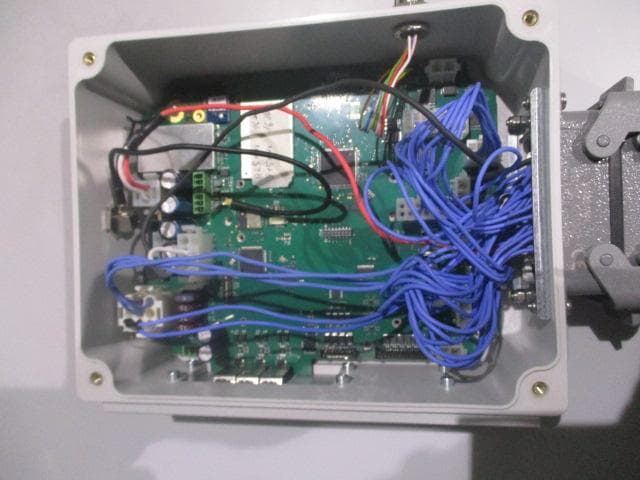
OQA-TM0N2EN0B3
Jul 20, 2026Transceiver Unit
Equipment Class
DSS - Part 15 Spread Spectrum Transmitter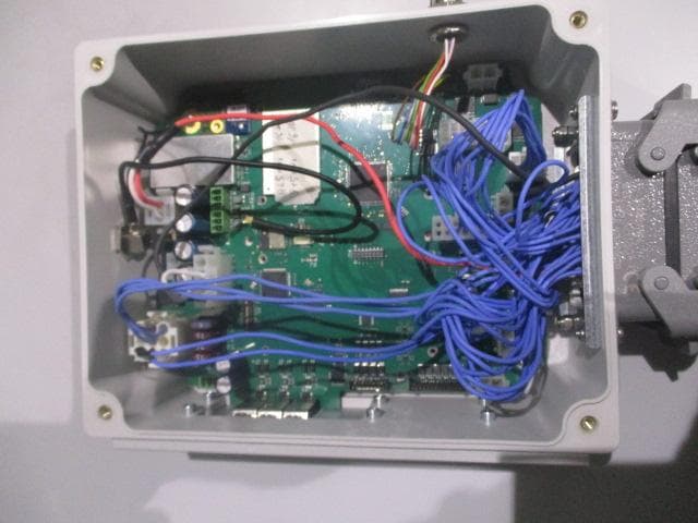
OQA-TX0N2BC0A3
Jul 09, 2026Transceiver unit
Equipment Class
DSS - Part 15 Spread Spectrum Transmitter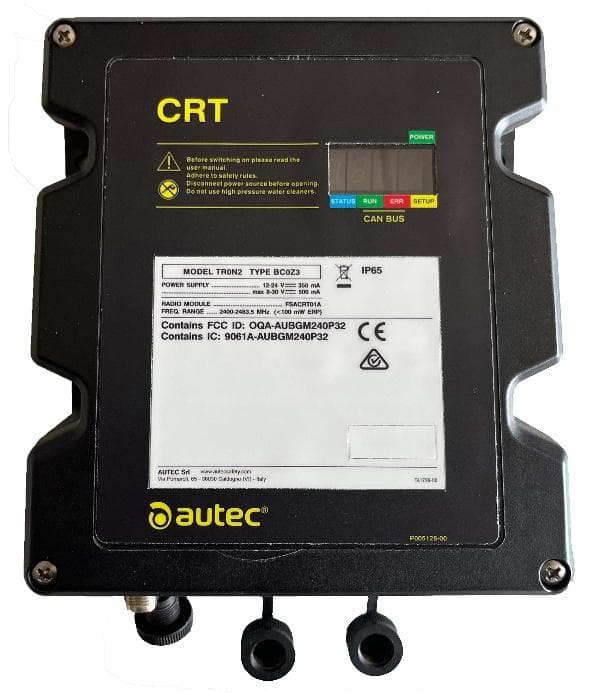
OQA-TR0N2BC0Z3
Jun 09, 2026Transceiver unit
Equipment Class
DSS - Part 15 Spread Spectrum Transmitter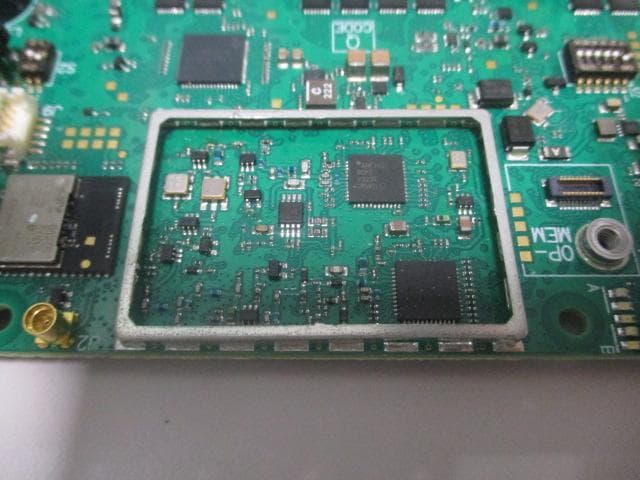
OQA-FSAACT01A
Mar 04, 2026Transceiver Unit
Equipment Class
DSS - Part 15 Spread Spectrum Transmitter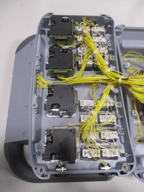
OQA-AX0A02Z0W1
Feb 24, 2026Transceiver Unit
Equipment Class
DSS - Part 15 Spread Spectrum Transmitter