OQA-E16STXUS1Part 15 Remote Control Transmitter
Autec s.r.l.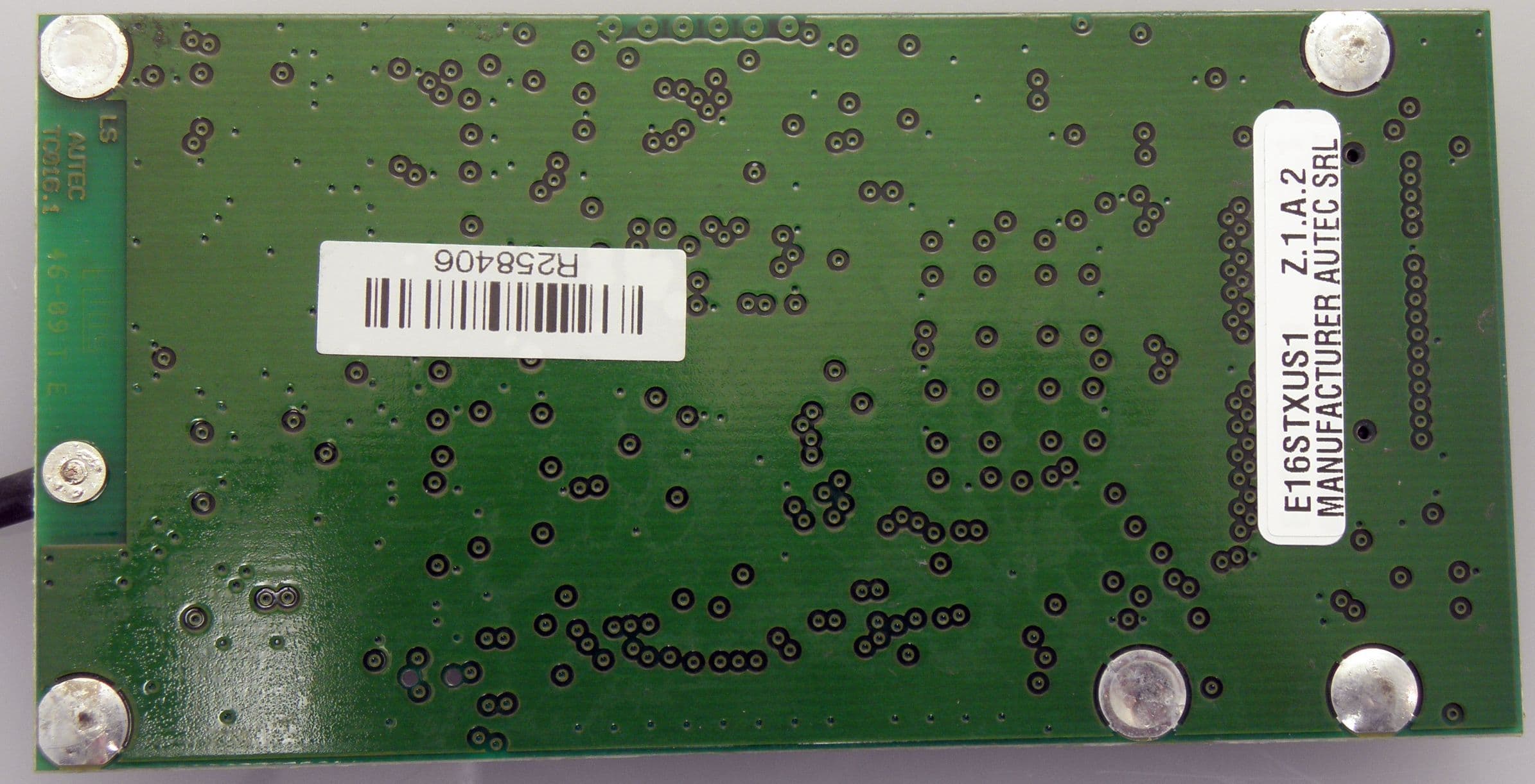
Click to zoom
Application Details
- Equipment Class
- DXX - Part 15 Low Power Communication Device Transmitter
- Date of Grant
- Apr 06, 2011
- Application Purpose
- Original Equipment
- Date of Application
- Apr 06, 2011
- Equipment Note
- Part 15 Remote Control Transmitter
- Frequency Range
- 902.15000000 - 927.72500000
- Company
- Autec s.r.l.
- Country
- Italy
Documents & Files
Document Text
Text extracted from the exhibit documents filed with the FCC. Open a document above to read the original.
Users Manual
1 E16STXUS1 guide E16STXUS1 guide 1Description 2Programming The transmitting module E16STXUS1 has two groups of DIP switches: a group of 4 and a group of 8 DIPs. They program some functions and set the working frequency. The Autec programming set in the other group of four dip switches must never be modified. The group of eight dip switches located on the radio module are used to program some func- tions and set the working frequency. A connector for interface card or keyboard Baddress key CDIP switches Dantenna DIPSTATEFUNCTION 1 ONThe transmitting unit never switches off automatically OFF If the transmitting unit stays switched on without any movement commands entered, it switches off after approx. 3.5 minutes 2 ONDeactivation of low battery warning from horn on machine OFFActivation of low battery warning from horn on machine 3 ON If DIP 8 is OFF automatic scan of the frequencies in the band 915 - 928 MHz OFF If DIP 8 is OFF automatic scan of the frequencies in the band 902 - 915 MHz 3-7 ON/OFFIf DIP 8 is ON see “Frequency Table” 8 ON Manual selection mode of the frequencies using DIP 3 - DIP 7 (refer to “Appendix: Frequency Table”) OFF Automatic scan mode of the frequencies in the band selected by DIP 3 (DIP 4 - DIP 7 indifferent) C A B D 2 E16STXUS1 guide In order to work correctly, the following DIP switches in the transmitting module E16STXUS1 and in the receiving module E16SRXUS1 of the radio remote control units must be set in the same way. 3Frequency table 4Antenna position The position of the E16STXUS1 antenna depends on the transmitting unit: the antenna can be folded to fit the space inside the transmitting unit but it must never be unsoldered from the module. 5Installation Autec maintains control of the assembly of the E61STXUS1 modules into the its transmitting units. It is forbidden any other type of use or installation by anyone. 6Replacement It is possible replace the E16STXUS1 transmitting module in the transmitting unit only by authorized personell which knows the procedure related to the specific transmitting unit. 7IC warning This device complies with Industry Canada licence-exempt RSS standard(s). Operation is sub- ject to the following two conditions: (1) this device may not cause interference, and (2) this device must accept any interference, including interference that may cause undesired operation of the device. MODULEDIP E16STXUS1 (group of 8 DIP switches) 2345678 E16SRXUS1 (group of 8 DIP switches) 2345678 3 E16STXUS1 guide 8 FCC warning This device complies with part 15 of the FCC Rules. Operation is subject to the following two conditions: (1) This device may not cause harmful interference, and (2) this device must accept any interference received, including interference that may cause undesired operation. Any changes or modifications to the software or equipment that are not expressly approved by Autec, could void the manufacturer’s warranty, and could void the user’s authority to oper- ate the equipment. 4 E16STXUS1 guide
Cover Letter(s)
1 FCC Limited Modular Approval declaration for E16STXUS1 transmitting module FCC Limited Modular Approval declaration for E16STXUS1 transmitting module This declaration is for FCC ID: OQA-E16STXUS1. 1Requirements in Section 15.212(a) rules n°Requirement 1 The radio elements must have the radio frequency circuitry shielded. Physical components and tuning capacitor(s) may be located external to the shield, but must be on the module assembly; (The shielding design must fully enfold the RF circuitry - that includes shielding the top, all sides and the bottom. The bottom may be a shielding ground plane and must be expressly designed as an effective shield made of materials such as sheet metal, metal mesh, or a metallic ink coated material) Compliance: TOP: 2 metallic shield mounted on PCB cover major RF Components. BOTTOM: ground plane (copper) on PCB 2 The module must have buffered modulation/data inputs to ensure that the device will comply with Part 15 requirements with any type of input signal Compliance: The module generates its own modulation data based on parallel inputs. The module has a data buffer before the parallel to serial conversion. Parallel to serial conversion is clocked internally. 3 The module must contain power supply regulation on the module. Compliance: Ye s 4 The module must contain a permanently attached antenna, or contain a unique antenna connector, and be marketed and operated only with specific antenna(s), per Sections 15.203, 15.204(b), 15.204(c), 15.212(a), 2.929(b)l Compliance: Yes, integrated antenna soldered to PCB 5 The module must demonstrate compliance in a stand-alone configuration. Compliance: Yes, see Test Report by Nemko Canada.
ID Label/Location Info
E16STXUS1 Label:
ID Label/Location Info
RADIO MODULE.............................................E16STXUS1 FREQUENCY RANGE....................................902-928MHz POWER SUPPLY................................MBM06MH 7,2V PROTECTION DEGREE..............................................IP65 TYPE TC02MODEL B04D Technical Data TA903/1 - A0TARG01P0665 ------ Contains FCC ID: OQA-E16STXUS1 Contains IC: 9061A-E16STXUS1 This radio device complies with Part 15 of the FCC Rules. Operation is subject to the following two conditions: (1) this device may not cause harmful interference, and (2) this device must accept any interference received, including interference that may cause undesired operation.
Operational Description
1 E16STXUS1 operational description E16STXUS1 operational description 1Description E16STXUS1is a radio transmitting module. A logic section collects commands coming from the various actuators (switches, pushbut- tons, joysticks ...) which are present in the unit where the module is used. E16STXUS1 module combines these command with an address code stored an EEPROM memory ("address Key"); a serial data telegram at 2200-2600 baud is so obtained. After a Gaussian spectrum shaping filter, the telegram is frequency modulated on a carrier generated by a PLL synthesizer and then trasmitted over a 25kHz channel in the 902-828 MHz band; 32 different frequencies my be chosen, so as to allow cohexistence of multiple units on the same location (for details see relative block diagrams). The module has an integrated antenna. However, it has also an coaxial connector which is used for factory testing only. Transmission is continuous (100% duty cycle) even with no command activated, since the receiver is expected to monitor continuously the presence of a valid radio signal. A receiving unit will decode only messages coming from a transmitter with the same address code. This excludes the possibility of an interference activating any function unwantedly. 2Technical data E16STXUS1 trasmitting radio module Used frequency band902.15 - 927.725 MHz Power supply 2.4 Vdc (<120 mA) or 7.2 Vdc (<35 mA) by Ni-MH Autec battery Type of modulation2200 - 2600 Baud GFSK Channel spacing25 kHz Designation of emission (ITU code)12K9F1D Strenght fieldsee relative Test Report Duty cycle up to 100 % (continuous duty), depends on user’s need Duplex directionsimplex Antenna type integrated λ/4 Antenna gain<2.15 dB Data telegram132 bit Hamming distance> 8 Probability of non-recognition of error<10 exp-11 2 E16STXUS1 operational description
Test Report
www.nemko.com Report Reference ID: 168216-1TRFWL Test specification: Title 47 - Telecommunication Chapter I - Federal Communications Commission Subchapter A - General Part 15 - Radio Frequency Devices Subpart C - Intentional Radiators − §15.249 - Operation in the 902–928 MHz, 2400–2483.5 MHz, 5725–5875 MHz and 24.0–24.25 GHz Applicant: Autec s.r.l. Via Pomaroli, 65 Caldogno VI, 36030 Italy Apparatus: Transmitter module FCC ID: OQA-E16STXUS1 Model: E16STXUS1 Testing laboratory: Nemko Canada Inc. 303 River Road Ottawa, ON, Canada K1V 1H2 Telephone: (613) 737-9680 Facsimile: (613) 737-9691 Name and title Date Tested by: Andrey Adelberg, Wireless/EMC Specialist March 16, 2011 Reviewed by: David Duchesne, Wireless/EMC Specialist March 31, 2011 Nemko Canada Inc., a testing laboratory, is accredited by the Standards Council of Canada. The tests included in this report are within the scope of this accreditation. 15.231.doc - Date: April 13, 2010 Product: Transmitter module Nemko Canada Inc., 303 River Rd, Ottawa, ON, Canada, K1V 1H2 Report reference ID: 168216-1TRFWL Page 2 of 23 Table of contents Section 1: Report summary.........................................................................................................................................................3 1.1 Test specification.........................................................................................................................................................3 1.2 Statement of compliance.............................................................................................................................................3 1.3 Exclusions....................................................................................................................................................................3 1.4 Registration number....................................................................................................................................................3 1.5 Test report revision history...........................................................................................................................................3 1.6 Limits of responsibility..................................................................................................................................................3 Section 2: Summary of test results.............................................................................................................................................4 2.1 FCC Part 15 Subpart C – Intentional Radiators, test results........................................................................................4 Section 3: Equipment under test (EUT) and application details...............................................................................................5 3.1 Applicant details...........................................................................................................................................................5 3.2 Sample information......................................................................................................................................................5 3.3 EUT technical specifications........................................................................................................................................5 3.4 Operation of the EUT during testing............................................................................................................................5 3.5 EUT setup diagram......................................................................................................................................................5 Section 4: Engineering considerations.......................................................................................................................................6 4.1 Modifications incorporated in the EUT.........................................................................................................................6 4.2 Deviations from laboratory tests procedures................................................................................................................6 4.3 Technical judgment......................................................................................................................................................6 Section 5: Test conditions...........................................................................................................................................................7 5.1 Power source and ambient temperatures....................................................................................................................7 Section 6: Measurement uncertainty..........................................................................................................................................8 Section 7: Test equipment...........................................................................................................................................................9 7.1 Test equipment list.......................................................................................................................................................9 Section 8: Testing data...............................................................................................................................................................10 8.1 Clause 15.31(e) Variation of power source................................................................................................................10 8.2 Clause 15.31(m) Number of operating frequencies...................................................................................................11 8.3 Clause 15.203 Antenna requirement.........................................................................................................................12 8.4 Clause 15.215(c) Emission bandwidth.......................................................................…
Text truncated - open the document above for the full version.
Contact Information
Applicant
Antonio Silvestri(Director)
Technical Contact
Non-Technical Contact
Autec srlSilvia Bertuzzo
[email protected]+39 0444 901012
Test Firm
Nemko Canada Inc. (Ottawa)Charles Neal
Technical Specifications
| # | Rule Parts | Frequency Range | Power Output |
|---|---|---|---|
| 1 | 15C | 902.15 MHz - 927.725 MHz | - |
Other Applications from Autec s.r.l.
OQA-TM0N2EN0B3
Jul 20, 2026Transceiver Unit
Equipment Class
DSS - Part 15 Spread Spectrum Transmitter
OQA-TX0N2BC0A3
Jul 09, 2026Transceiver unit
Equipment Class
DSS - Part 15 Spread Spectrum Transmitter
OQA-TR0N2BC0Z3
Jun 09, 2026Transceiver unit
Equipment Class
DSS - Part 15 Spread Spectrum Transmitter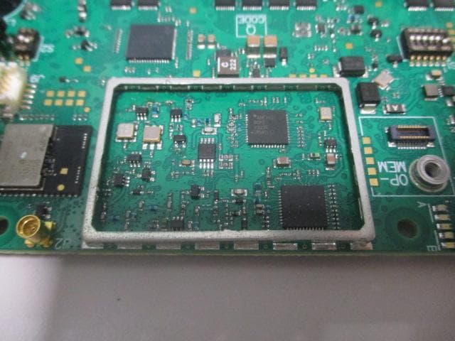
OQA-FSAACT01A
Mar 04, 2026Transceiver Unit
Equipment Class
DSS - Part 15 Spread Spectrum Transmitter
OQA-AX0A02Z0W1
Feb 24, 2026Transceiver Unit
Equipment Class
DSS - Part 15 Spread Spectrum Transmitter