OQA-LKNDA1DMTransceiver unit
Autec s.r.l.
Click to zoom
Application Details
- Equipment Class
- DXT - Part 15 Low Power Transceiver, Rx Verified
- Date of Grant
- Oct 04, 2015
- Application Purpose
- Original Equipment
- Date of Application
- Oct 04, 2015
- Equipment Note
- Transceiver unit
- Frequency Range
- 915.05000000 - 927.75000000
- Company
- Autec s.r.l.
- Country
- Italy
Documents & Files
Document Text
Text extracted from the exhibit documents filed with the FCC. Open a document above to read the original.
Users Manual
Original instructions Air series User manual Description, warnings and instructions LIAIRE02-02 AUTECLIAIRE02-02 Warnings and caption for the documentation attached to the radio remote control The attached documentation is an integral part of the radio remote control and it aims at providing the instructions needed for using and maintaining the system, paying particular attention to the safety functions. Always remember that: -photos and drawings are useful examples that help understand the instructions and warnings of each radio remote control configuration -if necessary, contact Autec if any of the instructions and/or warnings are not clear. No part of the documentation may be reproduced, in any form or by any means, without written permission of Autec (including recording and photocopying). If documentation is lost or damaged, ask Autec for a copy. Please specify the serial number of the related radio remote control. The documentation must be kept for the whole life of the radio remote control: after reading it, keep it on hand for future reference. All installation, usage and maintenance operations must be carried out by qualified technicians who are suitably trained with respect to the relevant norms and laws. Information contained in the radio remote control documentation adds to and completes the information provided by the manufacturer of the remote controlled machine and/or by those who install the radio remote control on the machine. Therefore, this documentation must be read and understood in all its parts by the user and by: -the radio remote control owner and/or installer -the person responsible for and in charge of maintenance and/or safety in the workplace where the radio remote control is used. As for instructions and warnings regarding the machine where the radio remote control is installed, follow the instructions given in the machine's manual. LIAIRE02-02AUTEC Three symbols are employed throughout documentation, which are used to highlight specific safety-related issues. They are classified according to the hazardous situation that may arise and on the possible consequences: Symbol If the highlighted instructions are not respected ... ... a dangerous situation will occur... ...consequences for people may be... ...consequences for property may be... ...highly probable. ... critical (death or physical damage). ... critical. ... probable. ... critical (death or physical damage). ... critical. ... probable. ... moderate (non-severe physical damage). ... moderate. This symbol is also used, and it identifies texts to be read carefully. AUTECLIAIRE02-02 AI r SerIeS Part A: Description, warnings and instructions InDex 1 radio remote control description ........................................................................ 6 1.1 How the radio remote control works ................................................................. 6 1.2 Technical Data ................................................................................................. 6 1.3 Applications ..................................................................................................... 6 1.4 Radio link ......................................................................................................... 7 1.5 Classification of commands ............................................................................. 7 1.6 Safety function: stop protection ........................................................................ 7 1.7 Protection against unintended movements from the rest position ..................... 8 1.8 Identifying the radio remote control .................................................................. 8 2 risk assessment ................................................................................................... 9 2.1 Risk assessment for radio remote controlled machines .................................... 9 2.2 Staff training .................................................................................................. 10 2.3 Working conditions ........................................................................................ 10 3 Warnings for installation .................................................................................... 11 3.1 General .......................................................................................................... 11 3.2 Mounting and fastening the receiving unit in the best position ........................ 11 3.3 Positioning the antenna ................................................................................. 12 3.4 Wiring ............................................................................................................ 12 3.5 At end of installation ...................................................................................... 15 3.6 Testing ........................................................................................................... 15 4 Warnings for use ................................................................................................. 16 4.1 Before starting to work ................................................................................... 16 4.2 During normal operation ................................................................................ 17 4.3 After using the radio remote control ............................................................... 17 5 radio remote control life cycle .......................................................................... 18 5.1 Transportation and storage ............................................................................ 18 5.2 Installation ..................................................................................................... 18 5.3 Use ................................................................................................................ 19 5.4 Radio remote control maintenance ................................................................. 19 5.5 Machine maintenance ....…
Text truncated - open the document above for the full version.
Users Manual
Original instructions Air series Part B: Conformity and frequencies (434 and 915MHz) index 1 Conformity ............................................................................................................. 2 1.1 Conformity of frequency band 433.050-434.790MHz ........................................ 2 1.2 Conformity of frequency band 915-928MHz: FCC and IC ................................. 2 2 Frequencies ........................................................................................................... 3 2.1 Frequency band 433.050-434.790MHz ............................................................ 4 2.2 Frequency band 915-928MHz .......................................................................... 4 AUTECLIAIRE12-01 2 LIAIRE12-01 Conformity AUTEC - Air series 1 Conformity 1.1 Conformity of frequency band 433.050-434.790MHz Each AIR series' radio remote control working in the frequency band 433.050-434.790MHz complies with the (R&TTE) Directive 1999/5/EC and its essential requirements. Each radio remote control is also in conformity with the harmonised standards provided in the EC Declaration of Conformity. You can find the EC Declaration of Conformity on the website www.autecsafety.com, in the product page of the relevant transmitting unit. 1.2 Conformity of frequency band 915-928MHz: FCC and iC An AIR series' radio remote control working in the frequency band 915-928MHz complies with the essential requirements of the following regulations: -FCC (Federal Communication Commission) Part 15 -IC (Industry Canada) RSS-102 UnitFCC idiC number A8 transmitting unitOQA-A08LA0AM9061A-A08LA0AM AJM transmitting unitOQA-AJMDA0BM9061A-AJMDA0BM AJr transmitting unitOQA-AJRDA0BM9061A-AJRDA0BM AJs transmitting unitOQA-AJSDA0BM9061A-AJSDA0BM Transmitting unit LK6/LK8 OQA-LKNLA1CM9061A-LKNLA1CM Transmitting unit LK6 dF OQA-LKNDA1DM9061A-LKNDA1DM receiving unit G ACrs13-G OQA-RGAGA00M d 9061A-RGAGA00M a b c receiving unit G dCrs13 OQA-RGEBA00M d 9061A-RGEBA00M a b c receiving unit L ACrs13-L OQA-RLBHA00M d 9061A-RLBCA00M a b c receiving unit M ACrM15 OQA-RMCEA00M d 9061A-RMCEA00M a b c receiving unit HACrP8 OQA-RPDFA00M d 9061A-RPDFA00M a b c receiving unit MVrCAn OQA-RNFLA00M d 9061A-RNFLA00M a b c receiving unit MVrL9e OQA-RRLPA00M d 9061A-RRLPA00M a b c AUTEC - Air series Frequencies3 LIAIRE12-01 receiving unit dCrM24 OQA-RMGMA00M d 9061A-RMGMA00M a b c receiving unit ACrM5e OQA-RMHN00M d 9061A-RMHNA00M a b c a. Under Industry Canada regulations, this radio transmitter may only operate using an antenna of a type and maximum (or lesser) gain approved for the transmitter by Industry Canada. To reduce potential radio interference to other users, the antenna type and its gain should be so chosen that the equivalent isotropically radiated power (e.i.r.p.) is not more than that necessary for successful communication. b. This radio transmitter has been approved by Industry Canada to operate with the antenna types listed below with the maximum permissible gain and required antenna impedance for each antenna type indicated. Antenna types not included in this list, having a gain greater than the maximum gain indicated for that type, are strictly prohibited for use with this device. Antenna typeAntenna gainAntenna impedance Autec stylus λ/4<0dBi50 Ohm c. Autec allows you to use only the dedicated antenna supplied either with the remote control or as original spare part. The use of any other type of antenna is prohibited and will invalidate the guarantee. d. Place the antenna of the receiving unit in a position that ensures a minimum separation distance of 20cm with all the people that can be in the working area. 1.2.1 Federal Communications Commission (FCC) This device complies with part 15 of the FCC Rules. Operation is subject to the following two conditions: (1) this device may not cause harmful interference, and (2) this device must accept any interference received, including interference that may cause undesired operation. Any changes or modifications not expressly approved by the party responsible for compliance could void the user’s authority to operate the equipment. 1.2.2 industry Canada (iC) This device complies with RSS-210 of the Industry Canada Rules. Operation is subject to the following two conditions: (1) this device may not cause harmful interference, and (2) this device must accept any interference received, including interference that may cause undesired operation. 2 Frequencies AIR series radio remote controls can work at two different frequency bands: 433.050- 434.790MHz or 915.000-928.000MHz. 4 LIAIRE12-01 Frequencies AUTEC - Air series The radio remote controls' working frequency is defined by market-specific laws and standards. in order for the system “machine+radio remote control” to be compliant and therefore to be used, it shall comply with such laws and standards: if it does not, the system may be impounded by competent bodies. Autec cannot be held responsible if the radio remote control is set with forbidden frequencies. They automatically search for a free working frequency. 2.1 Frequency band 433.050-434.790MHz 2.1.1 Frequencies The radio link between the units of Autec AIR series radio remote controls is established at one of the frequencies permitted by the European standards in force when the system is put on the market. Frequencies used in the band 433.050-434.790MHz ..................................................... 64 RF power ................................................................................................................ <1mW Channel spacing ...................................................................................................... 25kHz 2.1.2 Market Air series' radio remote controls working in the frequency band 433.050-434.790 MHz can be used within the EU (European Union), the EFTA (European Free Trade Association), in Australia and in Singapore. 2.2 Frequency band 915-928MHz 2.2.1 Frequencies The radio link between the…
Text truncated - open the document above for the full version.
Users Manual
Traduction de la notice d'origine Série Air Manuel de l'utilisateur Description, avertissements et instructions LIAIRF02-02 AUTECLIAIRF02-02 Avertissements et légende de la documentation jointe à la radiocommande Toute la documentation jointe fait partie intégrante de la radiocommande et a pour objectif de fournir les indications nécessaires à l'utilisation et à l'entretien, avec une attention particulière portée sur les fonctions de sécurité. Il est rappelé que : -les photos et les plans sont fournis à titre indicatif afin de mieux comprendre les instructions et les avertissements de chaque configuration de la radiocommande, -contacter Autec en cas de doute sur les instructions et/ou les consignes. Aucune partie de la documentation ne peut, sous aucun prétexte, être reproduite quel que soit le format ou le moyen, sans autorisation écrite d'Autec (y compris l'enregistrement et la photocopie). En cas de détérioration ou de perte de la documentation, en demander une copie à Autec en spécifiant le numéro de série de la radiocommande correspondante. Il est rappelé que toute la documentation doit être conservée sur toute la durée de vie de la radiocommande : après l'avoir lue, la tenir à disposition pour toute consultation. Toutes les opérations d'installation, d'utilisation et d'entretien doivent obligatoirement être exécutées par un personnel qualifié et formé aux réglementations et aux lois de référence. Les informations reportées dans la documentation de la radiocommande sont complémentaires à celles fournies par le constructeur de la machine équipée de la radiocommande et/ou par l'installateur de la radiocommande sur la machine. Ainsi, faut-il que la présente documentation ait été lue et comprise entièrement non seulement par l'opérateur mais également par : -le propriétaire et/ou l’installateur de la radiocommande, -le responsable et l'opérateur chargé de l'entretien et/ou de la sécurité sur le lieu de travail où la radiocommande est utilisée. Pour les instructions et les avertissements relatifs à la machine équipée d'une radiocommande, suivre les indications du constructeur reportées dans le manuel d'instructions de la machine. LIAIRF02-02AUTEC La documentation utilise trois symboles mettant en évidence des indications particulières relatives à la sécurité en fonction de la situation à risque générée, ainsi que les conséquences : Symbole L'inobservation des indications mises en évidence... ... porte à une situation de danger ... ... peut porter atteinte aux personnes ... ... peut détériorer les biens ... ...certaine. ... graves (mort ou dommages physiques). ... graves. ... probable. ... graves (mort ou dommages physiques). ... graves. ... probable. ... modérées (dommages physiques légers). ... modérées. Par ailleurs, ce symbole met en évidence les textes à lire avec une attention particulière. AUTECLIAIRF02-02 Série Air Partie A : Description, avertissements et instructions SommAire 1 Description de la radiocommande ....................................................................... 6 1.1 Fonctionnement de la radiocommande ............................................................ 6 1.2 Données techniques ........................................................................................ 6 1.3 Applications ..................................................................................................... 6 1.4 Liaison radioélectrique ..................................................................................... 7 1.5 Classification des commandes ......................................................................... 7 1.6 Fonction de sécurité : protection de l'arrêt ....................................................... 7 1.7 Protection contre les mouvements involontaires à partir de la position de repos 8 1.8 Identification de la radiocommande .................................................................. 8 2 évaluation des risques ......................................................................................... 9 2.1 Évaluation des risques pour les machines radiocommandées .......................... 9 2.2 Formation du personnel ................................................................................. 10 2.3 Conditions de travail ...................................................................................... 10 3 Consignes d’installation ..................................................................................... 11 3.1 Générales ...................................................................................................... 11 3.2 Positionnement et fixation de l'unité de réception ........................................... 11 3.3 Positionnement de l'antenne .......................................................................... 12 3.4 Câblage ......................................................................................................... 12 3.5 Au terme de l’installation ................................................................................ 15 3.6 Réception ...................................................................................................... 15 4 Consignes d'utilisation ....................................................................................... 16 4.1 Avant de commencer à travailler .................................................................... 16 4.2 Lors du fonctionnement courant ..................................................................... 17 4.3 Après avoir utilisé la radiocommande ............................................................. 17 5 Cycle de vie de la radiocommande .................................................................... 18 5.1 Transport et stockage .................................................................................... 18 5.2 Installation ..................................................................................................... 18 5.3 Utilisation ......................................................…
Text truncated - open the document above for the full version.
Users Manual
Traduction de la notice d'origine Série Air Partie B: Conformité et fréquences (434 et 915MHz) SoMMAire 1 Conformité ............................................................................................................. 2 1.1 Conformité de la bande de fréquence 433.050-434.790MHz ............................ 2 1.2 Conformité de la bande de fréquence 915-928MHz: FCC et IC ........................ 2 2 Fréquences ............................................................................................................ 3 2.1 Bande de fréquence 433.050-434.790MHz ...................................................... 4 2.2 Bande de fréquence 915-928MHz .................................................................... 4 AUTECLIAIRF12-01 2 LIAIRF12-01 Conformité AUTEC - Série Air 1 Conformité 1.1 Conformité de la bande de fréquence 433.050-434.790MHz Chaque radiocommande de la série AIR opérant sur la bande de fréquence 433.050- 434.790MHz est conforme à la directive 1999/5/CE (R&TTE) et à ses exigences nécessaires. Chaque radiocommande est, par ailleurs, conforme aux normes harmonisées reportées sur la déclaration de conformité CE. La déclaration de conformité CE se trouve sur le site internet www.autecsafety.com, à la page Produit de l'unité de transmission correspondante. 1.2 Conformité de la bande de fréquence 915-928MHz: FCC et iC Une radiocommande de la série AIR opérant sur la bande de fréquence 915-928MHz est conforme aux exigences nécessaires : -FCC (Federal Communication Commission) Part 15 -IC (Industry Canada) RSS-102 UnitéFCC iDiC Number Unité de transmission A8OQA-A08LA0AM9061A-A08LA0AM Unité de transmission AJMOQA-AJMDA0BM9061A-AJMDA0BM Unité de transmission AJrOQA-AJRDA0BM9061A-AJRDA0BM Unité de transmission AJSOQA-AJSDA0BM9061A-AJSDA0BM Unité de transmission LK6/LK8 OQA-LKNLA1CM9061A-LKNLA1CM Unité de transmission LK6 DF OQA-LKNDA1DM9061A-LKNDA1DM Unité de réception G ACrS13-G OQA-RGAGA00M d 9061A-RGAGA00M a b c Unité de réception G DCrS13 OQA-RGEBA00M d 9061A-RGEBA00M a b c Unité de réception L ACrS13-L OQA-RLBHA00M d 9061A-RLBCA00M a b c Unité de réception M ACrM15 OQA-RMCEA00M d 9061A-RMCEA00M a b c Unité de réception HACrP8 OQA-RPDFA00M d 9061A-RPDFA00M a b c Unité de réception MVrCAN OQA-RNFLA00M d 9061A-RNFLA00M a b c Unité de réception MVrL9e OQA-RRLPA00M d 9061A-RRLPA00M a b c AUTEC - Série Air Fréquences3 LIAIRF12-01 Unité de réception DCrM24 OQA-RMGMA00M d 9061A-RMGMA00M a b c Unité de réception ACrM5e OQA-RMHN00M d 9061A-RMHNA00M a b c a. Conformément à la réglementation d'Industrie Canada, le présent émetteur radio peut fonctionner avec une antenne d'un type et d'un gain maximal (ou inférieur) approuvé pour l'émetteur par Industrie Canada.Dans le but de réduire les risques de brouillage radioélectrique à l'intention des autres utilisateurs, il faut choisir le type d'antenne et son gain de sorte que la puissance isotrope rayonnée équivalente (p.i.r.e.) ne dépasse pas l'intensité nécessaire à l'établissement d'une communication satisfaisante. b. Le présent émetteur radio a été approuvé par Industrie Canada pour fonctionner avec les types d'antenne énumérés ci-dessous et ayant un gain admissible maximal et l'impédance requise pour chaque type d'antenne.Les types d'antenne non inclus dans cette liste, ou dont le gain est supérieur au gain maximal indiqué, sont strictement interdits pour l'exploitation de l'émetteur. Type d'antenneGain d'antenneimpédance de l'antenne Autec stylus λ/4<0dBi50 Ohm c. Autec vous autorise seulement à utiliser l'antenne dédiée fournie avec la radiocommande ou comme pièce de rechange d'origine. L'utilisation de tout autre type d'antenne est interdite et annulerait la garantie. d. Placez l'antenne de l'unité de réception dans une position qui permet de garantir au moins une distance minimale de 20 cm avec toutes les personnes qui peuvent être dans la zone de travail. 1.2.1 Federal Communications Commission (FCC) This device complies with part 15 of the FCC Rules. Operation is subject to the following two conditions: (1) this device may not cause harmful interference, and (2) this device must accept any interference received, including interference that may cause undesired operation. Any changes or modifications not expressly approved by the party responsible for compliance could void the user’s authority to operate the equipment. 1.2.2 industry Canada (iC) Ce dispositif est conforme à la norme CNR-210 d'Industrie Canada applicable aux appareils radio exempts de licence. Son fonctionnement est sujet aux deux conditions suivantes: (1) le dispositif ne doit pas produire de brouillage préjudiciable, et (2) ce dispositif doit accepter tout brouillage reçu, y compris un brouillage susceptible de provoquer un fonctionnement indésirable. 2 Fréquences Les radiocommandes de la série AIR peuvent travailler sur deux bandes de fréquences distinctes: 433.050-434.790MHz ou 915.000-928.000MHz. 4 LIAIRF12-01 Fréquences AUTEC - Série Air La fréquence à laquelle une radiocommande peut opérer est imposée par les lois et les réglementations en fonction du marché d'utilisation. Afin que le système « machine + radiocommande » s'avère conforme et puisse ainsi être utilisé, ces lois et ces réglementations doivent être respectées. Dans le cas contraire, le système risquerait d'être mis sous séquestre par les organismes compétents. Autec ne pourra assumer aucune responsabilité si la radiocommande est configurée avec une fréquence non autorisée. La recherche d'une fréquence libre s'effectue automatiquement. 2.1 Bande de fréquence 433.050-434.790MHz 2.1.1 Fréquences La liaison radioélectrique entre les unités des radiocommandes Autec de la série AIR s'effectue avec l'une des fréquences autorisées par les réglementations européennes en vigueur lors de leur introduction sur le marché. Fréquences utilisées sur la bande 433.050-434.790 MHz .............................................. 64 Puissance RF .................................................................…
Text truncated - open the document above for the full version.
Users Manual
Original instructions Air series Part C: LK6, LK8 and LK6 DF transmitting units inDex 1 Description ............................................................................................................ 3 1.1 Description of units LK6 and LK8 ..................................................................... 3 1.2 Description of unit LK6 DF ............................................................................... 4 2 Technical data ....................................................................................................... 5 2.1 Technical data of units LK6 and LK8 ................................................................ 5 2.2 Technical data of unit LK6 DF .......................................................................... 5 3 Technical data sheet ............................................................................................. 5 4 Plates ..................................................................................................................... 6 4.1 Plates on units LK6, LK8 and LK6 DF belonging to a radio remote control system ............................................................................................................. 6 4.2 Plates on units LK6, LK8 and LK6 DF belonging to a Take & Release system . 6 4.3 Plates on units LK6, LK8 and LK6 DF belonging to a Multi Units or Multi Receiver system ............................................................................................................. 7 5 Light signals .......................................................................................................... 8 5.1 Light signals of units LK6 and LK8 ................................................................... 8 5.2 Light signals of unit LK6 DF ........................................................................... 10 6 General operating instructions .......................................................................... 13 6.1 Starting up the radio remote control ............................................................... 13 6.2 Command activation ...................................................................................... 15 6.3 Data Feedback Function ................................................................................ 15 6.4 Radio link interruption .................................................................................... 16 AUTECLILK6E00-02 LILK6E00-02AUTEC 6.5 Transmitting unit automatic switch off ............................................................ 16 6.6 Switching off the transmitting unit ................................................................... 16 7 Operation ............................................................................................................. 17 7.1 Battery ........................................................................................................... 17 7.2 ID internal tx memory ..................................................................................... 18 7.3 Power keyswitch ............................................................................................ 18 7.4 START pushbutton ........................................................................................ 20 7.5 FUNCTION pushbutton .................................................................................. 20 7.6 STOP pushbutton .......................................................................................... 20 7.7 DISPLAY pushbutton (if the transmitting unit has a display) ........................... 20 8 Malfunction signalled by the transmitting unit ................................................. 21 AUTEC - Air series Description3 LILK6E00-02 1 Description 1.1 Description of units LK6 and LK8 L K J H G F E D C B M A N P ALED B Actuator (selector, pushbutton) (if present) CBattery DPower keyswitch (if present) eBattery housing FTransmitting unit identification plate GRadio remote control identification plate HTechnical data plate JSTART pushbutton KFUNCTION pushbutton LCommand pushbuttons MSTOP pushbutton nDIP switches PConnector for "ID internal tx memory" 4 LILK6E00-02 Description AUTEC - Air series 1.2 Description of unit LK6 DF M L K J H F E D C B N A G P Q ADisplay B Actuator (selector, pushbutton) (if present) CBattery DPower keyswitch (if present) eBattery housing FTransmitting unit identification plate GDISPLAY pushbutton HRadio remote control identification plate JTechnical data plate KSTART pushbutton LFUNCTION pushbutton MCommand pushbuttons nSTOP pushbutton PDIP switches QConnector for "ID internal tx memory" AUTEC - Air series Technical data5 LILK6E00-02 2 Technical data 2.1 Technical data of units LK6 and LK8 Power supply (battery MHM03) .............................................................................. 3.6V Power supply (battery LPM01) ............................................................................... 3.7V Antenna .................................................................................................................. internal Housing material .......................................................................................... PA 6 (20%fg) Protection degree ....................................................................................... IP65 (NEMA 4) Dimensions .................................................................. 201x85x49mm (7.91x3.35x1.92In) Weight ....................................................................................................... 380g (0.837Lb) Run time at 20°C (68°F): - with battery MHM03 ....................................................................................................>8h - with battery LPM01 ...................................................................................................>16h 2.2 Technical data of unit LK6 DF Power supply (battery LPM01) ............................................................................... 3.7V Antenna ...................…
Text truncated - open the document above for the full version.
Contact Information
Applicant
Antonio Silvestri(Director)
Test Firm
CMC Centro Misure Compatibilit� srlBeghetto Renzo
Technical Specifications
| # | Rule Parts | Frequency Range | Power Output |
|---|---|---|---|
| 1 | 15C | 915.05 MHz - 927.75 MHz | - |
Other Applications from Autec s.r.l.
OQA-TM0N2EN0B3
Jul 20, 2026Transceiver Unit
Equipment Class
DSS - Part 15 Spread Spectrum Transmitter
OQA-TX0N2BC0A3
Jul 09, 2026Transceiver unit
Equipment Class
DSS - Part 15 Spread Spectrum Transmitter
OQA-TR0N2BC0Z3
Jun 09, 2026Transceiver unit
Equipment Class
DSS - Part 15 Spread Spectrum Transmitter
OQA-FSAACT01A
Mar 04, 2026Transceiver Unit
Equipment Class
DSS - Part 15 Spread Spectrum Transmitter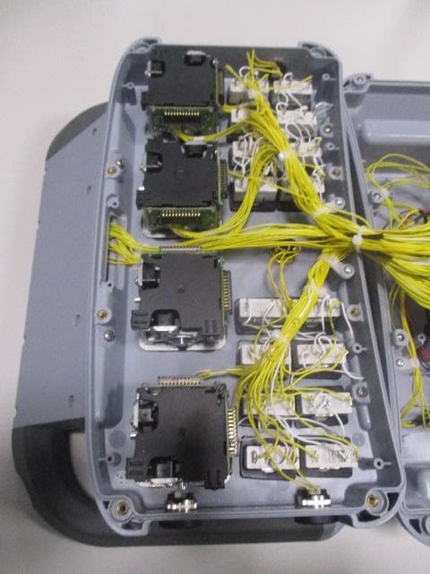
OQA-AX0A02Z0W1
Feb 24, 2026Transceiver Unit
Equipment Class
DSS - Part 15 Spread Spectrum Transmitter