OQA-PCRNKZ22Transceiver unit
Autec s.r.l.
Click to zoom
Application Details
- Equipment Class
- DSS - Part 15 Spread Spectrum Transmitter
- Date of Grant
- Mar 26, 2015
- Application Purpose
- Original Equipment
- Date of Application
- Mar 26, 2015
- Equipment Note
- Transceiver unit
- Frequency Range
- 915.05000000 - 927.95000000
- Company
- Autec s.r.l.
- Country
- Italy
Documents & Files
Document Text
Text extracted from the exhibit documents filed with the FCC. Open a document above to read the original.
Users Manual
Original instructions Dynamic SerieS Part B: conformity and frequencies (915mHz - Fcc/ic) inDex 1 conformity ............................................................................................................. 2 1.1 Federal Communications Commission (FCC) ................................................... 3 1.2 Industry Canada (IC) ........................................................................................ 3 2 Frequencies ........................................................................................................... 3 2.1 Dynamic mode ................................................................................................. 3 2.2 Static mode ...................................................................................................... 3 3 market .................................................................................................................... 4 AUTECLIDY2E00-07 2 LIDY2E00-07 Conformity AUTEC - Dynamic Series 1 conformity Each Dynamic series' radio remote control working in the frequency band 915-928MHz complies with Part 15 of standards FCC and with RSS-210 of IC standards. UnitFcc iDic number aDDOQA-ADDNE022 d 9061A-ADDNE022 a b c arm OQA-ARMNB022 d OQA-ARMNC022 d 9061A-ARMNB022 a b c 9061A-ARMNC022 a b c arSOQA-ARSND022 d 9061A-ARSND022 a b c arxOQA-ARXNG022 d 9061A-ARXNG022 a b c crSOQA-CRSNA022 d 9061A-CRSNA022 a b c FJLOQA-FJLNF0229061A-FJLNF022 FJmOQA-FJMNF0229061A-FJMNF022 FJrOQA-FJRNF0229061A-FJRNF022 FJSOQA-FJSNF0229061A-FJSNF022 PcrOQA-PCRNKZ22 d / a. Under Industry Canada regulations, this radio transmitter may only operate using an antenna of a type and maximum (or lesser) gain approved for the transmitter by Industry Canada. To reduce potential radio interference to other users, the antenna type and its gain should be so chosen that the equivalent isotropically radiated power (e.i.r.p.) is not more than that necessary for successful communication. b. This radio transmitter has been approved by Industry Canada to operate with the antenna types listed below with the maximum permissible gain and required antenna impedance for each antenna type indicated. Antenna types not included in this list, having a gain greater than the maximum gain indicated for that type, are strictly prohibited for use with this device. antenna typeantenna gainantenna impedance Autec stylus λ/4<2dBi50 Ohm Autec stylus λ/4 with 5m rG58 <2dBi50 Ohm c. Autec allows you to use only the dedicated antenna supplied either with the remote control or as original spare part. The use of any other type of antenna is prohibited and will invalidate the guarantee. d. Place the antenna of the receiving unit in a position that ensures a minimum separation distance of 20cm with all the people that can be in the working area. AUTEC - Dynamic Series Frequencies3 LIDY2E00-07 1.1 Federal communications commission (Fcc) This device complies with part 15 of the FCC Rules. Operation is subject to the following two conditions: (1) this device may not cause harmful interference, and (2) this device must accept any interference received, including interference that may cause undesired operation. Any changes or modifications not expressly approved by the party responsible for compliance could void the user’s authority to operate the equipment. 1.2 industry canada (ic) This device complies with RSS-210 of the Industry Canada Rules. Operation is subject to the following two conditions: (1) this device may not cause harmful interference, and (2) this device must accept any interference received, including interference that may cause undesired operation. 2 Frequencies The radio link between the units of Autec Dynamic series radio remote controls is built at one of the frequencies permitted by the US, Canadian and Australian standards in force when the system is put on the market. Frequency band ............................................................................................ 915-928MHz RF power ........................................................................ meets FCC and IC requirements Available radio channels .............................................................................................. 259 Channel spacing ...................................................................................................... 50kHz Dynamic series industrial radio remote controls communicate either in dynamic or static mode. Mode is set by the machine manufacturer. 2.1 Dynamic mode A radio remote control communicating in dynamic mode: -uses a working frequency in the band 915-928MHz -checks that the frequency is free before using it -continually changes the working frequency to maintain the radio link even when interference occurs. 2.2 Static mode A radio remote control communicating in static mode: -uses a working frequency in the band 915-928MHz -checks that the frequency is free before using it -always works at the same frequency until the stop function is activated. 4 LIDY2E00-07 Market AUTEC - Dynamic Series 3 market Dynamic series' radio remote controls working in the frequency band 915-928MHz can be used in the US, Canadian and Australian markets.
Users Manual
Original instructions Dynamic series User manual Description, warnings and instructions LIDYNE00-05 AUTECLIDYNE00-05 Warnings and caption for the documentation attached to the radio remote control The attached documentation is an integral part of the radio remote control and it aims at providing the instructions needed for using and maintaining the system, paying particular attention to the safety functions. Always remember that: -photos and drawings are useful examples that help understand the instructions and warnings of each radio remote control configuration -if necessary, contact Autec if any of the instructions and/or warnings are not clear. No part of the documentation may be reproduced, in any form or by any means, without written permission of Autec (including recording and photocopying). If documentation is lost or damaged, ask Autec for a copy. Please specify the serial number of the related radio remote control. The documentation must be kept for the whole life of the radio remote control: after reading it, keep it on hand for future reference. All installation, usage and maintenance operations must be carried out by qualified technicians who are suitably trained with respect to the relevant norms and laws. Information contained in the radio remote control documentation adds to and completes the information provided by the manufacturer of the remote controlled machine and/or by those who install the radio remote control on the machine. Therefore, this documentation must be read and understood in all its parts by the user and by: -the radio remote control owner and/or installer -the person responsible for and in charge of maintenance and/or safety in the workplace where the radio remote control is used. As for instructions and warnings regarding the machine where the radio remote control is installed, follow the instructions given in the machine's manual. LIDYNE00-05AUTEC Three symbols are employed throughout documentation, which are used to highlight specific safety-related issues. They are classified according to the hazardous situation that may arise and on the possible consequences: Symbol If the highlighted instructions are not respected ... ... a dangerous situation will occur... ...consequences for people may be... ...consequences for property may be... ...highly probable. ... critical (death or physical damage). ... critical. ... probable. ... critical (death or physical damage). ... critical. ... probable. ... moderate (non-severe physical damage). ... moderate. This symbol is also used, and it identifies texts to be read carefully. AUTECLIDYNE00-05 DynamIc SerIeS Part a: Description, warnings and instructions InDex 1 radio remote control description ........................................................................ 7 1.1 How the radio remote control works ................................................................. 7 1.2 Technical Data ................................................................................................. 7 1.3 Applications ..................................................................................................... 8 1.4 Radio link ......................................................................................................... 8 1.5 Classification of commands ............................................................................. 9 1.6 Safety functions ............................................................................................... 9 1.7 Identifying the radio remote control ................................................................ 10 2 risk assessment ................................................................................................. 11 2.1 Risk assessment for radio remote controlled machines .................................. 11 2.2 Staff training .................................................................................................. 12 2.3 Working conditions ........................................................................................ 12 3 Warnings for use ................................................................................................. 13 3.1 Before starting to work ................................................................................... 13 3.2 During normal operation ................................................................................ 13 3.3 After using the radio remote control ............................................................... 14 4 radio remote control life cycle .......................................................................... 15 4.1 Transportation and storage ............................................................................ 15 4.2 Installation ..................................................................................................... 15 4.3 Use ................................................................................................................ 16 4.4 Radio remote control maintenance ................................................................. 16 4.5 Machine maintenance .................................................................................... 20 4.6 Disposal ......................................................................................................... 20 5 General operating instructions .......................................................................... 21 5.1 Starting up the radio remote control ............................................................... 21 5.2 Command activation ...................................................................................... 21 5.3 Data Feedback Function ................................................................................ 21 5.4 Radio link interruption .................................................................................... 22 5.5 Transmitting unit automatic switch off ............................................................ 22 5.6 Switching off…
Text truncated - open the document above for the full version.
Users Manual
Original instructions Dynamic SerieS receiving unit Pcr inDex 1 Description ............................................................................................................ 2 2 Technical data ....................................................................................................... 3 3 Technical data sheet ............................................................................................. 3 4 Plates ..................................................................................................................... 4 5 Light signals .......................................................................................................... 4 5.1 POWER LED (green) ....................................................................................... 4 5.2 ALARM LED (red) ............................................................................................ 5 5.3 STATUS LED (blue) ......................................................................................... 5 5.4 LED RUN (green) e LED ERR (red) ................................................................. 5 5.5 SETUP LED (yellow) ........................................................................................ 5 6 malfunction signalled by the receiving unit ........................................................ 6 AUTECLIPCRE00-00 2 LIPCRE00-00 Description AUTEC - Dynamic Series 1 Description aplugs Bmounting holes cAntenna DLED eTechnical data plate F Radio remote control identification plate The receiving unit is interfaced with the machine through the outputs and their wiring and/or through a CAN network (of which it is a master node). The STOP (STP_1 and STP_2) and SAFETY (SAF_1 and SAF_2) outputs are some of the receiving unit's outputs. AUTEC - Dynamic Series Technical data3 LIPCRE00-00 2 Technical data Power supply ........................................................................................................ 8-30V Antenna .............................................................................................................. dedicated Rated current of STP_1 and STP_2 outputs .................................................... 2A (30V ) Rated current of the SAF_1 output .................................................................. 2A (30V) Rated current of the SAF_2 output .................................................................. 2A (30V) Rated current of digital outputs ........................................................................ 2A (30V) Rated current of analogue outputs (PWM) ....................................................... 2A (30V) Rated current of analogue outputs (voltage) ............................................... 10mA (28V) Protection of power supply (resettable fuse) ............................................................... 1.3A Protection of outputs (fuse F1) ....................................................... 10A (32V, autofuse) Protection of the SAF_1 output (fuse F2) .......................................... 3A (32V, autofuse) Protection of the STP_2 output (fuse F3) .......................................... 3A (32V, autofuse) Protection of the SAF_2 output (fuse F5) .......................................... 3A (32V, autofuse) Protection of the STP_1 output (fuse F4) .......................................... 3A (32V, autofuse) Housing material ................................................................................................ aluminum Protection degree ....................................................................................... IP65 (NEMA 4) Dimensions .................................................................... 260x160x70mm (10.2x6.3x2.7In) Weight ............................................................................................................. 2kg (4.4Lb) 3 Technical data sheet The technical data sheet contains the wiring diagram showing the connection between the receiving unit and the machine. It also contains the transmitting unit configuration and shows the matching between commands sent and machine functions/movements. Each technical data sheet must be filled in, checked and signed by the installer, who is responsible for a correct wiring. A technical data sheet must always be kept toghether with this manual (always keep a copy of the technical data sheet when it is used for administrative purposes). The wiring of the receiving unit outputs must always reflect the wiring indicated in the technical data sheet. 4 LIPCRE00-00 Plates AUTEC - Dynamic Series 4 Plates The receiving unit has the following plates: PlatePositioncontent radio remote control identification plate On the casing of the receiving unit Radio remote control serial number (S/N), bar code and manufacturing year. technical data plateOn the casing of the receiving unit MODEL, TYPE and main receiving unit technical data, marking and possible radio remote control marks. 5 Light signals The receiving unit PCR has six LEDs: -POWER is green -ALARM is red -STATUS is blue -RUN is green -ERR is red -SETUP is yellow 5.1 POWer LeD (green) The POWER LED indicates the status of the receiving unit and of the radio link. The POWer LeD...meaning ...is offThe receiving unit is not powered. ...is onThe receiving unit is powered and radio link is missing. ... blinks The receiving unit is powered and radio link has been established. AUTEC - Dynamic Series Plates5 LIPCRE00-00 5.2 aLarm L eD (red) The ALARM LED warns about anomalies in the receiving unit. The aLarm L eD...meaning ...is offThe receiving unit works correctly. ... blinks onceError on the STOP outputs. ... blinks twiceError on the SAFETY outputs. ... blinks three times Error on the outputs corresponding to direction commands. ... is onThe receiving unit does not work correctly. 5.3 STaTUS LeD (blue) The STATUS LED warns about anomalies on the outputs or on the power supply and indicates the reception of data from the transmitting unit. T…
Text truncated - open the document above for the full version.
External Photos
Independent Testing Laboratory CMC Centro Misure Compatibilità S.r.l. Via dell’Elettronica, 12/C 36016 Thiene (VI) – ITALY Tel./Fax +39 0445 367702 www.cmclab.it - [email protected] Page 1 of 3 EXTERNAL PHOTO Independent Testing Laboratory CMC Centro Misure Compatibilità S.r.l. Via dell’Elettronica, 12/C 36016 Thiene (VI) – ITALY Tel./Fax +39 0445 367702 www.cmclab.it - [email protected] Page 2 of 3 Independent Testing Laboratory CMC Centro Misure Compatibilità S.r.l. Via dell’Elettronica, 12/C 36016 Thiene (VI) – ITALY Tel./Fax +39 0445 367702 www.cmclab.it - [email protected] Page 3 of 3
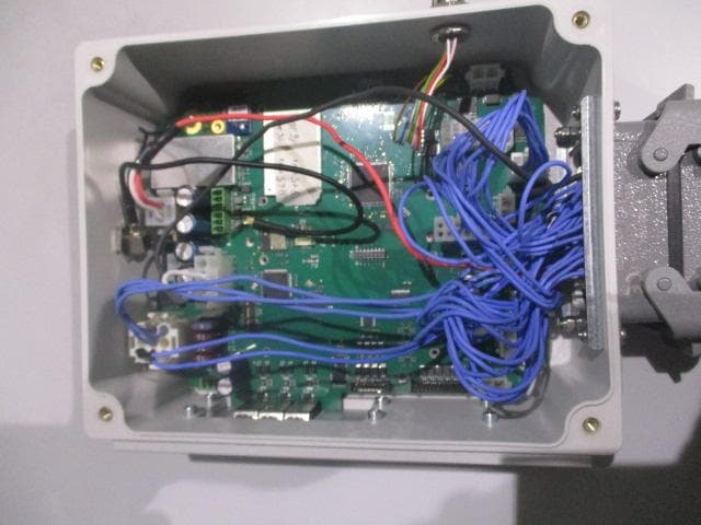
Internal Photos
Independent Testing Laboratory CMC Centro Misure Compatibilità S.r.l. Via dell’Elettronica, 12/C 36016 Thiene (VI) – ITALY Tel./Fax +39 0445 367702 www.cmclab.it - [email protected] Page 1 of 3 INTERNAL PHOTO Independent Testing Laboratory CMC Centro Misure Compatibilità S.r.l. Via dell’Elettronica, 12/C 36016 Thiene (VI) – ITALY Tel./Fax +39 0445 367702 www.cmclab.it - [email protected] Page 2 of 3 Independent Testing Laboratory CMC Centro Misure Compatibilità S.r.l. Via dell’Elettronica, 12/C 36016 Thiene (VI) – ITALY Tel./Fax +39 0445 367702 www.cmclab.it - [email protected] Page 3 of 3
Test Report
CMC Centro Misure Compatibilità S.r.l. Via dell’Elettronica, 12/C 36016 Thiene (VI) – ITALY Tel./Fax +39 0445 367702 www.cmclab.it - [email protected] Independent Testing Laboratory Test report R15007201 Rev. 1.0 Order M150072 page 1 of 69 TEST REPORT nr. R15007201 Federal Communication Commission (FCC) Industry Canada (IC) Test item Description ........................ : TRANSCEIVER UNIT Trademark ......................... : AUTEC Model/Type ...................... : Model PCR Type NKZ21 Test Specification Standard ........................... : FCC Rules & Regulations, Title 47:2013 Part 15 paragraph(s): 203, 204, 207, 209 and 247 RSS-210 Issue 8:December 2010 RSS-GEN Issue 4 – November 2014 Client’s name .............. : AUTEC S.r.l. Address .............................. : Via Pomaroli, 65 – 36030 Caldogno (VI) – ITALY Manufacturer’s name : Same as client Address .............................. : -- Report Tested by ........................... : G. Gandini – Technician Approved by .................... : R. Beghetto – Laboratory Manager Date of issue ..................... : 19.03.15 Contents ............................ : 69 pages This test report shall not be reproduced except in full without the written approval of CMC. The test results presented in this report relate only to the item tested. CMC Centro Misure Compatibilità S.r.l. Via dell’Elettronica, 12/C 36016 Thiene (VI) Test report R15007201 Rev. 1.0 Order M150072 page 2 of 69 Index 1. SUMMARY ..................................................................................................................................................3 2. DESCRIPTION OF EQUIPMENT UNDER TEST (EUT) .....................................................................................4 2.1 TEST SITE .................................................................................................................................................... 4 3. TESTING AND SAMPLING ..........................................................................................................................4 4. OPERATIVE CONDITIONS ..........................................................................................................................4 5. PHOTOGRAPH(S) OF EUT ..........................................................................................................................5 5.1 PHOTOGRAPH(S) OF SETUP ......................................................................................................................... 5 6. EQUIPMENT LIST .........................................................................................................................................7 7. MEASUREMENT UNCERTAINTY ..................................................................................................................8 8. REFERENCE DOCUMENTS..........................................................................................................................9 9. DEVIATION FROM TEST SPECIFICATION .................................................................................................10 10. TEST CASE VERDICTS ...........................................................................................................................10 11. RESULTS ................................................................................................................................................11 11.1 ANTENNA REQUIREMENTS ......................................................................................................................... 12 11.2 CONDUCTED EMISSIONS ........................................................................................................................... 14 11.3 RADIATED EMISSIONS ................................................................................................................................ 18 11.4 20 DB BANDWIDTH ................................................................................................................................... 30 11.5 OCCUPIED BANDWIDTH (99% BW) ........................................................................................................... 35 11.6 CHANNEL SEPARATION ............................................................................................................................. 40 11.7 NUMBER OF HOPPING CHANNELS ............................................................................................................. 43 11.8 TIME OF OCCUPANCY .............................................................................................................................. 46 11.9 BAND EDGE ............................................................................................................................................. 50 11.10 PEAK OUTPUT POWER .............................................................................................................................. 60 11.11 SPURIOUS EMISSION ................................................................................................................................. 65 11.12 MAXIMUM PERMISSIBLE EXPOSURE ............................................................................................................. 69 CMC Centro Misure Compatibilità S.r.l. Via dell’Elettronica, 12/C 36016 Thiene (VI) Test report R15007201 Rev. 1.0 Order M150072 page 3 of 69 1. Summary Standard: FCC Rules & Regulations, Title 47:2013 Part 15 paragraph(s): 203, 204, 207, 209 and 247 RSS-210 Issue 8:December 2010 RSS-GEN Issue 4 – November 2014 Test specifications Environmental Phenomena Tests sequence Result Part 15.203 IC – RSS-GEN Issue 4 Antenna requirements 1 Complies Part 15.207 IC – RSS-GEN Issue 4 Conducted emissions 2 Complies Part 15.209 IC – RSS-GEN Issue 4 Radiated emissions 3 Complies Part 15.247 IC – RSS-GEN Issue 4 20dB Bandwidth 4 Complies IC – RSS-GEN Issue 4 Occupied bandwidth (99% BW) 5 Complies Part 15.247 IC – RSS-GEN Issue 4 Channel Separation 6 Complies Part 15.247 IC …
Text truncated - open the document above for the full version.
Test Report
CMC Centro Misure Compatibilità S.r.l. Via dell’Elettronica, 12/C 36016 Thiene (VI) Test report R15007201 Rev. 1.0 Order M150072 page 36 of 69 Setup Result Frequency (MHz) Graphs 99% bandwidth (kHz) Results 915,05 G15007227 26,194 Complies 921,50 G15007230 26,339 Complies 927,95 G15007220 27,352 Complies CMC Centro Misure Compatibilità S.r.l. Via dell’Elettronica, 12/C 36016 Thiene (VI) Test report R15007201 Rev. 1.0 Order M150072 page 37 of 69 Graphs G15007220 CMC Centro Misure Compatibilità S.r.l. Via dell’Elettronica, 12/C 36016 Thiene (VI) Test report R15007201 Rev. 1.0 Order M150072 page 38 of 69 G15007227 CMC Centro Misure Compatibilità S.r.l. Via dell’Elettronica, 12/C 36016 Thiene (VI) Test report R15007201 Rev. 1.0 Order M150072 page 39 of 69 G15007230 Result: The requirements are met CMC Centro Misure Compatibilità S.r.l. Via dell’Elettronica, 12/C 36016 Thiene (VI) Test report R15007201 Rev. 1.0 Order M150072 page 40 of 69 11.6 Channel separation Test set-up and execution FCC Rules and Regulation; Titles 47 Part 15.247 DA 00-705 RSS 210 Annex 8 Internal procedure PM001 See clause 4 of this test report Test configuration and test method Test site: Laboratory Auxiliary equipment: See clause 4 of this test report EUT exercising See clause 4 of this test report Test equipment used CMC S227 Measurement uncertainty: See clause 7 of this test report Test specification See FCC Part 15.247 Environmental conditions Temperature (ºC) Atmospheric pressure (kPa) Relative humidity (%) 20 100 42 Acceptance limits: Frequency hopping systems shall have hopping channel carrier frequencies separated by a minimum of 25 kHz or the 20 dB bandwidth of the hopping channel, whichever is greater. Alternatively, frequency hopping systems operating in the 2400–2483,5 MHz band may have hopping channel carrier frequencies that are separated by 25 kHz or two-thirds of the 20 dB bandwidth of the hopping channel, whichever is greater, provided the systems operate with an output power no greater than 125 mW CMC Centro Misure Compatibilità S.r.l. Via dell’Elettronica, 12/C 36016 Thiene (VI) Test report R15007201 Rev. 1.0 Order M150072 page 41 of 69 Setup Result Frequency band (MHz) Graphs Channel separation (kHz) Results 902 – 928 G15007234 200 Complies CMC Centro Misure Compatibilità S.r.l. Via dell’Elettronica, 12/C 36016 Thiene (VI) Test report R15007201 Rev. 1.0 Order M150072 page 42 of 69 Graphs G15007234 Result: The requirements are met CMC Centro Misure Compatibilità S.r.l. Via dell’Elettronica, 12/C 36016 Thiene (VI) Test report R15007201 Rev. 1.0 Order M150072 page 43 of 69 11.7 Number of hopping channels Test set-up and execution FCC Rules and Regulation; Titles 47 Part 15.247 DA 00-705 RSS 210 Annex 8 Internal procedure PM001 See clause 4 of this test report Test configuration and test method Test site: Laboratory Auxiliary equipment: See clause 4 of this test report EUT exercising See clause 4 of this test report Test equipment used CMC S227 Measurement uncertainty: See clause 7 of this test report Test specification See FCC Part 15.247 Environmental conditions Temperature (ºC) Atmospheric pressure (kPa) Relative humidity (%) 20 101 42 Acceptance limits: For frequency hopping systems operating in the 902–928 MHz band: if the 20 dB bandwidth of the hopping channel is less than 250 kHz, the system shall use at least 50 hopping frequencies. If the 20 dB bandwidth of the hopping channel is 250 kHz or greater, the system shall use at least 25 hopping frequencies. CMC Centro Misure Compatibilità S.r.l. Via dell’Elettronica, 12/C 36016 Thiene (VI) Test report R15007201 Rev. 1.0 Order M150072 page 44 of 69 Setup Result Graphs Number of hopping channels Results G15007233 64 Complies CMC Centro Misure Compatibilità S.r.l. Via dell’Elettronica, 12/C 36016 Thiene (VI) Test report R15007201 Rev. 1.0 Order M150072 page 45 of 69 Graphs G15007233 Result: The requirements are met CMC Centro Misure Compatibilità S.r.l. Via dell’Elettronica, 12/C 36016 Thiene (VI) Test report R15007201 Rev. 1.0 Order M150072 page 46 of 69 11.8 Time of occupancy Test set-up and execution FCC Rules and Regulation; Titles 47 Part 15.247 DA 00-705 RSS 210 Annex 8 Internal procedure PM001 See clause 4 of this test report Test configuration and test method Test site: Laboratory Auxiliary equipment: See clause 4 of this test report EUT exercising See clause 4 of this test report Test equipment used CMC S227 Measurement uncertainty: See clause 7 of this test report Test specification See FCC Part 15.247 Environmental conditions Temperature (ºC) Atmospheric pressure (kPa) Relative humidity (%) 20 101 42 Acceptance limits: For frequency hopping systems operating in the 902–928 MHz band: if the 20 dB bandwidth of the hopping channel is less than 250 kHz, the system shall use at least 50 hopping frequencies and the average time of occupancy on any frequency shall not be greater than 0.4 seconds within a 20 second period; if the 20 dB bandwidth of the hopping channel is 250 kHz or greater, the system shall use at least 25 hopping frequencies and the average time of occupancy on any frequency shall not be greater than 0.4 seconds within a 10 second period CMC Centro Misure Compatibilità S.r.l. Via dell’Elettronica, 12/C 36016 Thiene (VI) Test report R15007201 Rev. 1.0 Order M150072 page 47 of 69 Setup Result Dwell time of transmission Frequency (MHz) Graphs Dwell time (ms) 921,45 G15007238 14,38 Number of transmissions per period Frequency (MHz) Time between 2 transmission on different channels Number of transmissions (20 s / 0,05 s / 64) 921,45 G15007239 50 ms 6,25…
Text truncated - open the document above for the full version.
Contact Information
Applicant
Antonio Silvestri(Director)
Test Firm
CMC Centro Misure Compatibilit� srlBeghetto Renzo
Technical Specifications
| # | Rule Parts | Frequency Range | Power Output |
|---|---|---|---|
| 1 | 15C | 915.05 MHz - 927.95 MHz | 59.00 mW |
Other Applications from Autec s.r.l.
OQA-TM0N2EN0B3
Jul 20, 2026Transceiver Unit
Equipment Class
DSS - Part 15 Spread Spectrum Transmitter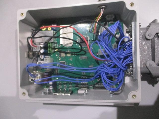
OQA-TX0N2BC0A3
Jul 09, 2026Transceiver unit
Equipment Class
DSS - Part 15 Spread Spectrum Transmitter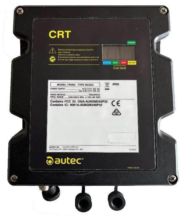
OQA-TR0N2BC0Z3
Jun 09, 2026Transceiver unit
Equipment Class
DSS - Part 15 Spread Spectrum Transmitter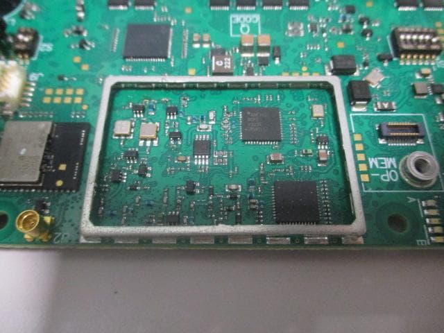
OQA-FSAACT01A
Mar 04, 2026Transceiver Unit
Equipment Class
DSS - Part 15 Spread Spectrum Transmitter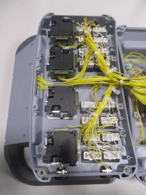
OQA-AX0A02Z0W1
Feb 24, 2026Transceiver Unit
Equipment Class
DSS - Part 15 Spread Spectrum Transmitter