OQA-R402156DRemote Control Receiver
Autec s.r.l.
Click to zoom
Application Details
- Equipment Class
- CYY - Communications Receiver used w/Pt 15 Transmitter
- Date of Grant
- Jun 05, 2006
- Application Purpose
- Original Equipment
- Date of Application
- Jun 05, 2006
- Equipment Note
- Remote Control Receiver
- Frequency Range
- 902.15000000 - 927.72500000
- Company
- Autec s.r.l.
- Country
- Italy
Documents & Files
Document Text
Text extracted from the exhibit documents filed with the FCC. Open a document above to read the original.
Users Manual
AC Receiver System USER’S MANUAL AC Receiver System USER’S MANUAL Follow the indications and warnings given by the machine producer regarding the machine controlled by the radio remote control. The information contained in this manual considers a representative configuration of the radio remote control: please find radio remote control real configuration in the technical data sheet (attached to the manual). If this manual is lost or damaged, ask for a copy from AUTEC. Please specify the serial number of the relative radio remote control. Contact AUTEC if any of the instructions and/or warnings given in this manual are not clear. The information contained in this manual is subject to modification without notice and is not binding. No parts of this manual may be reproduced by any means without the written permission of AUTEC (including recording and photocopying). LI14CAA0-00 - AmEn.fm1 - Index and conventionsPage 1 1 INDEX AND CONVENTIONS 1.1 INDEX 1Index and conventions .......................................................................................... 1 1.1 Index ........................................................................................................................ 1 1.2 Conventions ............................................................................................................. 1 2Introduction ............................................................................................................ 2 2.1 General description.................................................................................................. 2 2.2 Documentation......................................................................................................... 3 2.3 General technical data ............................................................................................. 4 3Receiving unit Type R402 ..................................................................................... 5 3.1 Receiving unit Type R402 technical data................................................................. 6 4Warnings for installation....................................................................................... 7 5Warnings for maintenance.................................................................................... 8 5.1 Routine maintenance ............................................................................................... 8 5.2 Special maintenance (Service Center) .................................................................... 9 5.3 Disposal ................................................................................................................... 9 6Light signals......................................................................................................... 10 6.1 External signals...................................................................................................... 10 6.2 Internal signals....................................................................................................... 10 7Programming........................................................................................................ 11 7.1 Programming the E16SRXUS1 radio receiving module ........................................ 11 7.2 Programming the E16B14AC mother board .......................................................... 12 7.3 Programming the E16RI02B bus board ................................................................. 12 8Receiving unit diagnostics ................................................................................. 13 1.2 CONVENTIONS In this manual, all important information is highlighted in the following symbols and conven- tions: abcd... : WARNINGS abcd... : TECHNICAL DATA abcd... : IMPORTANT TEXTS THIS MANUAL REFERS EXCLUSIVELY TO THE RECEIVING UNIT: THE GENERAL USAGE WARNINGS ARE INCLUDED IN THE TRANSMITTING UNIT MANUAL. BEFORE INSTALLING, STARTING AND USING THE RADIO REMOTE CONTROL, THIS MANUAL MUST BE READ AND UNDERSTOOD BY ALL PEOPLE WHO IN- STALL, USE AND CARRY OUT MAINTENANCE ON THE RADIO REMOTE CONTROL. Page 22 - IntroductionLI14CAA0-00 - AmEn.fm 2 INTRODUCTION 2.1 GENERAL DESCRIPTION Transmit- ting unit Receiving unit Industrial radio remote controls are used to control machines from a distance. Each industrial radio re- mote control is made up of a portable transmitting unit, from which the user can remotely control the machine, and a receiving unit installed on board the machine it - self. The transmitting unit uses radio frequencies to trans- mit a coded message which contains a value called address. Each receiving unit can only decode the messages coming from its own transmitting unit with the same address. This excludes the possibility of an interference activat- ing any system function. If the radio transmission is disturbed, incorrect or interrupted, the receiving unit autonomously stops the whole system. Each radio remote control complies with Part 15 of the FCC rules. Operation is subject to the following conditions: - this device may not cause a harmful interference, and - this device must accept any interference received, including interference that may cause undesired operation. Changes or modifications not expressly approved by the party responsible for compliance could void the user’s authority to operate the equipment. NOTE: This equipment has been tested and found to comply with the limits for a Class B digital device, pursuant to Part 15 of the FCC Rules. These limits are designed to provide reasonable protection against harmful interference in a residential installation. This equipment generates, uses and can radiate radio frequency energy and, if not installed and used in accordance with the instruc- tions, may cause harmful interference to radio communications. However, there is no guarantee that interference will not occur in a particular installation. If this equipment does cause harmful interference to radio or television recep- tion, which can be determined by tur…
Text truncated - open the document above for the full version.
External Photos
Independent Testing Laboratory TÜV Rheinland Appointed Laboratory Accredited by PTT Ministry Competent Body CMC Centro Misure Compatibilità S.r.l. - Via dell’Elettronica, 12/C - 36016 Thiene (VI) - ITALY - tel./fax +39 0445 367702 http://www.cmclab.it e-mail: [email protected] REF. C06042603 Page 1 of 3 EXTERNAL PHOTO Type R402 Model 156D Configuration C02/C12 Independent Testing Laboratory TÜV Rheinland Appointed Laboratory Accredited by PTT Ministry Competent Body CMC Centro Misure Compatibilità S.r.l. - Via dell’Elettronica, 12/C - 36016 Thiene (VI) - ITALY - tel./fax +39 0445 367702 http://www.cmclab.it e-mail: [email protected] REF. C06042603 Page 2 of 3 Independent Testing Laboratory TÜV Rheinland Appointed Laboratory Accredited by PTT Ministry Competent Body CMC Centro Misure Compatibilità S.r.l. - Via dell’Elettronica, 12/C - 36016 Thiene (VI) - ITALY - tel./fax +39 0445 367702 http://www.cmclab.it e-mail: [email protected] REF. C06042603 Page 3 of 3
ID Label/Location Info
Independent Testing Laboratory TÜV Rheinland Appointed Laboratory Accredited by PTT Ministry Competent Body CMC Centro Misure Compatibilità S.r.l. - Via dell’Elettronica, 12/C - 36016 Thiene (VI) - ITALY - tel./fax +39 0445 367702 http://www.cmclab.it e-mail: [email protected] REF. C06042603 Page 1 of 3 EXTERNAL PHOTO Type R402 Model 156D Configuration C02/C12 Independent Testing Laboratory TÜV Rheinland Appointed Laboratory Accredited by PTT Ministry Competent Body CMC Centro Misure Compatibilità S.r.l. - Via dell’Elettronica, 12/C - 36016 Thiene (VI) - ITALY - tel./fax +39 0445 367702 http://www.cmclab.it e-mail: [email protected] REF. C06042603 Page 2 of 3 Independent Testing Laboratory TÜV Rheinland Appointed Laboratory Accredited by PTT Ministry Competent Body CMC Centro Misure Compatibilità S.r.l. - Via dell’Elettronica, 12/C - 36016 Thiene (VI) - ITALY - tel./fax +39 0445 367702 http://www.cmclab.it e-mail: [email protected] REF. C06042603 Page 3 of 3
ID Label/Location Info
RADIO MODULE...............................................E16SRXUS1 FREQUENCY RANGE.......................................902-928MHz PROTECTION DEGREE................................................IP65 TYPE R402MODEL 156D Technical Data RECEIVER POWER SUPPLY 25 450 50-60Hz mA 35 320 50 220 110 100 230 65 V TA969/0 - A0TARG01P0721 FCC ID: OQA-R402156D This radio device complies with Part 15 of the FCC Rules. Operation is subject to the following two conditions: (1) this device may not cause harmful interference, and (2) this device must accept any interference received, including interference that may cause undesired operation.
Internal Photos
Independent Testing Laboratory TÜV Rheinland Appointed Laboratory Accredited by PTT Ministry Competent Body CMC Centro Misure Compatibilità S.r.l. - Via dell’Elettronica, 12/C - 36016 Thiene (VI) - ITALY - tel./fax +39 0445 367702 http://www.cmclab.it e-mail: [email protected] REF. C06042605 Page 1 of 8 INTERNAL PHOTO Type R402 Model 156D Configuration C02 Independent Testing Laboratory TÜV Rheinland Appointed Laboratory Accredited by PTT Ministry Competent Body CMC Centro Misure Compatibilità S.r.l. - Via dell’Elettronica, 12/C - 36016 Thiene (VI) - ITALY - tel./fax +39 0445 367702 http://www.cmclab.it e-mail: [email protected] REF. C06042605 Page 2 of 8 Independent Testing Laboratory TÜV Rheinland Appointed Laboratory Accredited by PTT Ministry Competent Body CMC Centro Misure Compatibilità S.r.l. - Via dell’Elettronica, 12/C - 36016 Thiene (VI) - ITALY - tel./fax +39 0445 367702 http://www.cmclab.it e-mail: [email protected] REF. C06042605 Page 3 of 8 Independent Testing Laboratory TÜV Rheinland Appointed Laboratory Accredited by PTT Ministry Competent Body CMC Centro Misure Compatibilità S.r.l. - Via dell’Elettronica, 12/C - 36016 Thiene (VI) - ITALY - tel./fax +39 0445 367702 http://www.cmclab.it e-mail: [email protected] REF. C06042605 Page 4 of 8 Radio Module Radio Module withou shield Independent Testing Laboratory TÜV Rheinland Appointed Laboratory Accredited by PTT Ministry Competent Body CMC Centro Misure Compatibilità S.r.l. - Via dell’Elettronica, 12/C - 36016 Thiene (VI) - ITALY - tel./fax +39 0445 367702 http://www.cmclab.it e-mail: [email protected] REF. C06042605 Page 5 of 8 Type R402 Model 156D Configuration C12 Independent Testing Laboratory TÜV Rheinland Appointed Laboratory Accredited by PTT Ministry Competent Body CMC Centro Misure Compatibilità S.r.l. - Via dell’Elettronica, 12/C - 36016 Thiene (VI) - ITALY - tel./fax +39 0445 367702 http://www.cmclab.it e-mail: [email protected] REF. C06042605 Page 6 of 8 Independent Testing Laboratory TÜV Rheinland Appointed Laboratory Accredited by PTT Ministry Competent Body CMC Centro Misure Compatibilità S.r.l. - Via dell’Elettronica, 12/C - 36016 Thiene (VI) - ITALY - tel./fax +39 0445 367702 http://www.cmclab.it e-mail: [email protected] REF. C06042605 Page 7 of 8 Independent Testing Laboratory TÜV Rheinland Appointed Laboratory Accredited by PTT Ministry Competent Body CMC Centro Misure Compatibilità S.r.l. - Via dell’Elettronica, 12/C - 36016 Thiene (VI) - ITALY - tel./fax +39 0445 367702 http://www.cmclab.it e-mail: [email protected] REF. C06042605 Page 8 of 8 Radio Module Radio Module withou shield
Operational Description
1 Operational Description for Type R402 Model 156D receiving unit Operational Description for Type R402 Model 156D receiving unit 1Identification of the unit where: TYPE: identifies type of unit (transmitting, receiving or transceiving), type of casing and used electronic modules. MODEL: differentiates power supply, type of actuators and radio frequency band CONFIGURATION: refers to the specific set of components and accessories of the unit 2Difference between the units There are some Configurations which differ each other for the used extension interface (card) and for the used antenna: Configuration C01: - embedded antenna Configuration C02: - antenna with stylus and with a cable 1 - 5 metres Configuration C03: - E16RI02A bus board - embedded antenna - no extension interface (card) Configuration C04: - E16RI02A bus board - antenna with stylus and with a cable 1 - 5 metres - no extension interface (card) Configuration C05: - E16RI02A bus board - embedded antenna - converter d/a extension interface (card) E16RIV15 Configuration C06: - E16RI02A bus board - antenna with stylus and with a cable 1 - 5 metres - converter d/a extension interface (card) E16RIV15 Configuration C07: - E16RI02A bus board - embedded antenna Ty p eR402 Model156D ConfigurationsC02 and C12 Equipmentremote control receiving unit Receiving radio moduleE16SRXUS1 Used frequency band902 - 928 MHz FCC IdentifierOQA-R402156D Manufacturer AUTEC srl Via Pomaroli, 65 I-36030 CALDOGNO (VI) 2 Operational Description for Type R402 Model 156D receiving unit - converter d/a extension interface (card) E16RIV4A Configuration C08: - E16RI02A bus board - antenna with stylus and with a cable 1 - 5 metres - converter d/a extension interface (card) E16RIV4A Configuration C09: - E16RI02A bus board - embedded antenna - converter d/a extension interface (card) E16RIV1A Configuration C10: - E16RI02A bus board - antenna with stylus and with a cable 1 - 5 metres - converter d/a extension interface (card) E16RIV1A Configuration C11: - E16RI02A bus board - embedded antenna - converter d/a extension interface (card) E16RIR4A Configuration C12: - E16RI02A bus board - antenna with stylus and with a cable 1 - 5 metres - converter d/a extension interface (card) E16RIR4A Configuration C13: - E16RI02A bus board - embedded antenna - converter d/a extension interface (card) E16RI01A Configuration C14: - E16RI02A bus board - antenna with stylus and with a cable 1 - 5 metres - converter d/a extension interface (card) E16RI01A (card) E16RIR8A 3 Operational Description for Type R402 Model 156D receiving unit 3Operational description Industrial radio remote controls are used to command machines from a distance. Each industrial radio remote control is made up of a portable transmitting unit, from which the user can remotely control the machine, and a receiving unit installed on board the machine itself. The receiving unit contains E16SRXUS1. It is the radio receiving module. A double conversion supeheterodyne radio circuit demodulates the tuned carrier (32 different frequencies in the 902-928 MHz band, channel spacing 25 kHz) and so recovers the data tel- egram to be decoded by a following logic section. Decoding is performed with two-channel redundancy, so as to achieve protection against single faults; if both channels recognize a tel- egram containing the same address stored in the "address key" EEPROM, then commands encoded on the telegram are output to be used for relay driving. Relays are housed on E16B14AC master board, together with a suitable power supply section (for details see relative block diagrams). Telegrams coming from a transmitter with address different from that stored in the "address key", as well as any other radio noise, will be discarded; the receiver will automatically bring the system to safe state (no command output) if no valid signal is received for more than 0.35 or 1 sec (user selectable). 4 Operational Description for Type R402 Model 156D receiving unit 4Exploded view Casing E16RI02A bus board E16B14AC master board (contains the relais and their outputs for the wiring) Antenna with stylus and with cable 1 - 5 metres Embedded antenna Extention interface (card) E16SRXUS1 receiving module (contains the decoder and radio receiver) 5 Operational Description for Type R402 Model 156D receiving unit 5Technical data E16SRXUS1 receiving radio module * if the antenna is dedicated, it is λ/4 monopole antenna with cable 1-5 metres (see exploded view). Used frequency band902 - 928 MHz Type of modulation2200 - 2600 Baud GFSK Channel spacing25 kHz Sensitivity-116 dBm (SINAD > 12 dB) Type superheterodine (double conversion) Duty cycle up to 100 % (continuous duty), depends on user’s need Duplex directionsimplex Antenna typeembedded * Data telegram132 bit Hamming distance> 8 Probability of non-recognition of error<10 exp-11 6 Operational Description for Type R402 Model 156D receiving unit
Test Report
Independent Testing Laboratory TÜV Rheinland Appointed Laboratory Accredited by PTT Ministry Competent Body CMC Centro Misure Compatibilità S.r.l. - Via dell’Elettronica, 12/C - 36016 Thiene (VI) - ITALY - tel./fax +39 0445 367702 http://www.cmclab.it e-mail: [email protected] Test report R06042601_rev20 Rev. 2.0 Order M060426 page 1 of 32 TEST REPORT nr. R06042601_rev20 This test report cancel and replace document nr. R06042601 date 18.05.06 Test item Description.................................... : RECEIVER UNIT Trademark ..................................... : AUTEC Model and/or type reference......... : Type R402 Model 156D Configuration C01/C02/C11/C12 Manufacturer................................. : Same as client Serial Number ............................... : -- Client Name ............................................. : AUTEC S.r.l. Address ......................................... : Via Pomaroli, 65 ....................................................... : 36030 Caldogno (VI) – ITALY Test specification Standard ........................................ : FCC Rules & Regulations, Title 47 (2005) - Part 15 paragraph(s) : 109, 107 and 111 Report Tested by (+ signature) ............... : G.. Chiumento - Supervisor Approved by (+ signature) ......... : R. Beghetto - Laboratory Manager Date of issue.................................. : 31.05.06 Contents ........................................ : 32 pages This test report shall not be reproduced except in full without the written approval of CMC. The test results presented in this report relate only to the item tested. CMC Centro Misure Compatibilità S.r.l. Via dell’Elettronica, 12/C 36016 Thiene (VI) Test report R06042601_rev20 Rev. 2.0 Order M060426 page 2 of 32 Index 1. SUMMARY ........................................................................................................................................................... 3 2. DESCRIPTION OF EQUIPMENT UNDER TEST (EUT)............................................................................... 4 3. TESTING AND SAMPLING............................................................................................................................... 5 4. OPERATIVE CONDITIONS .............................................................................................................................. 5 5. PHOTOGRAPH(S) OF EUT ............................................................................................................................... 6 6. EQUIPMENT LIST ............................................................................................................................................ 14 7. MEASUREMENT UNCERTAINTY ................................................................................................................ 16 8. REFERENCE DOCUMENTS ........................................................................................................................... 16 9. DEVIATION FROM TEST SPECIFICATION...............................................................................................17 10. TEST CASE VERDICTS .............................................................................................................................. 17 11. RESULTS........................................................................................................................................................ 17 11.1 EMISSION OF MAINS TERMINAL DISTURBANCE VOLTAGE (CONTINUOUS DISTURBANCE) ............................... 18 11.2 RADIATED EMISSION 30-1000 MHZ............................................................................................................. 19 11.3 ANTENNA POWER CONDUCTION LIMITS FOR RECEIVERS............................................................................... 20 12. GRAPHS AND TABLES ............................................................................................................................... 21 CMC Centro Misure Compatibilità S.r.l. Via dell’Elettronica, 12/C 36016 Thiene (VI) Test report R06042601_rev20 Rev. 2.0 Order M060426 page 3 of 32 1. Summary Emission: FCC Rules & Regulations, Title 47 Test specifications Environmental Phenomena Tests sequence Result Part 15.109 Radiated Emission 1 Complies Part 15.107 RF Disturbance voltage: - continuous 2 Complies Part 15.111 Antenna power conduction limits for receivers 3 Complies The Test Report was given to the Client representatives for necessary documentation of ratification of the tested equipment and it is valid for the FCC certification. CMC Centro Misure Compatibilità S.r.l. Via dell’Elettronica, 12/C 36016 Thiene (VI) Test report R06042601_rev20 Rev. 2.0 Order M060426 page 4 of 32 2. Description of Equipment under test (EUT) Power supply ......................................................................... : 120Vac 50Hz single-phase + earth Type of equipment............................................................... : Transmitter Unit ; Receiver Unit ; Fixed station Portable station Mobile station Receiver class ........................................................................ : -- Alignment range .................................................................... : 902 – 928 MHz Switching frequency .............................................................. : 902 – 928 MHz Number of channels.............................................................. : -- Channel separation ............................................................... : -- Modulation............................................................................ : -- Extreme conditions ................................................................ : -- Maximum transmitter output power .................................... : -- Information on antenna ........................................................ :; Integrated Extern Other: Duty cycle ............................................................................. : -- Mode of operation......…
Text truncated - open the document above for the full version.
Contact Information
Applicant
Antonio Silvestri(Director)
Test Firm
CMC Centro Misure Compatibilit� srlBeghetto Renzo
Technical Specifications
| # | Rule Parts | Frequency Range | Power Output |
|---|---|---|---|
| 1 | 15B | 902.15 MHz - 927.725 MHz | - |
Other Applications from Autec s.r.l.
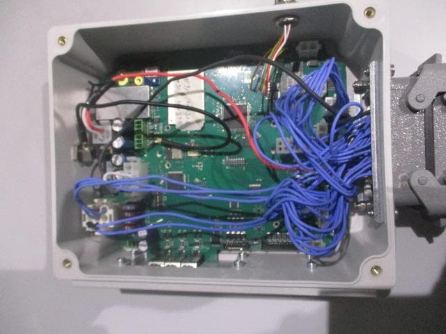
OQA-TM0N2EN0B3
Jul 20, 2026Transceiver Unit
Equipment Class
DSS - Part 15 Spread Spectrum Transmitter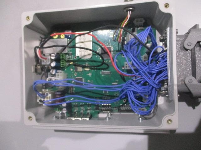
OQA-TX0N2BC0A3
Jul 09, 2026Transceiver unit
Equipment Class
DSS - Part 15 Spread Spectrum Transmitter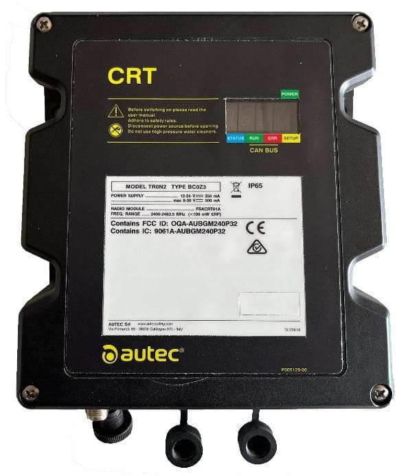
OQA-TR0N2BC0Z3
Jun 09, 2026Transceiver unit
Equipment Class
DSS - Part 15 Spread Spectrum Transmitter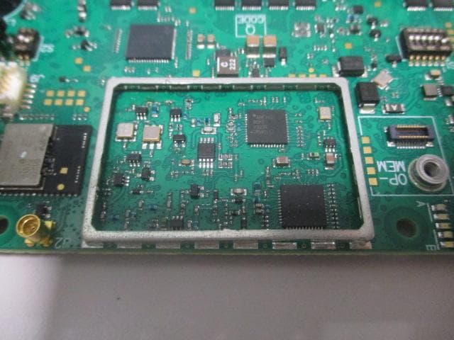
OQA-FSAACT01A
Mar 04, 2026Transceiver Unit
Equipment Class
DSS - Part 15 Spread Spectrum Transmitter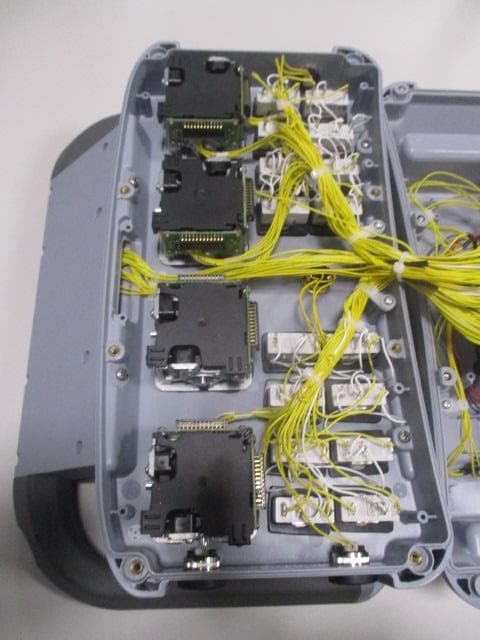
OQA-AX0A02Z0W1
Feb 24, 2026Transceiver Unit
Equipment Class
DSS - Part 15 Spread Spectrum Transmitter