OQA-R402157DReceiver for Radio Remote Control
Autec s.r.l.
Click to zoom
Application Details
- Equipment Class
- CYY - Communications Receiver used w/Pt 15 Transmitter
- Date of Grant
- May 09, 2007
- Application Purpose
- Original Equipment
- Date of Application
- May 09, 2007
- Equipment Note
- Receiver for Radio Remote Control
- Frequency Range
- 902.00000000 - 928.00000000
- Company
- Autec s.r.l.
- Country
- Italy
Documents & Files
Document Text
Text extracted from the exhibit documents filed with the FCC. Open a document above to read the original.
Users Manual
Modular Series Master/Slave system Master/Master system User Manual Modular Series Master/Slave system Master/Master system User Manual Follow the indications and warnings given by the machine producer regarding the machine on which the radio remote control is installed. If this manual is lost or damaged, ask for a copy from Autec. Please specify the serial number of the related radio remote control. Contact AUTEC if any of the instructions and/or warnings given in this manual is not clear. The information contained in this manual is subject to modification without notice and is not binding. No part of this manual may be reproduced, in any form or by any means, without written permission of Autec (including recording and photocopying). - 1 - LIMM&SA0-00.fm INDEX 1Introduction ...................................................................................... 2 1.1Conventions......................................................................................... 2 1.2System description ............................................................................... 2 1.3Conformity .......................................................................................... 4 1.4Risk analysis........................................................................................ 5 1.5Documentation..................................................................................... 5 1.6Modular Series technical data................................................................. 6 1.7Frequencies ......................................................................................... 6 2Transmitting units ............................................................................. 7 2.1Description of MK12 and MK10 ............................................................... 7 2.2Description of MJ .................................................................................. 8 2.3Warnings for the use of the transmitting units .......................................... 9 2.4Warnings for the maintenance of the transmitting units ............................. 9 3Receiving unit .................................................................................. 10 3.1Description of the receiving unit ........................................................... 10 3.2Inner parts of the “Master/Slave” receiving units .................................... 11 3.3Inner parts of the “Master/Master” receiving units................................... 12 3.4General warnings for the installation of the receiving unit ........................ 12 3.5Specific warnings for the installation of the receiving unit......................... 14 3.6Warnings for the maintenance of the receiving unit ................................. 14 3.7External signal lights of the receiving unit .............................................. 15 3.8Internal signal lights of the receiving unit .............................................. 16 4Operating mode of “Master/Slave” .................................................. 17 4.1Command “Take/Release 2” or “Release 2” ............................................ 17 4.2Power on and start up ......................................................................... 18 5Operating mode of “Master/Master”................................................ 19 5.1Command “Take/Release” ................................................................... 19 5.2Power on and start up ......................................................................... 20 6Operating mode of the transmitting units ........................................ 21 6.1Command activation ........................................................................... 21 6.2STOP ................................................................................................ 22 6.3Battery ............................................................................................. 22 6.4Signals.............................................................................................. 22 6.5Switching off...................................................................................... 22 7Maintenance .................................................................................... 23 7.1Routine maintenance .......................................................................... 23 7.2Special maintenance ........................................................................... 24 7.3Disposal ............................................................................................ 24 8Programming ................................................................................... 25 8.1Programming the transmitting module................................................... 25 8.2Programming the receiving module ....................................................... 26 8.3Programming the master board E16B14AC............................................. 27 8.4Programming the bus board E16RI02_ .................................................. 27 8.5Frequency tables ................................................................................ 27 9Diagnostics ...................................................................................... 28 9.1Transmitting unit diagnostics ............................................................... 28 9.2Receiving unit diagnostics.................................................................... 29 1 Introduction - 2 - LIMM&SA0-00.fm 1INTRODUCTION 1.1Conventions In this manual, all important information is highlighted in the following symbols and conven- tions: 1.2System description Industrial radio remote controls of the Modular series are used to control machines from a dis- tance. Each industrial radio remote control is made up of at least one portable transmitting unit, from which the user can remotely control the machine, and at least one receiving unit installed on board the machine itself. Each transmitting unit uses radio frequencies to transmit a cod…
Text truncated - open the document above for the full version.
External Photos
Independent Testing Laboratory TÜV Rheinland Appointed Laboratory Accredited by PTT Ministry Competent Body CMC Centro Misure Compatibilità S.r.l. - Via dell’Elettronica, 12/C - 36016 Thiene (VI) - ITALY - tel./fax +39 0445 367702 http://www.cmclab.it e-mail: [email protected] REF. C06164502 Page 1 of 2 EXTERNAL PHOTO Type R402 Model 157D Configuration C35 Independent Testing Laboratory TÜV Rheinland Appointed Laboratory Accredited by PTT Ministry Competent Body CMC Centro Misure Compatibilità S.r.l. - Via dell’Elettronica, 12/C - 36016 Thiene (VI) - ITALY - tel./fax +39 0445 367702 http://www.cmclab.it e-mail: [email protected] REF. C06164502 Page 2 of 2 EXTERNAL PHOTO Type R402 Model 157D Configuration C36
ID Label/Location Info
RADIO MODULE...............................................E16SRXUS1 FREQUENCY RANGE.......................................902-928MHz PROTECTION DEGREE................................................IP65 TYPE R402MODEL 157D Technical Data RECEIVER POWER SUPPLY 25 450 50-60Hz mA 35 320 50 220 110 100 230 65 V FCC ID: OQA-R402157D This radio device complies with Part 15 of the FCC Rules. Operation is subject to the following two conditions: (1) this device may not cause harmful interference, and (2) this device must accept any interference received, including interference that may cause undesired operation. A0TARG01P0742/TA995-00
Internal Photos
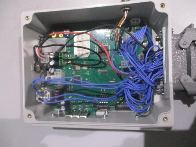
Independent Testing Laboratory TÜV Rheinland Appointed Laboratory Accredited by PTT Ministry Competent Body CMC Centro Misure Compatibilità S.r.l. - Via dell’Elettronica, 12/C - 36016 Thiene (VI) - ITALY - tel./fax +39 0445 367702 http://www.cmclab.it e-mail: [email protected] REF. C06164504 Page 1 of 12 INTERNAL PHOTO Type R402 Model 157D Configuration C35 Independent Testing Laboratory TÜV Rheinland Appointed Laboratory Accredited by PTT Ministry Competent Body CMC Centro Misure Compatibilità S.r.l. - Via dell’Elettronica, 12/C - 36016 Thiene (VI) - ITALY - tel./fax +39 0445 367702 http://www.cmclab.it e-mail: [email protected] REF. C06164504 Page 2 of 12 Independent Testing Laboratory TÜV Rheinland Appointed Laboratory Accredited by PTT Ministry Competent Body CMC Centro Misure Compatibilità S.r.l. - Via dell’Elettronica, 12/C - 36016 Thiene (VI) - ITALY - tel./fax +39 0445 367702 http://www.cmclab.it e-mail: [email protected] REF. C06164504 Page 3 of 12 1 st radio module Independent Testing Laboratory TÜV Rheinland Appointed Laboratory Accredited by PTT Ministry Competent Body CMC Centro Misure Compatibilità S.r.l. - Via dell’Elettronica, 12/C - 36016 Thiene (VI) - ITALY - tel./fax +39 0445 367702 http://www.cmclab.it e-mail: [email protected] REF. C06164504 Page 4 of 12 2 nd radio module Independent Testing Laboratory TÜV Rheinland Appointed Laboratory Accredited by PTT Ministry Competent Body CMC Centro Misure Compatibilità S.r.l. - Via dell’Elettronica, 12/C - 36016 Thiene (VI) - ITALY - tel./fax +39 0445 367702 http://www.cmclab.it e-mail: [email protected] REF. C06164504 Page 5 of 12 Independent Testing Laboratory TÜV Rheinland Appointed Laboratory Accredited by PTT Ministry Competent Body CMC Centro Misure Compatibilità S.r.l. - Via dell’Elettronica, 12/C - 36016 Thiene (VI) - ITALY - tel./fax +39 0445 367702 http://www.cmclab.it e-mail: [email protected] REF. C06164504 Page 6 of 12 Independent Testing Laboratory TÜV Rheinland Appointed Laboratory Accredited by PTT Ministry Competent Body CMC Centro Misure Compatibilità S.r.l. - Via dell’Elettronica, 12/C - 36016 Thiene (VI) - ITALY - tel./fax +39 0445 367702 http://www.cmclab.it e-mail: [email protected] REF. C06164504 Page 7 of 12 INTERNAL PHOTO Type R402 Model 157D Configuration C36 Independent Testing Laboratory TÜV Rheinland Appointed Laboratory Accredited by PTT Ministry Competent Body CMC Centro Misure Compatibilità S.r.l. - Via dell’Elettronica, 12/C - 36016 Thiene (VI) - ITALY - tel./fax +39 0445 367702 http://www.cmclab.it e-mail: [email protected] REF. C06164504 Page 8 of 12 Independent Testing Laboratory TÜV Rheinland Appointed Laboratory Accredited by PTT Ministry Competent Body CMC Centro Misure Compatibilità S.r.l. - Via dell’Elettronica, 12/C - 36016 Thiene (VI) - ITALY - tel./fax +39 0445 367702 http://www.cmclab.it e-mail: [email protected] REF. C06164504 Page 9 of 12 1 st radio module Independent Testing Laboratory TÜV Rheinland Appointed Laboratory Accredited by PTT Ministry Competent Body CMC Centro Misure Compatibilità S.r.l. - Via dell’Elettronica, 12/C - 36016 Thiene (VI) - ITALY - tel./fax +39 0445 367702 http://www.cmclab.it e-mail: [email protected] REF. C06164504 Page 10 of 12 2 nd radio module Independent Testing Laboratory TÜV Rheinland Appointed Laboratory Accredited by PTT Ministry Competent Body CMC Centro Misure Compatibilità S.r.l. - Via dell’Elettronica, 12/C - 36016 Thiene (VI) - ITALY - tel./fax +39 0445 367702 http://www.cmclab.it e-mail: [email protected] REF. C06164504 Page 11 of 12 Independent Testing Laboratory TÜV Rheinland Appointed Laboratory Accredited by PTT Ministry Competent Body CMC Centro Misure Compatibilità S.r.l. - Via dell’Elettronica, 12/C - 36016 Thiene (VI) - ITALY - tel./fax +39 0445 367702 http://www.cmclab.it e-mail: [email protected] REF. C06164504 Page 12 of 12
Operational Description
1 Operational Description for Type R402 Model 157D receiving unit Operational Description for Type R402 Model 157D receiving unit 1Identification of the unit where: TYPE: identifies type of unit (transmitting, receiving or transceiving), type of casing and used electronic modules. MODEL: differentiates power supply, type of actuators and radio frequency band CONFIGURATION: refers to the specific set of components and accessories of the unit 2Difference between the units There are some Configurations which differ each other for the used extension interface (card) and for the used antenna: Configuration C27: -E16RI02D bus board - embedded antenna - extension interface (card) Configuration C28: -E16RI02D bus board - antenna with stylus and with a cable 1 - 5 metres - no extension interface (card) Configuration C29: -E16RI02D bus board - embedded antenna - extension interface (card) E16RIV15 - one extension interface (card) chosen amongst E16RIV15, E16RIV4A, E16RIV1A, E16RIR4A, E16RI01A Configuration C30: -E16RI02D bus board - antenna with stylus and with a cable 1 - 5 metres - extension interface (card) E16RIV15 - one extension interface (card) chosen amongst E16RIV15, E16RIV4A, E16RIV1A, E16RIR4A, E16RI01A Ty p eR402 Model157D ConfigurationsC35 Equipmentremote control receiving unit Receiving radio modulestwo E16SRXUS1 modules Used frequency band902 - 928 MHz FCC IdentifierOQA-R402157D Manufacturer AUTEC srl Via Pomaroli, 65 I-36030 CALDOGNO (VI) 2 Operational Description for Type R402 Model 157D receiving unit Configuration C31: - E16RI02D bus board - embedded antenna - extension interface (card) E16RIV4A - one extension interface (card) chosen amongst E16RIV15, E16RIV4A, E16RIV1A, E16RIR4A, E16RI01A Configuration C32: - E16RI02D bus board - antenna with stylus and with a cable 1 - 5 metres - extension interface (card) E16RIV4A - one extension interface (card) chosen amongst E16RIV15, E16RIV4A, E16RIV1A, E16RIR4A, E16RI01A Configuration C33: - E16RI02D bus board - embedded antenna - extension interface (card) E16RIV1A - one extension interface (card) chosen amongst E16RIV15, E16RIV4A, E16RIV1A, E16RIR4A, E16RI01A Configuration C34: - E16RI02D bus board - antenna with stylus and with a cable 1 - 5 metres - extension interface (card) E16RIV1A - one extension interface (card) chosen amongst E16RIV15, E16RIV4A, E16RIV1A, E16RIR4A, E16RI01A Configuration C35: - E16RI02D bus board - antenna with stylus and with a cable 1 - 5 metres - extension interface (card) E16RIR4A - one extension interface (card) chosen amongst E16RIV15, E16RIV4A, E16RIV1A, E16RIR4A, E16RI01A Configuration C36: - E16RI02D bus board - antenna with stylus and with a cable 1 - 5 metres - extension interface (card) E16RIR4A - one extension interface (card) chosen amongst E16RIV15, E16RIV4A, E16RIV1A, E16RIR4A, E16RI01A Configuration C37: - E16RI02D bus board - embedded antenna - extension interface (card) E16RI01A - one extension interface (card) chosen amongst E16RIV15, E16RIV4A, E16RIV1A, E16RIR4A, E16RI01A Configuration C38: - E16RI02D bus board - antenna with stylus and with a cable 1 - 5 metres - extension interface (card) E16RI01A - one extension interface (card) chosen amongst E16RIV15, E16RIV4A, E16RIV1A, E16RIR4A, E16RI01A 3 Operational Description for Type R402 Model 157D receiving unit 3Operational description Industrial radio remote controls are used to command machines from a distance. Each industrial radio remote control is made up of a portable transmitting unit, from which the user can remotely control the machine, and a receiving unit installed on board the machine itself. The receiving unit contains E16SRXUS1. It is the radio receiving module. A double conversion supeheterodyne radio circuit demodulates the tuned carrier (32 different frequencies in the 902-928 MHz band, channel spacing 25 kHz) and so recovers the data tel- egram to be decoded by a following logic section. Decoding is performed with two-channel redundancy, so as to achieve protection against single faults; if both channels recognize a tel- egram containing the same address stored in the "address key" EEPROM, then commands encoded on the telegram are output to be used for relay driving. Relays are housed on E16B14AC master board, together with a suitable power supply section (for details see relative block diagrams). Telegrams coming from a transmitter with address different from that stored in the "address key", as well as any other radio noise, will be discarded; the receiver will automatically bring the system to safe state (no command output) if no valid signal is received for more than 0.35 or 1 sec (user selectable). 4 Operational Description for Type R402 Model 157D receiving unit 4Exploded view Casing E16RI02D bus board E16B14AC master board (contains the relais and their outputs for the wiring) Antenna with stylus and with cable 1 - 5 metres Embedded antenna Extention interface (card) E16SRXUS1 receiving module (contains the decoder and radio receiver) 5 Operational Description for Type R402 Model 157D receiving unit 5Technical data E16SRXUS1 receiving radio module * as an option, dedicated λ/4 monopole antenna with cable 1-5 metres may also be used (see exploded view). Used frequency band902 - 928 MHz Type of modulation2200 - 2600 Baud GFSK Channel spacing25 kHz Sensitivity-116 dBm (SINAD > 12 dB) Type superheterodine (double conversion) Duty cycle up to 100 % (continuous duty), depends on user’s need Duplex directionsimplex Antenna typeembedded * Data telegram132 bit Hamming distance> 8 Probability of non-recognition of error<10 exp-11 6 Operational Description for Type R402 Model 157D receiving unit
Schematics
AA BB CC DD EE 4 4 3 3 2 2 1 1 E1 E14 E6 E5 E4 E13 E20 E16 E21 E9 DATA_IN E17 E8 E7 E19 E15 E12 E18 E11 E22 E3 E2 E10 E7E1E2E3E4E5E9E8E10E11E12E13E14E15E16E17E18E22E21E20E19E6 STOP1 DIP_3DIP_0M_ADIP_4 /STOP2 SENSE_STOP_1 STOP1 TEMP SENSE_SAFETY_A SAFETY_CHECK_B MEM_CS MEM_SK MEM_DI MEM_CS MEM_DI MEM_SK OP_2_B M_ADIP_4DIP_3DIP_0 RF_ENA RF_ENA OP_2_AOP_1_A P7_AUTJUMP1JUMP2 JUMP1 ABI_KEY ABI_KEY MEM_DO MEM_DO EME_1EME_1 EME_1 P7_AUT JUMP2 RES_A RES_A OP_1_A OP_2_A RES_B RES_B BAUD_CLOCK SAFETY_CHECK_A SENSE_SAFETY_ASENSE_SAFETY_BSAFETY_OUT_B SAFETY_OUT_A SAFETY_OUT_B SENSE_STOP_2 TEMP SAFETY_OUT_A ENABLE ENABLE ENABLE ENABLE /STOP2 DIP_1DIP_2 LTC_OUT LTC_OUTDIP_2DIP_1 SENSE_STOP_1 OP_1_B SENSE_STOP_2 OP_2_BOP_1_B RETIMED_DATA SENSE_SAFETY_BSENSE_SAFETY_BSENSE_SAFETY_BSENSE_SAFETY_BSENSE_SAFETY_BSENSE_SAFETY_BSENSE_SAFETY_BSENSE_SAFETY_BSENSE_SAFETY_BSENSE_SAFETY_BSENSE_SAFETY_BSENSE_SAFETY_BSENSE_SAFETY_BSENSE_SAFETY_BSENSE_SAFETY_BSENSE_SAFETY_BSENSE_SAFETY_BSENSE_SAFETY_B ANTRX_SIG L_D PLL_CK OPZ2 TS SAFETY ANT_BIAS RES_RL SQUELCH DIV_ENA OPZ1 RES_A RES_B RES_ARES_B PLL_DIPLL_LE OPZ1OPZ2 SAFETY TS VCCA VCCA VCCB VCC VCC VCCA VCCA VCCA VCC VCCB VCCB VCCB VCCB +12V VCCB VCCB VCC VCCA VCCA VCCA VCCA VCCB VCCB VCC +12V +VS +24V VCCA VCCB VCCA VCC VCC VCCB VCC VCCB VCCA VCCB VCC VCC VCC VCC VCC +VS +24V+24V VCC +VS VCC VCC VCC VCC VCC Rev. Data Revision History 26/06/0414/09/0516/06/0610/10/06<><><><> First editionSheet 2 revisedAlternative X2 quartz added; U8,C25 updated; sheet 2 revised; TA1 removed; ESD shield addedC108 added, D26 value of components updated, PCB revised<><><><> 00010203<><><><> Rev. Data Revision History 26/06/0414/09/0516/06/0610/10/06<><><><> First editionSheet 2 revisedAlternative X2 quartz added; U8,C25 updated; sheet 2 revised; TA1 removed; ESD shield addedC108 added, D26 value of components updated, PCB revised<><><><> 00010203<><><><> Rev. Data Revision History 26/06/0414/09/0516/06/0610/10/06<><><><> First editionSheet 2 revisedAlternative X2 quartz added; U8,C25 updated; sheet 2 revised; TA1 removed; ESD shield addedC108 added, D26 value of components updated, PCB revised<><><><> 00010203<><><><> di Via Pomaroli, 6536030 Caldogno (VI)Tel. 0444-901000 Fax. 0444-901060 Cod:Richiesto:Descrizione:Disegnato:Approvato:Verificato: Rif cs:File:Data:Foglio: Size: RADIO REMOTE CONTROL Rev: Confidential Material - Documento Riservato SC000260.dsn12 A2 F0RXDE06E08A0 (E16SRXUS1 Z.3 915Mhz) E16S- receiver module: logic and power circuitsBonan A.Giaretton D.Terreran M.Bonan A. RD010.1 03 di Via Pomaroli, 6536030 Caldogno (VI)Tel. 0444-901000 Fax. 0444-901060 Cod:Richiesto:Descrizione:Disegnato:Approvato:Verificato: Rif cs:File:Data:Foglio: Size: RADIO REMOTE CONTROL Rev: Confidential Material - Documento Riservato SC000260.dsn12 A2 F0RXDE06E08A0 (E16SRXUS1 Z.3 915Mhz) E16S- receiver module: logic and power circuitsBonan A.Giaretton D.Terreran M.Bonan A. RD010.1 03 di Via Pomaroli, 6536030 Caldogno (VI)Tel. 0444-901000 Fax. 0444-901060 Cod:Richiesto:Descrizione:Disegnato:Approvato:Verificato: Rif cs:File:Data:Foglio: Size: RADIO REMOTE CONTROL Rev: Confidential Material - Documento Riservato SC000260.dsn12 A2 F0RXDE06E08A0 (E16SRXUS1 Z.3 915Mhz) E16S- receiver module: logic and power circuitsBonan A.Giaretton D.Terreran M.Bonan A. RD010.1 03 STARTE1 (F2)E2 (S2)E3 (F3)E4 (S3)E5 (F4)E6 (S4)E7 (F5)E8 (S5)E9 (F6)E10 (S6)E11 (F8)E12 (S8)E14 (S9)E15 (F10)E16 (S10)E17 (F11)E20 (S13)E21 (F12)E22 (S12)E19 (F13)E18 (S11)E13 (F9) IN_STOP_ASTOP_AIN_STOP_B STOP_B FILO1FILO2 PROG 8X2CH PROG 12X2CH DEMAG Main VCC regulator with over-voltage protections 12V power supply and FPGA activity Watch-dog Two lines with independent protection are provided:-VCCA for Lpa25R-VCCB for Lpa26R Monitors the activity of Lpa25R clock generator (used also by Lpa26R).Pulls-up both RES_A and RES_B lines when "+12V" power supply is higher than 8V.Also adds a redundant monitoring on VCCA,which must be >=3.5V. Vcc_monitor_2Activates (forces LOW) both RES_A and RES_B reset lines when "VCCA" power supply falls below 3V A bias voltage may superposed to the antenna wire to control some ext. circuits, according to DSW2 setting2 Input: antenna5 Output: DATA_out6 Input: DATA_in7 Input: pre-regulated power supply for electronics8 Output: follows "+24V" if VCC_monitor_1 and SAFETY_CHECK are OK9, 10 Self-configuration pins (two, not safety related)11 Output conn. to "+VS" when both STOP1 and STOP2 closed16..37 Output lines of relay drivers for commands E1..E2212 Output line of START relay driver 15 Output line of SAFETY relay driver41,42 Self-configuration pins (two not safety related)37 Output: time delayed STOP (not for safety function)38 Input power for STOP_A relay driver39 Output of STOP_A relay driver40 Input power for STOP_B relay driver41 Output of STOP_B relay driver45,46 Input: relay coils power supply (12 or 24V) integrated 5V to 12/24Vrelay drivers for commands 5V to 12/24V driverfor STOP_A relay(driven by STOP1)5V to 12/24V driverfor STOP_B relay(driven by /STOP2 with logic inversion) Custom output config.(not safety critical) DATA_out coming from radio receiver 5V to 12/24V relay driverfor SAFETY with dual inputsand feedback signals Vcc_monitor_2Activates RES_A, RES_B (force LOW) and cuts +Vs line when"VCCB" power supplyfalls below 3V Switch for cutting +Vs line:opens all relays if VCCB isout of specs. OR SAFETY_CHECKs are not OK Switch for cutting ENABLE line:opens command and SAFETY relaysif STOP relays are not closed feedback signals from STOP relaysused to drive the ENABLE line 5V to 12/24V relay driverfor time-delayed auxiliary STOP output (not for safety function) Connector for the "address_key_EEPROM"N.B.:-LTC_OUT and RF_ENA used only during production testing;-"auxiliary EEPROM" listed in the concept block diagramE16BLOCKS rev.1has not been implemented Both FPGAs have reset independent lines (RES_A and RES_B) driving their reset inputs (RES_INI).These lines are weakly pulled-up by the output of the "12V an…
Text truncated - open the document above for the full version.
Test Report
Independent Testing Laboratory TÜV Rheinland Appointed Laboratory Accredited by PTT Ministry Competent Body CMC Centro Misure Compatibilità S.r.l. - Via dell’Elettronica, 12/C - 36016 Thiene (VI) - ITALY - tel./fax +39 0445 367702 http://www.cmclab.it e-mail: [email protected] Test report R06164501_rev20 Rev. 2.0 Order M061645 page 1 of 36 TEST REPORT nr. R06164501_rev20 Electromagnetic Compatibility (EMC) This test report cancel and replace document nr. R06164501 date 27.04.07 Test item Description................... : RECEIVER UNIT Trademark .................... : AUTEC Model/Type.................. : Type R402 Model 157D Configuration C35 Type R402 Model 157D Configuration C36 Test Specification Standard ....................... : FCC Rules & Regulations, Title 47 (2005) Part 15 paragraph(s) : 109, 107 and 111 Client’s name.............. : AUTEC S.r.l. Address ........................ : Via Pomaroli, 65 – 36030 Caldogno (VI) – ITALY Manufacturer’s name: Same as client Address ........................ : -- Report Tested by ...................... : A. Bertezzolo - Technician Approved by ................ : R. Beghetto - Laboratory Manager Date of issue................. : 09.05.07 Contents ....................... : 36 pages This test report shall not be reproduced except in full without the written approval of CMC. The test results presented in this report relate only to the item tested. CMC Centro Misure Compatibilità S.r.l. Via dell’Elettronica, 12/C 36016 Thiene (VI) Test report R06164501_rev20 Rev. 2.0 Order M061645 page 2 of 36 Index 1. SUMMARY ........................................................................................................................................................... 3 2. DESCRIPTION OF EQUIPMENT UNDER TEST (EUT)............................................................................... 4 2.1 TEST SITE....................................................................................................................................................... 4 3. TESTING AND SAMPLING............................................................................................................................... 5 4. OPERATIVE CONDITIONS .............................................................................................................................. 5 5. PHOTOGRAPH(S) OF EUT ............................................................................................................................... 6 6. EQUIPMENT LIST ............................................................................................................................................ 18 7. MEASUREMENT UNCERTAINTY ................................................................................................................ 20 8. REFERENCE DOCUMENTS ........................................................................................................................... 20 9. DEVIATION FROM TEST SPECIFICATION...............................................................................................21 10. TEST CASE VERDICTS .............................................................................................................................. 21 11. RESULTS........................................................................................................................................................ 21 11.1 EMISSION OF MAINS TERMINAL DISTURBANCE VOLTAGE (CONTINUOUS DISTURBANCE) ............................... 22 11.2 RADIATED EMISSION 30-1000 MHZ............................................................................................................. 23 11.3 ANTENNA POWER CONDUCTION LIMITS FOR RECEIVERS............................................................................... 24 12. GRAPHS AND TABLES ............................................................................................................................... 25 CMC Centro Misure Compatibilità S.r.l. Via dell’Elettronica, 12/C 36016 Thiene (VI) Test report R06164501_rev20 Rev. 2.0 Order M061645 page 3 of 36 1. Summary Emission: FCC Rules & Regulations, Title 47 Test specifications Environmental Phenomena Tests sequence Result Part 15.109 Radiated Emission 1 Complies Part 15.107 RF Disturbance voltage: - continuous 3 Complies Part 15.111 Antenna power conduction limits for receivers 2 Complies The Test Report was given to the Client representatives for necessary documentation of ratification of the tested equipment and it is valid for the FCC certification. CMC Centro Misure Compatibilità S.r.l. Via dell’Elettronica, 12/C 36016 Thiene (VI) Test report R06164501_rev20 Rev. 2.0 Order M061645 page 4 of 36 2. Description of Equipment under test (EUT) Power supply ......................................................................... : 110Vac 50Hz single-phase + earth Type of equipment............................................................... : Transmitter Unit ; Receiver Unit ; Fixed station Portable station Mobile station Receiver class ........................................................................ : -- Alignment range .................................................................... : 902 – 928 MHz Switching frequency .............................................................. : 902 – 928 MHz Number of channels.............................................................. : -- Channel separation ............................................................... : -- Modulation............................................................................ : -- Extreme conditions ................................................................ : -- Maximum transmitter output power .................................... : -- Information on antenna ........................................................ :; Integrated Extern Other: Duty cycle ............................................................................. : -- Mode of operation............................…
Text truncated - open the document above for the full version.
Test Setup Photos
Independent Testing Laboratory TÜV Rheinland Appointed Laboratory Accredited by PTT Ministry Competent Body CMC Centro Misure Compatibilità S.r.l. - Via dell’Elettronica, 12/C - 36016 Thiene (VI) - ITALY - tel./fax +39 0445 367702 http://www.cmclab.it e-mail: [email protected] REF. C06164501 Page 1 of 2 SETUP PHOTO Type R402 Model 157D Configuration C35 RF Disturbance Voltage: Radiated Emission: Independent Testing Laboratory TÜV Rheinland Appointed Laboratory Accredited by PTT Ministry Competent Body CMC Centro Misure Compatibilità S.r.l. - Via dell’Elettronica, 12/C - 36016 Thiene (VI) - ITALY - tel./fax +39 0445 367702 http://www.cmclab.it e-mail: [email protected] REF. C06164501 Page 2 of 2 Type R402 Model 157D Configuration C36 RF Disturbance Voltage: Radiated Emission:
Contact Information
Applicant
Antonio Silvestri(Director)
Test Firm
CMC Centro Misure Compatibilit� srlBeghetto Renzo
Technical Specifications
| # | Rule Parts | Frequency Range | Power Output |
|---|---|---|---|
| 1 | 15B | 902 MHz - 928 MHz | - |
Other Applications from Autec s.r.l.
OQA-TM0N2EN0B3
Jul 20, 2026Transceiver Unit
Equipment Class
DSS - Part 15 Spread Spectrum Transmitter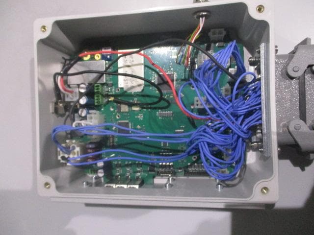
OQA-TX0N2BC0A3
Jul 09, 2026Transceiver unit
Equipment Class
DSS - Part 15 Spread Spectrum Transmitter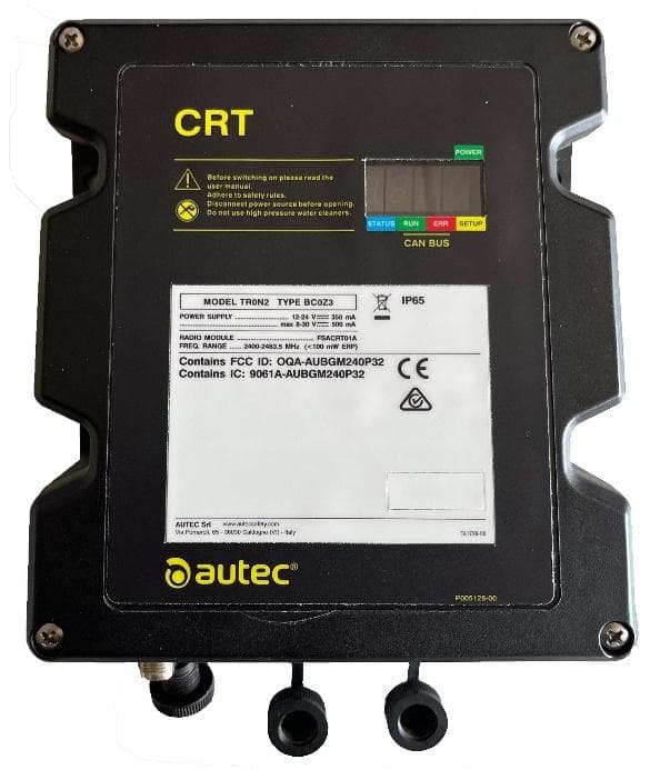
OQA-TR0N2BC0Z3
Jun 09, 2026Transceiver unit
Equipment Class
DSS - Part 15 Spread Spectrum Transmitter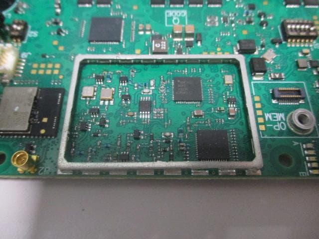
OQA-FSAACT01A
Mar 04, 2026Transceiver Unit
Equipment Class
DSS - Part 15 Spread Spectrum Transmitter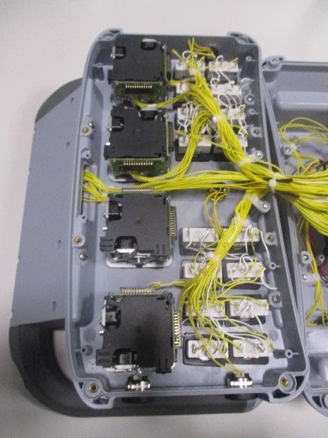
OQA-AX0A02Z0W1
Feb 24, 2026Transceiver Unit
Equipment Class
DSS - Part 15 Spread Spectrum Transmitter