OQA-RLBCA00MRemote Control - Fixed Unit
Autec s.r.l.
Click to zoom
Application Details
- Equipment Class
- DXT - Part 15 Low Power Transceiver, Rx Verified
- Date of Grant
- Dec 03, 2012
- Application Purpose
- Original Equipment
- Date of Application
- Dec 03, 2012
- Equipment Note
- Remote Control - Fixed Unit
- Frequency Range
- 915.00000000 - 928.00000000
- Company
- Autec s.r.l.
- Country
- Italy
Documents & Files
Document Text
Text extracted from the exhibit documents filed with the FCC. Open a document above to read the original.
Users Manual
Air series user manual A 0 L I B R 0 0 D 0 1 6 6 L I U A I R 1 A U 3 - 0 1 f l e x s a f e a r c h i t e c t u r e F S A 1 LIUAIR1AI3-01.fmAUTEC - Serie AIR INDICE 1 Descrizione radiocomando serie AIR ......................................................................................... 2 1.1 Funzionamento del radiocomando .......................................................................................... 2 1.2 Applicazioni ............................................................................................................................. 2 1.3 Dati tecnici .............................................................................................................................. 3 1.4 Funzione di sicurezza: protezione dell’arresto ........................................................................ 4 1.5 Protezione dai movimenti non voluti dalla posizione di riposo ................................................ 4 1.6 Identificazione del radiocomando ........................................................................................... 4 2 Conformità e frequenze ............................................................................................................... 4 2.1 Banda di frequenze 433.050-434.790 MHz ............................................................................ 4 2.2 Banda di frequenze 915-928 MHz .......................................................................................... 5 3 Valutazione dei rischi ................................................................................................................... 6 3.1 Valutazione dei rischi per macchine radiocomandate ............................................................. 6 3.2 Formazione del personale ...................................................................................................... 7 3.3 Condizioni lavorative ............................................................................................................... 7 4 Unità trasmittente A8 ................................................................................................................... 8 4.1 Descrizione unità A8 ............................................................................................................... 8 4.2 Funzionamento ....................................................................................................................... 8 4.3 Avvertenze per l’utilizzo ........................................................................................................ 10 4.4 Carica dell’unità A8 ............................................................................................................... 12 4.5 Docking station AIRDOCK01 ................................................................................................ 12 5 Unità ricevente ............................................................................................................................ 13 5.1 Descrizione unità ricevente G ............................................................................................... 13 5.2 Descrizione unità ricevente L ................................................................................................ 14 5.3 Funzionamento ..................................................................................................................... 14 5.4 Avvertenze per l’installazione ............................................................................................... 15 6 Batteria AIRBM3V7L ................................................................................................................... 17 6.1 Dati tecnici ............................................................................................................................ 18 6.2 Avvertenze per l’uso ............................................................................................................. 18 6.3 Rottamazione ........................................................................................................................ 19 7 Docking station ........................................................................................................................... 19 7.1 Collegamento tra docking station e alimentatore .................................................................. 20 8 Manutenzione del radiocomando .............................................................................................. 21 8.1 Manutenzione ordinaria ........................................................................................................ 21 8.2 Manutenzione straordinaria .................................................................................................. 23 8.3 Malfunzionamenti .................................................................................................................. 23 9 Manutenzione della macchina ................................................................................................... 25 10 Rottamazione .............................................................................................................................. 25 AUTEC - Serie AIR 2Descrizione radiocomando serie AIR Funzionamento del radiocomando 1 Descrizione radiocomando serie AIR 1.1Funzionamento del radiocomando Un radiocomando industriale è utilizzato per comandare macchine da posizione remota sen- za una connessione fisica (es. fili o cavi di collegamento) tra l’operatore e la macchina. Esso è costituito da un’unità trasmittente portatile da cui l’operatore comanda la macchina e da un’unità ricevente installata a bordo della macchina stessa. Le due unità comunicano tra loro in modo continuo tramite un collegamento radioelettrico. La ricerca di una frequenza libera a cui operare avviene automaticamente. Le due unità codificano i messaggi tramite un indirizzo unico (prodotto da Autec una sola vol- ta) e univoco (specifico per ogni radiocomando). 1.2Applicazioni Un radioc…
Text truncated - open the document above for the full version.
External Photos
Independent Testing Laboratory CMC Centro Misure Compatibilità S.r.l. Via dell’Elettronica, 12/C 36016 Thiene (VI) – ITALY Tel./Fax +39 0445 367702 www.cmclab.it - [email protected] Accredited by Ministry of Communications – Notified Body EMC Directive 2004/108/EC n° NB 2044 Page 1 of 2 EXTERNAL PHOTO Independent Testing Laboratory CMC Centro Misure Compatibilità S.r.l. Via dell’Elettronica, 12/C 36016 Thiene (VI) – ITALY Tel./Fax +39 0445 367702 www.cmclab.it - [email protected] Accredited by Ministry of Communications – Notified Body EMC Directive 2004/108/EC n° NB 2044 Page 2 of 2
ID Label/Location Info
RLB label position Labels_and_position_rlb_rev2.cdr RLB label and its dimension 6 0 , 0 m m 50,0 mm TA1129-01 A0TARG01P0875 RADIO MODULE TYPE: CA00M MODEL: RLB AIRRT32NM POWER SUPPLY 45-240V 50-60Hz max.....40-264V (0.4A) IC: 9061A-RLBCA00M FREQUENCY 433.050-434.790MHz N12335 FREQUENCY 915-928MHz FCC ID: OQA-RLBCA00M This radio device complies with Part 15 of the FCC Rules. Operation is subject to the following two conditions: (1) this device may not cause harmful interference, and (2) this device must accept any interference received, including interference that may cause undesired operation.
Internal Photos
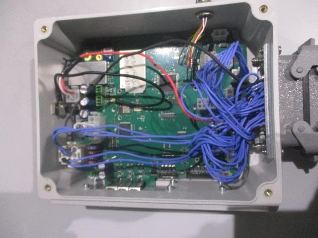
Independent Testing Laboratory CMC Centro Misure Compatibilità S.r.l. Via dell’Elettronica, 12/C 36016 Thiene (VI) – ITALY Tel./Fax +39 0445 367702 www.cmclab.it - [email protected] Accredited by Ministry of Communications – Notified Body EMC Directive 2004/108/EC n° NB 2044 Page 1 of 3 INTERNAL PHOTO Independent Testing Laboratory CMC Centro Misure Compatibilità S.r.l. Via dell’Elettronica, 12/C 36016 Thiene (VI) – ITALY Tel./Fax +39 0445 367702 www.cmclab.it - [email protected] Accredited by Ministry of Communications – Notified Body EMC Directive 2004/108/EC n° NB 2044 Page 2 of 3 Independent Testing Laboratory CMC Centro Misure Compatibilità S.r.l. Via dell’Elettronica, 12/C 36016 Thiene (VI) – ITALY Tel./Fax +39 0445 367702 www.cmclab.it - [email protected] Accredited by Ministry of Communications – Notified Body EMC Directive 2004/108/EC n° NB 2044 Page 3 of 3
Test Setup Photos
Independent Testing Laboratory CMC Centro Misure Compatibilità S.r.l. Via dell’Elettronica, 12/C 36016 Thiene (VI) – ITALY Tel./Fax +39 0445 367702 www.cmclab.it - [email protected] Accredited by Ministry of Communications – Notified Body EMC Directive 2004/108/EC n° NB 2044 Page 1 of 1 SETUP PHOTO
Contact Information
Applicant
Antonio Silvestri(Director)
Test Firm
CMC Centro Misure Compatibilit� srlBeghetto Renzo
Technical Specifications
| # | Rule Parts | Frequency Range | Power Output |
|---|---|---|---|
| 1 | 15C | 915 MHz - 928 MHz | - |
Other Applications from Autec s.r.l.
OQA-TM0N2EN0B3
Jul 20, 2026Transceiver Unit
Equipment Class
DSS - Part 15 Spread Spectrum Transmitter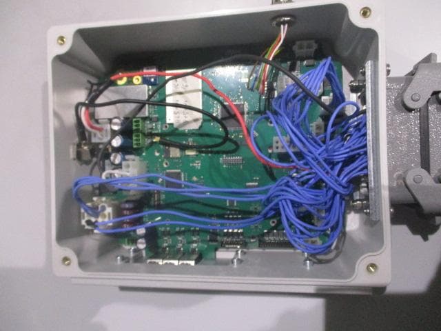
OQA-TX0N2BC0A3
Jul 09, 2026Transceiver unit
Equipment Class
DSS - Part 15 Spread Spectrum Transmitter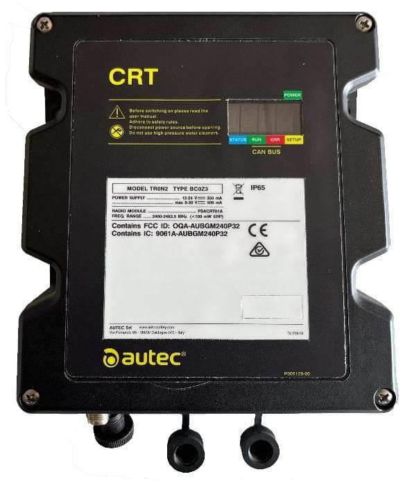
OQA-TR0N2BC0Z3
Jun 09, 2026Transceiver unit
Equipment Class
DSS - Part 15 Spread Spectrum Transmitter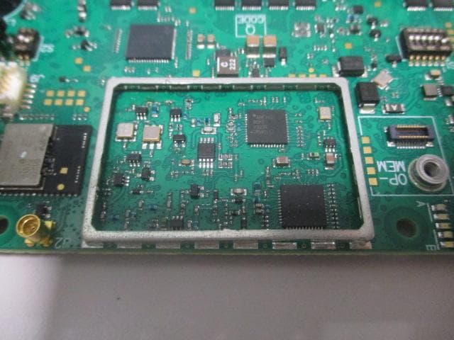
OQA-FSAACT01A
Mar 04, 2026Transceiver Unit
Equipment Class
DSS - Part 15 Spread Spectrum Transmitter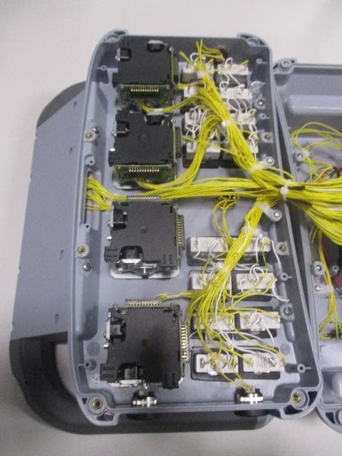
OQA-AX0A02Z0W1
Feb 24, 2026Transceiver Unit
Equipment Class
DSS - Part 15 Spread Spectrum Transmitter