OQA-TC02B03DRemote Control Transmitter TC02B03D
Autec s.r.l.
Click to zoom
Application Details
- Equipment Class
- DXX - Part 15 Low Power Communication Device Transmitter
- Date of Grant
- Sep 20, 2004
- Application Purpose
- Original Equipment
- Date of Application
- Sep 20, 2004
- Equipment Note
- Remote Control Transmitter TC02B03D
- Frequency Range
- 902.15000000 - 927.72500000
- Company
- Autec s.r.l.
- Country
- Italy
Documents & Files
Document Text
Text extracted from the exhibit documents filed with the FCC. Open a document above to read the original.
Users Manual
Transmitter System USER’S MANUAL Modular Series Follow the indications and warnings given by the machine producer regarding the machine controlled by the radio remote control. The information contained in this manual considers a representative configuration of the radio remote control: please find radio remote control real configuration in the technical data sheet (attached to the manual). If this manual is lost or damaged, ask for a copy from AUTEC. Please specify the serial number of the relative radio remote control. Contact AUTEC if any of the instructions and/or warnings given in this manual are not clear. The information contained in this manual is subject to modification without notice and is not binding. No parts of this manual may be reproduced by any means without the written permission of AUTEC (including recording and photocopying). LIMKPNA0 Page 1 THIS MANUAL REFERS EXCLUSIVELY TO THE TRANSMITTING UNIT: THE INSTALLATION WARNINGS ARE GIVEN IN THE RECEIVING UNIT MANUAL. BEFORE INSTALLING, STARTING AND USING THE RADIO REMOTE CONTROL, THIS MANUAL MUST BE READ AND UNDERSTOOD CAREFULLY BY ALL PEOPLE WHO INSTALL, USE AND CARRY OUT MAINTENANCE ON THE RADIO REMOTE CONTROL. Index and Conventions Introduction to Modular series MK10, MK12 transmitting unit Warnings for use Warnings for maintenance MK10, MK12 operation transmitting unit Frequencies Programming MK10, MK12 transmitting unit diagnostic 1 2 5 8 9 12 14 15 16 1 2 3 4 5 6 7 8 9 1 abcd. . . ! INDEX INDEX AND CONVENTIONS Page CONVENTIONS In this manual, all important information is indicated using the following symbols and conventions: : TECHNICAL DATA : IMPORTANT TEXTS abcd. . . abcd. . . : WARNINGS : INSTRUCTIONS abcd. . . Page 2 Each Modular series radio remote control complies with Part 15 of the FCC Rules. Operation is subject to the following two conditions: (1) this device may not cause harmful interference, and (2) this device must accept any interference received, including interference that may cause undesired operation. ! Changes or modifications not expressly approved by the party responsible for compliance could void the user’s authority to operate the equipment. LIMKPNA0 Industrial radio remote controls of the Modular series are used to command machines from a distance. Each industrial radio remote control is made up of a portable transmitting unit, from which the user can remotely control the machine, and a receiving unit installed on board the machine itself. The transmitting unit uses radio frequencies to transmit a coded message which contains a value called address. Each receiving unit can only decode the messages coming from a transmitting unit with the same address. This excludes the possibility of an interference activating any system function. If the radio frequency transmission is disturbed, incorrect or interrupted, the receiving unit autonomously stops the whole system. 2 INTRODUCTION TO MODULAR SERIES Receiving unit Transmitting unit Autec cannot be held responsible if the radio remote control is installed on applications that are different from those permitted PERMITTED USES Material lifting machines (construction cranes, industrial bridge cranes, machines for moving material in general, . . . ) FORBIDDEN USES Machines installed in areas where equipment with explosion-proof characteristics are being used. Machines for moving, raising and transporting people. : . ! Page 3 Alll machines must undergo a risk analysis; therefore it is necessary to evaluate, within the limits of this analysis, if the machine can be radio remote controlled. The machine producer and/or the person who decides upon radio remote control use and installation is responsible for this analysis. Autec cannot be held responsible if the risk analysis is not carried out correctly. To guarantee correct radio remote control operation, all current regulations regarding safety at work and accident prevention should be respected. All current user country national laws regarding the use of both the machine and the radio remote control MUST ALWAYS be respected. Autec cannot be held responsible if the radio remote control is used in unlawful working conditions. System must be installed by a licensed technician and in accordance with all relevant local, state/provincial and federal regulations, including but not limited to NEC, OSHA, CE etc. ! In any cases of emergencies, faults or damaged parts, ALWAYS stop the “machine + radio remote control” system until the problem has been solved. Any damaged parts can ONLY be replaced by authorised Autec personnel or service representative, and only using original Autec spare parts. LIMKPNA0 Page 4 The following minimum documentation is supplied with each radio remote control: - transmitting unit manual - receiving unit manual - battery charger manual - a guarantee certificate - the radio remote control technical data sheet. Make sure that the following documents have been supplied: if they are not, request them from Autec. Please specify the radio remote control serial number. The conditions of the radio remote control guarantee are given in the “Certificate of Guarantee”. The technical data sheet shows the wiring system between the receiving unit and the machine. It should be compiled and checked by the installer, who has the responsibility of correct wiring. Once all necessary checks have taken place the installer must sign the technical data sheet, which must be kept with the user's manual (always keep a copy of this data sheet in case it is needed for administrative purposes). The radio remote control identification and approval data is given on plates that are on both the transmitting unit and the receiving unit. The plates MUST NOT be removed from where they are placed or damaged otherwise the warranty will be forfeited. CERTIFICATE OF GUARANTEE TECHNICAL DATA SHEET IDENTIFICATION PLATES INSTRUCTIONS FOR DOCUMENT MANAGEMENT LIMKPNA0 902 - 928 MHz 32 ≥ 8 <10 exp-11 100 m <100 ms <100 ms * 0,35 / 1 se…
Text truncated - open the document above for the full version.
ID Label/Location Info
RADIO MODULE.............................................E16STXUS1 FREQUENCY RANGE....................................902-928MHz POWER SUPPLY................................MBM06MH 7,2V PROTECTION DEGREE..............................................IP65 TYPE TC02MODEL B03D Technical Data TRANSMITTER TA902/0 - A0TARG01P0664 ------ FCC ID: OQA-TC02B03D This radio device complies with Part 15 of the FCC Rules. Operation is subject to the following two conditions: (1) this device may not cause harmful interference, and (2) this device must accept any interference received, including interference that may cause undesired operation.
Operational Description
1 Operational Description for Type TC02 Model B03D transmitting unit Operational Description for Type TC02 Model B03D transmitting unit 1Identification of the unit where: TYPE: identifies type of unit (transmitting, receiving or transceiving), type of casing and used electronic modules. MODEL: differentiates power supply, type of actuators and radio frequency band CONFIGURATION: refersto the specific set of components and accessories of the unit TRADE NAME: commercial reference 2Operational description Industrial radio remote controls are used to command machines from a distance. Each industrial radio remote control is made up of a portable transmitting unit, from which the user can remotely control the machine, and a receiving unit installed on board the machine itself. The MK10 transmitting unit is a handheld unit. Ty p eTC02 ModelB03D ConfigurationP01 Equipmentremote control transmitting unit Trasmitting radio moduleE16STXUS1 Used frequency band902 - 928 MHz Trade nameMK10 FCC IdentifierOQA-TC02B03D Manufacturer AUTEC srl Via Pomaroli, 65 I-36030 CALDOGNO (VI) Receiving unit Transmitting unit 2 Operational Description for Type TC02 Model B03D transmitting unit The MK10 contains E16STXUS1. It is the radio transmitting module. A logic section collects commands coming from various actuators (switches and or pushbut- tons in the E16STI102 keyboard) and combines them with an address code stored an EEPROM memory ("address Key"); a serial data telegram at 2200-2600 baud is so obtained. After a Gaussian spectrum shaping filter, the telegram is frequency modulated on a carrier generated by a PLL synthesizer and then trasmitted over a 25kHz channel in the 902-828 MHz band; 32 different frequencies my be chosen, so as to allow cohexistence of multiple units on the same location (for details see relative block diagrams). Transmission is continuous (100% duty cycle) even with no command activated, since the reciver is expected to monitor continuously the presence of a valid radio signal. A receiving unit will decode only messages coming from a transmitter with the same address code. This excludes the possibility of an interference activating any function unwantedly. 3Exploded view STOP pushbutton Casing E16STXUS1 transmitting module (contains encoder and radio transmitter) Toggle switch Pushbutton Keyswitch selector for powering the unit Pushbutton for starting the unit keyboard grid E16STI102 keypad (contains the key actuators and their wiring) Keyswitch selector Address key (contains the address of the telegram) 3 Operational Description for Type TC02 Model B03D transmitting unit 4Technical data E16STXUS1 trasmitting radio module 5Power supply: MBM06MH battery pack MBM06MH batteries must only be recharged using MBC____ battery chargers. Use the battery until it is totally discharged (the led of the transmitting unit flashes quickly when the battery used is discharged). Used frequency band902 - 928 MHz Type of modulation2200 - 2600 Baud GFSK Channel spacing25 kHz Designation of emission (ITU code)16K5F1D Strenght fieldsee relative Test Report Duty cycle up to 100 % (continuous duty), depends on user’s need Duplex directionsimplex Antenna typededicated Data telegram132 bit Hamming distance> 8 Probability of non-recognition of error<10 exp-11 number of NiMH elements6 nominal voltage of 1 element (V)1,2 total nominal voltage of the battery (V)7,2 battery voltage after discharge (V)6 voltage of the charged battery (V)8,4 capacity (mAh)750 number of cycles in average life400 autonomy (hours)up to 15 recharge time (approx) 3 4 Operational Description for Type TC02 Model B03D transmitting unit
Test Report
FCC.TR. TEST REPORT 04.199 Prima Ricerca & Sviluppo Srl soggetta a direzione e coordinamento da parte della Giovanni Maspero & C. S.p.A. – C.I. 02634780130 Sede legale : 22100 Tavernola (CO) Via Conciliazione, 1 Cod. FISC. e N. R.I. CO 02635860139 Sede operativa : Laboratori Via Campagna, 92 22020 Faloppio fraz. Gaggino (CO) Tel. +39 03135000.11 Fax +39 031991309 Edition: 1.1 Issue date: 13/07/04 sheet 1 of 25 EQUIPMENT UNDER TEST : APPARECCHIO IN PROVA : MK10 Handheld transmitting unit (10 keys) Type TC02 Model B03D Configuration P01 REFERENCE STANDARDS : NORME DI RIFERIMENTO : FCC 47 CFR Part 15 CUSTOMER: RICHIEDENTE: • Dept. / Firm : Ente / Società’: AUTEC S.r.l. • Mr.: Sig.: BIANCHIN STEFANO • Address: Indirizzo: VIA POMAROLI, 65 - 36030 CALDOGNO (VI) - ITALY • Tel. : Telefono : ++39 0444 901000 • Telefax Fax : ++39 0444 901080 • E-mail: e-mail [email protected] Site of test execution: Via Campagna, 92 - 22020 Gaggino Faloppio (CO) - Italy Località esecuzione prove: Date of test samples receipt: 26/05/04 Date of start test: 28/05/04 Data ricevimento campioni: Data inizio prove: Date of end test: 10/06/04 Data fine prove: Witness to the test: Presenti alle prove: Signature of the engineers: Firma esecutore prove: Signature of the Laboratory Director: Firma Direttore Laboratori: Nobody / Nessuno ......................................................... .......................................................... F. Barbierato .......................................................... R. Furfari The test results recorded in this Test Report are exclusively referred to the tested samples. I risultati del presente rapporto di prova si riferiscono esclusivamente al campione sottoposto a prova. Reproduction of this EMC-Test Report in whole or in part is prohibited without the written authorization of the Laboratory Director La riproduzione di questo Rapporto in modo parziale o totale è PROIBITO senza l’autorizzazione scritta della Direzione del Laboratorio FCC.TR. TEST REPORT 04.199 Prima Ricerca & Sviluppo Srl soggetta a direzione e coordinamento da parte della Giovanni Maspero & C. S.p.A. – C.I. 02634780130 Sede legale : 22100 Tavernola (CO) Via Conciliazione, 1 Cod. FISC. e N. R.I. CO 02635860139 Sede operativa : Laboratori Via Campagna, 92 22020 Faloppio fraz. Gaggino (CO) Tel. +39 03135000.11 Fax +39 031991309 Edition: 1.1 Issue date: 13/07/04 sheet 2 of 25 0. CONTENTS Page Rev Date 0. CONTENTS ................................................................................................. 1. TECHNICAL INFORMATION OF EQUIPMENT UNDER TEST (EUT) ........ 1.1 Identification ......................................................................................... 1.2 Technical data ...................................................................................... 1.3 Transmitter technical data ................................................................... 1.4 Modifications incorporated in E.U.T...................................................... 1.5 Ports identification ................................................................................ 1.6 Auxiliary equipment .............................................................................. 2. TEST CONDITIONS .................................................................................... 2.1 Operating test modes and test conditions ............................................ 2.2 Test overview ....................................................................................... 3. REFERENCE STANDARD FOR PERFORMED TESTS ............................. 4. Summary of test results ............................................................................... 4.1 Tests..................................................................................................... 4.2 Emission limits...................................................................................... 5. TEST RESULTS .......................................................................................... 6. EUT TECHNICAL DOCUMENTATION........................................................ 6.1 Wiring diagrams.................................................................................... 6.2 Technical manual ................................................................................. 6.3 Photographic documentation ................................................................ 0 0 0 0 0 0 0 0 0 0 1 0 0 1 1 1 0 0 0 0 10/07/04 10/07/04 10/07/04 10/07/04 10/07/04 10/07/04 10/07/04 10/07/04 10/07/04 10/07/04 10/07/04 10/07/04 10/07/04 10/07/04 10/07/04 10/07/04 10/07/04 10/07/04 10/07/04 10/07/04 FCC.TR. TEST REPORT 04.199 Prima Ricerca & Sviluppo Srl soggetta a direzione e coordinamento da parte della Giovanni Maspero & C. S.p.A. – C.I. 02634780130 Sede legale : 22100 Tavernola (CO) Via Conciliazione, 1 Cod. FISC. e N. R.I. CO 02635860139 Sede operativa : Laboratori Via Campagna, 92 22020 Faloppio fraz. Gaggino (CO) Tel. +39 03135000.11 Fax +39 031991309 Edition: 1.1 Issue date: 13/07/04 sheet 3 of 25 1. TECHNICAL INFORMATION OF EQUIPMENT UNDER TEST (EUT) 1.1 Identification Brand name: AUTEC Equipment : MK10 handheld unit (10 keys) Model name or No. : Type TC02 Model B03D Serial number : prototype FCC ID : OQA-TC02B03D Country of manufacturer: ITALY 1.2 Technical data FCC class: Intentional Radiators TX module type : E16STXUS1 Supply voltage: Custom NiMH Battery pack 7,2 Vdc 750mAh model MBM06MH Typical usage : Portable radio remote control used to command Industrial machines EUT single or system: Single EUT dimensions : 270 x 95 x 50 mm FCC.TR. TEST REPORT 04.199 Prima Ricerca & Sviluppo Srl soggetta a direzione e coordinamento da parte della Giovanni Maspero & C. S.p.A. – C.I. 02634780130 Sede legale : 22100 Tavernola (CO) Via Conciliazione, 1 Cod. FISC. e N. R.I. CO 02635860139 Sede operativa : Laboratori Via Campagna, 92 22020 Faloppio fraz. Gaggino (CO) Tel. +39 03135000.11 Fax +39 031991309 Edition: 1.1 Issue date: 13/07/04 sheet 4 …
Text truncated - open the document above for the full version.
Contact Information
Applicant
Antonio Silvestri(Director)
Test Firm
Prima Ricerca & Sviluppo S.r.l.Enrico Banfi
Technical Specifications
| # | Rule Parts | Frequency Range | Power Output |
|---|---|---|---|
| 1 | 15C | 902.15 MHz - 927.725 MHz | - |
Other Applications from Autec s.r.l.
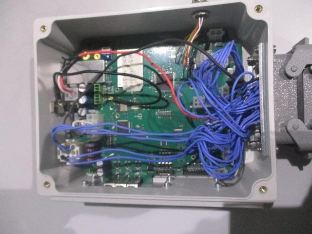
OQA-TM0N2EN0B3
Jul 20, 2026Transceiver Unit
Equipment Class
DSS - Part 15 Spread Spectrum Transmitter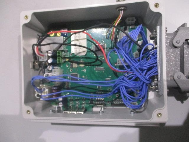
OQA-TX0N2BC0A3
Jul 09, 2026Transceiver unit
Equipment Class
DSS - Part 15 Spread Spectrum Transmitter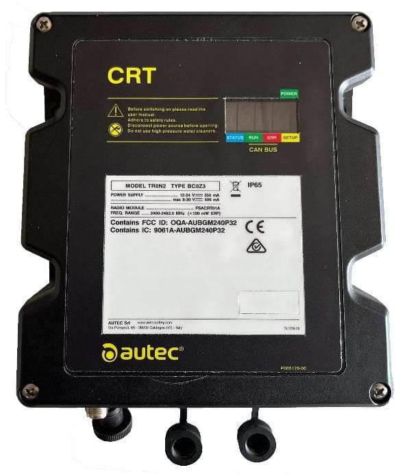
OQA-TR0N2BC0Z3
Jun 09, 2026Transceiver unit
Equipment Class
DSS - Part 15 Spread Spectrum Transmitter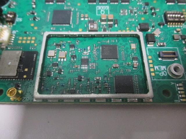
OQA-FSAACT01A
Mar 04, 2026Transceiver Unit
Equipment Class
DSS - Part 15 Spread Spectrum Transmitter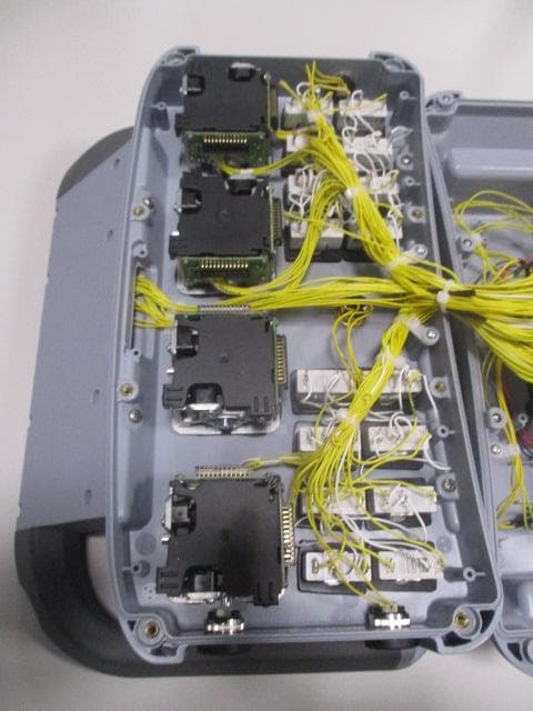
OQA-AX0A02Z0W1
Feb 24, 2026Transceiver Unit
Equipment Class
DSS - Part 15 Spread Spectrum Transmitter