OQAMTXUS04AHand-held remote control transmitter
Autec s.r.l.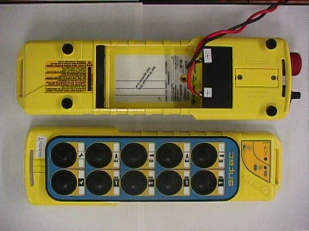
Click to zoom
Application Details
- Equipment Class
- TNB - Licensed Non-Broadcast Station Transmitter
- Date of Grant
- Jan 18, 2000
- Application Purpose
- Original Equipment
- Date of Application
- Sep 29, 1999
- Equipment Note
- Hand-held remote control transmitter
- Frequency Range
- 450.00000000 - 470.00000000
- Company
- Autec s.r.l.
- Country
- Italy
Documents & Files
Document Text
Text extracted from the exhibit documents filed with the FCC. Open a document above to read the original.
Users Manual
- 1 - Important Notice Read this instruction manual carefully before using the system. All operations related to the installation, use and maintenance of the system must be restricted to authorised personnel. Contents of this Manual This documentation has been compiled by Autec with the aim of providing the operator with all the information necessary for the use and maintenance of the radio remote control. IDENTIFICATION OF THE RADIO REMOTE CONTROL The Radio remote control identification data can be found on the plates affixed to the Transmitter and the Receiver. Wichtiger Hinweis Bevor die Anlage in Betrieb genommen wird, muß die vorliegende Betriebsanleitung aufmerksam gelesen werden, um sich mit der Anlage vertraut zu machen. Alle Installations-, Bedien- und Wartungsarbeiten dürfen ausschließlich von autorisiertem und geschultem Personal durchgeführt werden. Inhalt der vorliegenden Betriebsanleitung Diese Betriebsanleitung ist von der Firma Autec mit dem Ziel erstellt worden, dem Benutzer alle notwendigen Angaben für die Montage, die Bedienung und die Wartung der Funkfernsteuerung zu geben. Kennzeichnung der Funkfernsteuerung Die Kennzeichnung der Funkfernsteuerung befindet sich beim Sender auf dem Typenschild unter dem Akku und beim Empfänger auf dem Typenschild auf dem Gehäusedeckel. D E U T S C H F R A N Ç A I S Important! Lire attentivement ce manuel avant de faire fonctionner votre appareil. Veiller à ce que toutes les opérations d'installation, d'utilisation et d'entretien soient toujours effectuées par un personnel habilité à réaliser ces travaux. Contenu du présent manuel Ce manuel a été réalisé par la société Autec dans le but d'apporter une aide efficace dans l'entretien et le fonctionnement de la radiocommande. IDENTIFICATION DE LA RADIOCOMMANDE Les références de la radiocommande sont mentionnées sur la plaque d'identification tant de l'émetteur que du récepteur. Avvertenza Importante Prima di mettere in funzione l'impianto leggere attentamente il presente manuale. Tutte le operazioni d'installazione, uso e manutenzione devono tassativamente essere precluse a per- sonale non autorizzato. Contenuto del presente manuale Questa documentazione é stata redatta dalla ditta Autec con l'obiettivo di fornire all'operatore tut- te le indicazioni necessarie per l'uso e la manutenzione del Radiocomando. IDENTIFICAZIONE DEL RADIOCOMANDO I dati di identificazione del Radiocomando sono riportati su apposita targhetta sia sull'Unità Tra- smittente che sull'Unità Ricevente. I T A L I A N O E N G L I S H LIPRO0U1 ENGLISHDEUTSCH - 2 - CONTENTS 1.0CONFORMITY ....................................................................... 3 2.0CONVENTIONS ...................................................................... 3 3.0GENERAL DESCRIPTION .................................................... 3 4.0CORRECT AND SAFE USE OF THE RADIO REMOTE CONTROL .............................................................. 4 4.1APPLICATIONS.................................................................... 4 4.2PROHIBITED APPLICATIONS........................................... 4 4.3THE OPERATOR OF THE RADIO REMOTE CONTROL................................ 4 4.4OPERATOR TRAINING ........................................................ 5 5.0INSTALLATION.................................................................... 5 6.0OPERATING INSTRUCTIONS ............................................ 8 6.1BATTERY ................................................................................ 8 6.2TRANSMITTER..................................................................... 9 6.3RECEIVER............................................................................. 11 6.4BATTERY CHARGER ......................................................... 13 7.0SELECTING THE OPERATING FREQUENCY ................. 13 8.0PREVENTIVE MAINTENANCE ......................................... 13 9.0INSTRUCTIONS TO FOLLOW IN CASE OF SYSTEM FAILURE....................................... 14 10.0SERVICE................................................................................ 15 11.0WARRANTY........................................................................ 15 12.0DISPOSAL OF UNWANTED PRODUCTS....................... 15 13.0WEIGHTS AND DIMENSIONS......................................... 15 14.0TECHNICAL DATA............................................................ 16 * TECHNICAL DATA SHEET FOR RADIO REMOTE CONTROL ATTACHED INHALTSVERZEICHNIS 1.0KONFORMITÄT.................................................................... 3 2.0ERLÄUTERUNGEN ............................................................... 3 3.0ALLGEMEINE BESCHREIBUNG ......................................... 3 4.0HINWEISE FÜR DIE KORREKTE UND SICHERE VERWENDUNG DER FUNKFERNSTEUERUNG ............... 4 4.1ANWENDUNGEN .................................................................. 4 4.2NICHT ZUGELASSENE ANWENDUNGEN ....................... 4 4.3DER BEDIENER DER FUNKFERNSTEUERUNG ..................................................... 4 4.4SCHULUNG DER BEDIENER............................................... 5 5.0MONTAGE UND INBETRIEBNAHME ............................... 5 6.0ANGABEN UND BEDIENUNGSANWEISUNGEN ............ 8 6.1AKKUS.................................................................................... 8 6.2SENDER................................................................................... 9 6.3EMPFÄNGER ........................................................................ 11 6.4AKKULADEGERÄT ............................................................ 13 7.0ARBEITSFREQUENZEN ..................................................... 13 8.0PRÄVENTIVWARTUNG .................................................... 13 9.0STÖRUNGEN ........................................................................ 14 10.0KUNDENDIENST ................................................................. 15 11.0GARANTIE ..............................................................…
Text truncated - open the document above for the full version.
Cover Letter(s)
Agent Authorization Autec S.r.l. hereby authorizes MET Laboratories, Inc. to act on our behalf before the Federal Communications Commission in matters concerning equipment authorizations. Any and all acts carried out by MET Laboratories, Inc. shall have the same effect as acts of our own. Further, Autec S.r.l. certifies that no party to the application is subject to a denial of federal benefits, that includes FCC benefits, pursuant to Section 5301 of the Anti-Drug Abuse Act of 1988, 21 U.S.C. 853(a). For the definition of a “party” for these purposes, see 47 CFR 1.2002(b). This authorization expires one year the date of this letter. Dated: 13/09/99 By: ____________________________Antonio Silvestri Title: Technical DirectorTelephone Number in Italy: 00-39-0444-901000
Cover Letter(s)
Federal Communications Commission 7435 Oakland Mills Road Columbia, MD 21046 re: CONFIDENTIALITY request for FCC ID:***MTXUS04A ***MTXUS03A ***MRXUS03A Dear Sir/Madam, Autec S.r.l. hereby requests that the ( item(s): schematics, parts list, or particular photos of internal circuitry ) be held as confidential items per FCC Rule Section 0.459. This request is based on the fact that there is proprietary operational and configuration information contained in the specified item(s). Release of these items to the general public, and thus our competition, would be detrimental to our competitive edge. Sincerely, Dated: 13/09/99 Autec S.r.l. Technical Director - Antonio Silvestri
Cover Letter(s)
1 Federal Communications Commission 7435 Oakland Mills Road Columbia, MD 21046 re: CONFIDENTIALITY request for FCC ID: OQAMTXUS04A Dear Sir/Madam, Autec S.r.l. hereby requests that the ( item(s): schematics and parts list )be held as confidential items per FCC Rule Section 0.459. This request is based on the fact that there is proprietary operational and configuration information contained in the specified item(s). Release of these items to the general public, and thus our competition, would be detrimental to our competitive edge. Sincerely, Dated: 21/10/99 Autec S.r.l. Technical Director - Antonio Silvestri 2 Federal Communications Commission 7435 Oakland Mills Road Columbia, MD 21046 re: CONFIDENTIALITY request for FCC ID: OQAMTXUS03A Dear Sir/Madam, Autec S.r.l. hereby requests that the ( item(s): schematics and parts list ) be held as confidential items per FCC Rule Section 0.459. This request is based on the fact that there is proprietary operational and configuration information contained in the specified item(s). Release of these items to the general public, and thus our competition, would be detrimental to our competitive edge. Sincerely, Dated: 21/10/99 Autec S.r.l. Technical Director - Antonio Silvestri
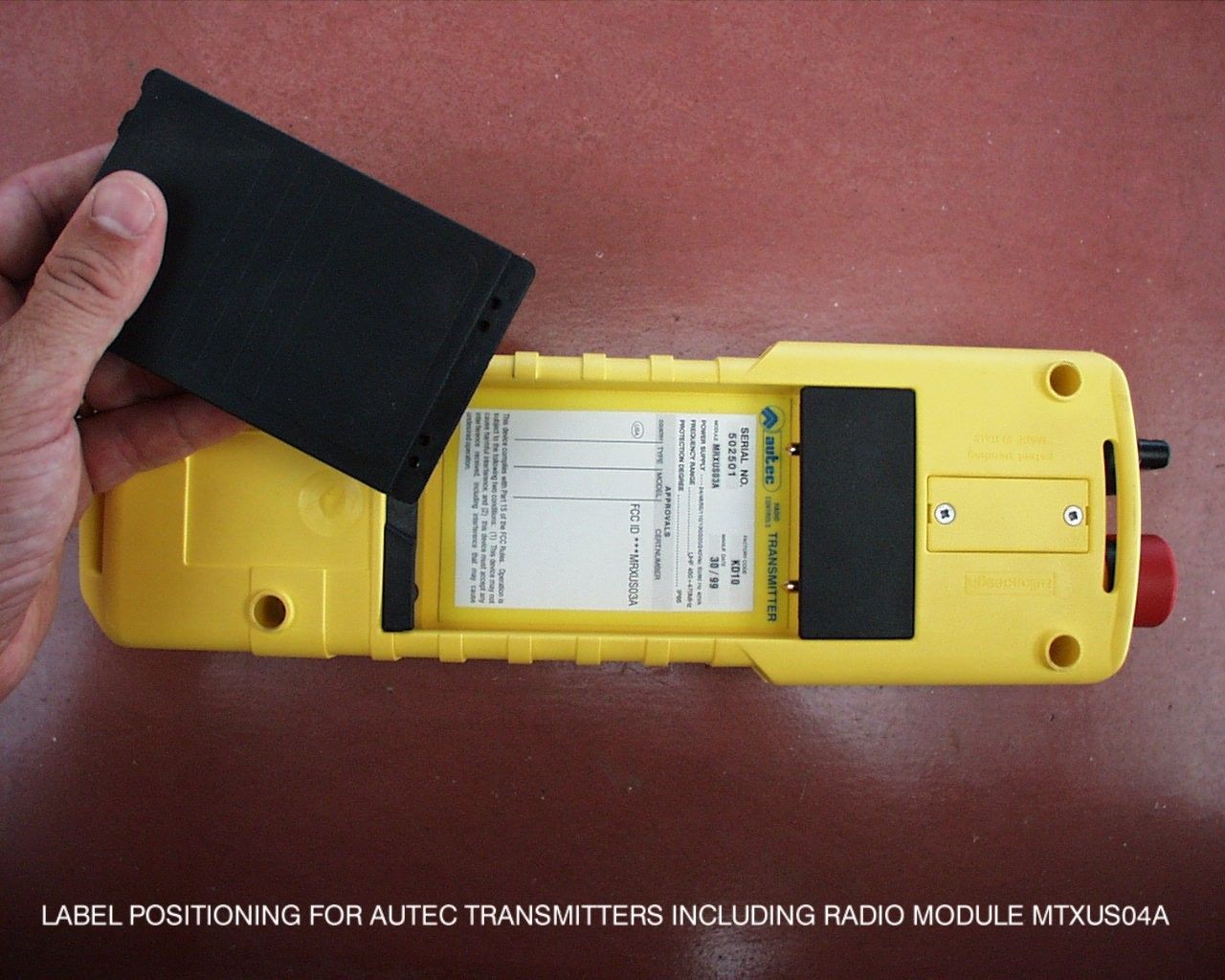
ID Label/Location Info
Descrizione: / // LabelpositioningMTXUS03A,MTXUS04A,MRXUS03A / / / / / / / 15/09/99/ Codice: Cod.Prec.: Disegnato: Richiesto: Materiale: Spessore: Toll. Approvato: Data: Rev.0 Documento:LABEL.CDR Scala: Verificato: Anormedileggeèvietatalariproduzioneolaconsegnaaterzidelpresentedisegnosenzanostraautorizzazionescritta. ViaPomarolin.9,36030Caldogno(VI) Tel.0444/901000r.a.-Fax0444/901011 UHF450÷470MHz UHF450÷470MHz IP65 IP65 Ni-Cd7,2V-0,7Ah : : SERIALNO. SERIALNO. FREQUENCYRANGE FREQUENCYRANGE APPROVALS APPROVALS FACTORYCODE FACTORYCODE PROTECTIONDEGREE PROTECTIONDEGREE MODEL MODEL CERT.NUMBER CERT.NUMBER MANUF.DATE MANUF.DATE COUNTRY COUNTRY POWERSUPPLY POWERSUPPLY TYPE TYPE MODULE MODULE 502501 502501 MD22 KD10 30/99 30/99 MTXUS03A MTXUS04A USA USA RFOUTPUTPOWER <20mWERP RFOUTPUTPOWER <20mWERP Ni-Cd7,2V-0,7Ah ThisdevicecomplieswithPart15oftheFCCRules.Operationis subjecttothefollowingtwoconditions:(1)Thisdevicemaynot causeharmfulinterference,and(2)thisdevicemustacceptany interferencereceived,includinginterferencethatmaycause undesiredoperation. ThisdevicecomplieswithPart15oftheFCCRules.Operationis subjecttothefollowingtwoconditions:(1)Thisdevicemaynot causeharmfulinterference,and(2)thisdevicemustacceptany interferencereceived,includinginterferencethatmaycause undesiredoperation. FCCID***MTXUS04AFCCID***MTXUS03A
Operational Description
pag.14 di 27 PT0023US.P65 T R A N S M I T T E R MTXUS04A NORMATIVE REFERENCE............................................................................................................................................ FCC part 90 TYPE OF EQUIPMENT......................................................TRANSMITTER WITH INTEGRAL OR DEDICATED ANTENNA (simplex) FREQUENCY CHARACTERISTICS...............................................................................................SYNTHESIZER (REF. 12.8 MHz) ALIGNMENT RANGE (AR1)...................................................................................................................................UHF 450-470 MHz SWITCHING RANGE................................................................................................................................. ANY 3.2 MHz SUB BAND CHANNEL SEPARATION*.................................................................................................................................................... 12.5 kHz MAXIMUM NUMBER OF CHANNELS........................................................................................................................................... 256 POWER LEVEL RADIATED (class IA) ..................................................................................................................... ≤ 20 mW ERP TYPE OF MODULATION (digital)*.................................................................................................................. GFSK (FFSK optional) MODULATION BIT RATE*........................................................................................ standard 4.800bit/s (up to 19.200 bit/s optional) MAXIMUM FREQUENCY DEVIATION*.............................................................................................................................. +/- 2.5 kHz EXTREME TEMPERATURE RANGE (category 1)..................................................................................................... -20º C ÷ +55º C NOMINAL SOURCE VOLTAGE.................................................................................................................................................... 6 V EXTREME SOURCE VOLTAGES....................................................................................................................................... 5.6 ÷ 15 V DC MAXIMUM CURRENT.....................................................................................................................................................≤ 60 mA FREQUENCY ERROR ........................................................................................................................................................ +/- 1 kHz ADIACENT CHANNEL POWER* (class IA) ...................................................................................................................... ≤ 200 nW POWER SPURIOUS EMISSIONS (conducted or radiated) FREQUENCY RANGE 47÷74MHz, 87,5÷118MHz, 174÷230MHz, 470÷862MHz.................................................................... < 4 nW FREQUENCY RANGE < 1GHz .......................................................................................................................................... < 250 nW FREQUENCY RANGE > 1GHz .............................................................................................................................................. < 1 μW DIMENSIONS...........................................................................................................................................................SEE DRAWING * THESE VALUES ARE MEASURED AT STANDARD BIT RATE (4800 bit/s), WHEN EMPLOYING GFSK MODULATION AND WIDE BAND CHANNEL SPACING, IT IS POSSIBLE TO OPERATE THE RADIO MODULE AT BIT RATES UP TO 19200 bits/s pag.15 di 27 PT0023US.P65 Functional description of MTXUS04A radio transmitter module The module is a PLL synthesized digital data transmitter, operating in the 450-470 ISM band as a lower power device (20 mW ERP). Two-point PLL frequency modulation, with an input bandwidth from 0.5 to 10000 Hz, allows for the implementation of any frequency-shift keying (F1D) or subcarrier FM (F2D) modulation scheme; for example, if a gaussian-filtered 4800 bps data stream of 1Vpp is applied to the modulation input, a narrow band Gaussian FSK (∆f=±2400 Hz) is obtained which is compatible with 12.5 kHz channel spacing. Alternatively, a 1 Vpp subcarrier at 1800 Hz, MSK modulated at 2400 Baud, could be used on the same 12.5 kHz channel. The carrier frequency is generated by a Voltage Controlled Oscillator (VCO, Q4, Q5), which is phase locked to a 12. 8 MHz ±2.5ppm reference frequency Voltage Controlled Temperature Compensated Xtal Oscillator (VCTCXO, U3). The PLL frequency synthesizer (U1) is programmed by a microcontroller (U5), which reads default data from an EEPROM (U2) and user data from a dip-switch; a low-pass filter, driving the control input of the VCO (DV1, DV2), closes the PLL feedback loop. The signal coming from the VCO is amplified by Q6 and Q7; the correct 20mW output power level can be adjusted by P1. Before reaching the antenna, the RF passes through a fifth order low-pass filter (L8, L9, C52, C56, C57), in order to prevent the harmonics to be radiated. The modulating signal is bufferd and splitted into two paths (U2, P2, P3), in order to obtain a balanced effect from the in- loop (DV3 on VCO) and out-of-loop (VCTCXO freq. adj. Input) modulation points. This modulation technique overrides the high-pass effect encountered when only the VCO is modulated, giving a FM characteristic which is linear down to d.c. and allows for clean digital frequency keying. The power supply is regulated to 5V by U6, a low-drop out device.The microprocessor inhibits the 5V line of the RF power amplifier when the PLL is out of lock, in order to avoid radiating high-level RF signals outside the permitted band. A PTT line can reduce the output power to by 30-40 dB, when needed. A SETUP signal can shift theoutput frequency b…
Text truncated - open the document above for the full version.
Test Report
FCC ID:OQAMTXUS04A October 12, 1999 Federal Communications Commission Authorization and Evaluation Division 7435 Oakland Mills Road Columbia, MD 21046 Attention:Applications Examiner Applicant:AUTEC s.r.l. 36030 Caldogno (VI) via Pomaroli 9 Italy Equipment: FCC ID: Specification:47 CFR 90 Licensed Certification Dear Examiner: The following application for Grant of Equipment Authorization is presented on behalf of AUTEC s.r.l. for the Licensed Certification of their Model: MTXUS04A, Transmitter Radio Module. Enclosed, please find a complete data and documentation package demonstrating that this device complies with the technical requirements of 47 CFR 90, for a Transmitter Radio Module. If you have any questions, please contact the undersigned, who is authorized to act as Agent. Sincerely, Chris Harvey Director, EMC Laboratory FCC ID:OQAMTXUS04A EMI1229A- 2 -October 12, 1999 MET Laboratories, Inc. Safety Certification - EMI - Telecom Environmental Simulation 914 WEST PATAPSCO AVENUE !! BALTIMORE, MARYLAND 21230-3432 !! PHONE (410) 354-3300 !! FAX (410) 354-3313 ENGINEERING TEST REPORT in support of the Application for Grant of Equipment Authorization EQUIPMENT:Transmitter Radio Module MODEL: MTXUS04A FCC ID: Specification:47 CFR 90 On Behalf of the Applicant:AUTEC s.r.l. 36030 Caldogno (VI) via Pomaroli 9 Italy Manufacturer:AUTEC s.r.l. 36030 Caldogno (VI) via Pomaroli 9 Italy Manufacturer’s Antonio Silvestri Representative Test Date(s):June 29, 1999 through July 12, 1999 ENGINEERING STATEMENT I ATTEST: the measurements shown in this report were made in accordance with the procedures indicated, and that the emissions from this equipment were found to be within the limits applicable. I assume full responsibility for the accuracy and completeness of these measurements. On the basis of the measurements made, the equipment tested is capable of operation in accordance with the requirements of Part 90 of the FCC Rules under normal use and maintenance. _____________________________ Andrew Leimer EMI Engineer, MET Laboratories FCC ID:OQAMTXUS04A EMI1229A- 3 -October 12, 1999 1.0INTRODUCTION The following data is presented on behalf of the Applicant, AUTEC s.r.l., as verification of the compliance of the AUTEC Transmitter Radio Module, Model MTXUS04A to the requirements of 47 CFR 90. 2.0TEST SITE All testing was conducted at MET Laboratories, Inc., 914 West Patapsco Avenue, Baltimore, Maryland 21230-3493. Radiated emissions measurements were performed on a three-meter open area test site (OATS). A complete site description is on file with the FCC Laboratory Division as 31040/SIT/MET. 3.0TEST EQUIPMENT USED ManufacturerEquipment Calibration DueCal. Interval Hewlett Packard8563A Spectrum Analyzer5/22/00annual EMCOBiconical Antenna 31043/9/00annual EMCOEMCO Log Periodic Antenna2/16/00annual EMCODouble Ridge Guided Horn2/8/00annual Hewlett Packard8594EM Analyzer11/18/99annual 4.0EQUIPMENT UNDER TEST CONFIGURATION The Equipment Under Test (EUT) was a Transmitter Radio Module MODEL: MTXUS04A. It is a radio signal transmitter with no external ports and was configured with the transmitter which modulates the carrier continually transmitting secure codes to establish communications with the receiver. 5.0TEST TYPE(S) 5.1Field Strength of Spurious Radiation: 47 CFR 2.1053, 15.209, 15.205, 90.217, 90.210 (d) 5.2Occupied Bandwidth: 47 CFR 2.1049, 2.1047, 90.211, 90.217, 90.210 (d) 5.3RF Power Output: 47 CFR 2.1046, 90.217 5.4Spurious Emission at Antenna Terminals: 47 CFR 2.1051, 90.217, 90.210(d) 5.5Frequency Stability Over Temperature Variations: 47 CFR 2.1055, 90.213 (a) Footnote 8 5.6Frequency Stability Over Voltage Variations: 47 CFR 2.1055 (d) (2), 90.213 (a) Footnote 8 5.7Requirements for Exempt Transmitters: 47 CFR 90.217 (b) E(V/m) 1m ' 49.2X0.120 1 E(V/m) 1m '2.4298V/mor127.71dbμV 50%10Log(0.120)'40.792dB 127.71dBμV&40.79dB'86.92dBμV@1m E(V/m) 3m ' 49.2X0.120 3 E(V/m) 3m '0.80994V/mor118.17dbμV 118.169&40.79'77.38dBμV@3m FCC ID:OQAMTXUS04A EMI1229A- 4 -October 12, 1999 6.0TEST RESULTS 6.1TEST TYPE: Field Strength of Spurious Radiation 6.1.1TECHNICAL SPECIFICATION:2.1053, 15.209, 15.205, 90.217, 90.210 (d) 6.1.2TEST DATE(S):July 7, 1999 6.1.3MEASUREMENT PROCEDURES: As required by 47 CFR 2.993,Field Strength of Spurious Radiation measurements were made in accordance with the general procedures of ANSI C63.4-1992 "Methods of Measurement of Radio-Noise Emissions from Low-Voltage Electrical and Electronic Equipment in the Range of 9kHz to 40 GHz". Preliminary radiated emission measurements were performed inside a shielded chamber with all digital signal generators on and terminated. The frequency list from the preliminary measurements was used as a guide for making final measurements on a 3 meter open area test site. The unit was scanned over the frequency range of 9 kHz to 5 GHz. The Field Strength of Spurious Radiation Limit is obtained by the following: Based on an output power (assuming the minimum power for non-exempt transmitters) of 120 mW: P = 120 mW o As per 2.1051 (a), it is assumed this power is to be fed to a half-wave tuned dipole. Using a conversion formula for distance, the field strength at one meter can be derived: As per 90.210 (d), the spurious emissions must be attenuated by 50 + log(P) which is: Therefore, the limit for spurious emissions is: At 3 meters measurement distance, the limit is; According to 24.238(a), all signals must be attenuated by 40.792 dB. Therefore, the limit for spurious emissions for a test distance of 3 meters is: FCC ID:OQAMTXUS04A EMI1229A- 5 -October 12, 1999 6.1.4RESULTS: Frequency AzimuthPola-HeightRawAnt.Cor.CableOtherCorrectedLimit (MHz)(EECCW-rity(m)AmplitudeFactorLoss1m toAmplitude(dBuV/m) OEE=EUT(dBuV)(db)(db)3m(dBuV/m)at 10 meters facing ant.) 453.28790H1.892.017.64.43114.0118.2 453.287160V2.080.517.14.43102.0118.2 906.575180H2.014.825.86.6347.277.4 906.575180V2.015.824.56.6346.977.4 1359.8600H1.019.523.51.0144.087.0 1359.8600V1.027.823.51.0152.387.0 18…
Text truncated - open the document above for the full version.
Contact Information
Applicant
Antonio Silvestri(Director)
Technical Contact
MET Laboratories, Inc.Chris R Harvey
[email protected]410-354-3300
914 West Patapsco Ave. · Baltimore, Maryland · United States
Non-Technical Contact
MET Laboratories. Inc.Terri Wolf
[email protected]410-354-3300
Test Firm
MET Laboratories, Inc.John Mason
Technical Specifications
| # | Rule Parts | Frequency Range | Power Output | Emission | Tolerance |
|---|---|---|---|---|---|
| 1 | 90.217(b) | 450 MHz - 470 MHz | 20.00 mW | 12K5F1D | 300.0000000000 Hz |
Other Applications from Autec s.r.l.
OQA-TM0N2EN0B3
Jul 20, 2026Transceiver Unit
Equipment Class
DSS - Part 15 Spread Spectrum Transmitter
OQA-TX0N2BC0A3
Jul 09, 2026Transceiver unit
Equipment Class
DSS - Part 15 Spread Spectrum Transmitter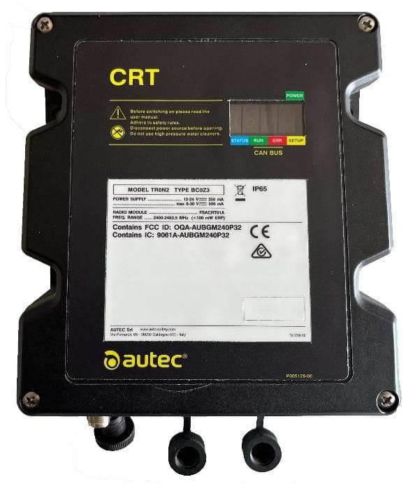
OQA-TR0N2BC0Z3
Jun 09, 2026Transceiver unit
Equipment Class
DSS - Part 15 Spread Spectrum Transmitter
OQA-FSAACT01A
Mar 04, 2026Transceiver Unit
Equipment Class
DSS - Part 15 Spread Spectrum Transmitter
OQA-AX0A02Z0W1
Feb 24, 2026Transceiver Unit
Equipment Class
DSS - Part 15 Spread Spectrum Transmitter