OQCWAF24-250
Winncom Technologies Inc.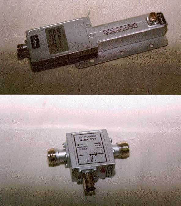
Click to zoom
Application Details
- Equipment Class
- DSS - Part 15 Spread Spectrum Transmitter
- Date of Grant
- Jun 07, 2000
- Application Purpose
- Original Equipment
- Date of Application
- Mar 06, 2000
- Frequency Range
- 2412.00000000 - 2462.00000000
- Company
- Winncom Technologies Inc.
- Country
- United States
Documents & Files
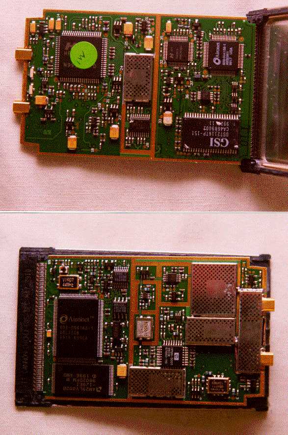
Document Text
Text extracted from the exhibit documents filed with the FCC. Open a document above to read the original.
Users Manual
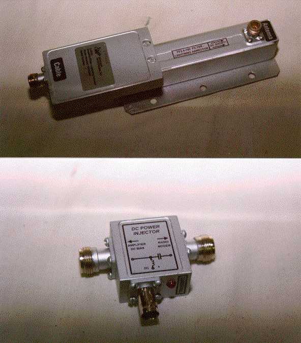
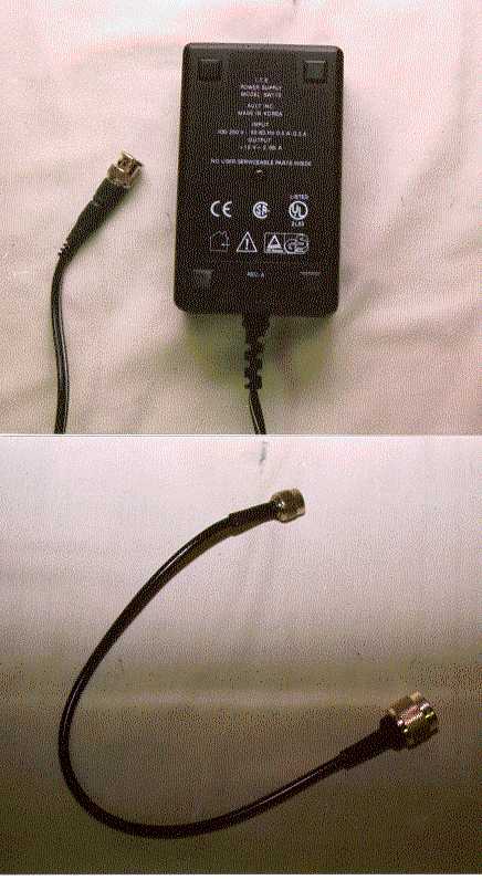
Amp_250_Inst_12_99 Page 1 of 5 RF POWER AMPLIFIER The power amplifier is intended to increase receiver sensitivity and compensate for various line losses (in the feeder, connectors and cable) as well as signal losses due to electromagnetic radiation, in order to attain maximum allowable signal emission. The bi-directional amplifier operates in half-duplex mode in the 2.4 - 2.5 GHz ISM frequency range. The amplifier assembly consists of four main components: 1. Low-noise receive amplifier, transmit amplifier, and switching control unit assembled in a sealed enclosure. 2. Bandpass filter, which determines the usable frequency band of the amplifier and its sensitivity to interference outside of the selected RF band. 3. DC power injector. The DC power injector should be located near a transmitting device, such as a radio modem or a bridge. The power injector connects to the transmitting device and the amplifier assembly via 50 Ohm coaxial cable. 4. 110-220 VAC Power supply. Technical Characteristics Receive Amplifier Gain, dB 25.0 ± 3.0 Noise figure, dB ≤ 3.0 Input saturation power, mW ≅ 10 Transmit Amplifier Automatic gain & power control Input power, mW 0.5 – 100 Max Output power, mW 250.00 Switching power, mW 0.5 ± 0.3 Switching time, mks ≤ 0.5 Bandpass Filter Frequency band (with ripple 0.5 dB ), GHz 2.4 – 2.5 Attenuation in frequency band 2.4–2.5 GHz, (dB) 0.5 Out-of-Band Attenuation @ 2 GHz, (dB) @ 3 GHz, (dB) 60 60 Amp_250_Inst_12_99 Page 2 of 5 DC Power Injector Frequency band (with ripple 0.5 dB ), GHz 2.4 – 2.5 Attenuation in frequency band 2.4–2.5 GHz, (dB) 0.6 RF connector typeN-female Power Supply DC out, V 12 Max output power, W 12 DC Connector typeBNC – male Operating temperature range -50°C — +50°C The filter determines the frequency characteristics of the amplifier. In standard configuration the amplifier is shipped with a 100 MHz filter, main frequency of 2445 MHz, main frequency attenuation of 0.5 dB, and an input shunt for quasi-direct currents. At the foregoing settings signal attenuation is > 60 dB in the 0 - 2.4 GHz and 2.5 - 18 GHz ranges. The amplifier/filter set includes the following: ItemQuantity Amplifier / Filter1 DC Power injector1 Power supply1 Amplifier / filter mounting plate1 U-shaped mast mounting brackets2 Grounding strap1 Amp_250_Inst_12_99 Page 3 of 5 Installation Instructions Important Notice: Read the following installation instructions and all warnings carefully prior to installing the amplifier. Failure to follow installation instructions or tampering with the amplifier or the power supply will void the warranty. 1. Install the amplifier mounting plate, with the amplifier and filter attached, on a mast near the external antenna, using two U-shaped brackets (included). The amplifier can also be installed horizontally on a mounting stand through predrilled holes in the mounting plate. 2.Connect the amplifier to the antenna and DC power injector, as marked, with 50 Ohm coaxial cable. Important: In order for the amplifier to operate properly, and to avoid damage to the amplifier and the power supply, the maximum input power to the amplifier must not exceed 100mW. User must check for proper attenuation. 3. Following installation, a weather sealant of 100% silicone over electrical tape must be applied to all external connectors to protect them from moisture (moisture can cause increased signal losses in the feeder, diminished transmission quality, and possible damage to the connectors and the amplifier). 4. Grounding . Ensure that the mounting mast is properly grounded. Connect the amplifier assembly's grounding strap to the mast with a bolt. Check the ground on the amplifier assembly with an Ω - meter. Warning: Improper grounding can adversely affect amplifier performance and may lead to equipment damage or personal injury. Failure to properly ground the amplifier will void the warranty. The amplifier is not designed to withstand a lightning strike. Amplifier warranty does not apply to damage caused by lightning. Amp_250_Inst_12_99 Page 4 of 5 Operation of the Amplifier • On power up, the amplifier will be in a "receive" mode. The mode switches to "transmit" when the amplifier receives a signal from a radio modem or another transmitting device. A red light on the DC injector indicates that the amplifier is in a "transmit" mode. The red light blinks when the amplifier is connected to a radio bridge, and is half-lit when the amplifier is connected to a radio modem. • A constant red light indicates that the amplifier is continuously in the "transmit" mode and is not communicating properly. This is an abnormal condition that can be caused by any of the following: - High noise level in the feeder of the transmitting device . With time, some radio modems and other transmitting devices develop elevated natural noise levels, even in the "receive" mode. This noise can cause the amplifier to switch from "receive" to "transmit" mode, causing interruptions in communications. This problem can be diagnosed by measuring the natural noise level of the transmitting device with an oscilloscope. If the problem is detected, the transmitting device should be replaced. - External interference . If the amplifier is not properly grounded, external interference can cause the amplifier to intermittently switch to "transmit" mode. This condition has been observed with certain brands of radio modems, due to the modems' poor shielding characteristics. Thus, if the transmitting device is not adequately shielded, several such devices operating in close proximity can interfere with the amplifier's operation. • If the red light does not come on at all, the cable could be defective, or the cable length may exceed maximum allowable length. Important FCC Notice: Operation of RF power amplifiers in the United States is subject to the Federal Communications Commission's regulations in accordance with 47 USC 302. Use of the amplifiers with Part 15 transmitters may be restricted by federal law…
Text truncated - open the document above for the full version.
Users Manual
Amp_250_Inst_12_99 Page 1 of 5 RF POWER AMPLIFIER The power amplifier is intended to increase receiver sensitivity and compensate for various line losses (in the feeder, connectors and cable) as well as signal losses due to electromagnetic radiation, in order to attain maximum allowable signal emission. The bi-directional amplifier operates in half-duplex mode in the 2.4 - 2.5 GHz ISM frequency range. The amplifier assembly consists of four main components: 1. Low-noise receive amplifier, transmit amplifier, and switching control unit assembled in a sealed enclosure. 2. Bandpass filter, which determines the usable frequency band of the amplifier and its sensitivity to interference outside of the selected RF band. 3. DC power injector. The DC power injector should be located near a transmitting device, such as a radio modem or a bridge. The power injector connects to the transmitting device and the amplifier assembly via 50 Ohm coaxial cable. 4. 110-220 VAC Power supply. Technical Characteristics Receive Amplifier Gain, dB 25.0 ± 3.0 Noise figure, dB ≤ 3.0 Input saturation power, mW ≅ 10 Transmit Amplifier Automatic gain & power control Input power, mW 0.5 – 100 Max Output power, mW 250.00 Switching power, mW 0.5 ± 0.3 Switching time, mks ≤ 0.5 Bandpass Filter Frequency band (with ripple 0.5 dB ), GHz 2.4 – 2.5 Attenuation in frequency band 2.4–2.5 GHz, (dB) 0.5 Out-of-Band Attenuation @ 2 GHz, (dB) @ 3 GHz, (dB) 60 60 Amp_250_Inst_12_99 Page 2 of 5 DC Power Injector Frequency band (with ripple 0.5 dB ), GHz 2.4 – 2.5 Attenuation in frequency band 2.4–2.5 GHz, (dB) 0.6 RF connector typeN-female Power Supply DC out, V 12 Max output power, W 12 DC Connector typeBNC – male Operating temperature range -50°C — +50°C The filter determines the frequency characteristics of the amplifier. In standard configuration the amplifier is shipped with a 100 MHz filter, main frequency of 2445 MHz, main frequency attenuation of 0.5 dB, and an input shunt for quasi-direct currents. At the foregoing settings signal attenuation is > 60 dB in the 0 - 2.4 GHz and 2.5 - 18 GHz ranges. The amplifier/filter set includes the following: ItemQuantity Amplifier / Filter1 DC Power injector1 Power supply1 Amplifier / filter mounting plate1 U-shaped mast mounting brackets2 Grounding strap1 Amp_250_Inst_12_99 Page 3 of 5 Installation Instructions Important Notice: Read the following installation instructions and all warnings carefully prior to installing the amplifier. Failure to follow installation instructions or tampering with the amplifier or the power supply will void the warranty. 1. Install the amplifier mounting plate, with the amplifier and filter attached, on a mast near the external antenna, using two U-shaped brackets (included). The amplifier can also be installed horizontally on a mounting stand through predrilled holes in the mounting plate. 2.Connect the amplifier to the antenna and DC power injector, as marked, with 50 Ohm coaxial cable. Important: In order for the amplifier to operate properly, and to avoid damage to the amplifier and the power supply, the maximum input power to the amplifier must not exceed 100mW. User must check for proper attenuation. 3. Following installation, a weather sealant of 100% silicone over electrical tape must be applied to all external connectors to protect them from moisture (moisture can cause increased signal losses in the feeder, diminished transmission quality, and possible damage to the connectors and the amplifier). 4. Grounding . Ensure that the mounting mast is properly grounded. Connect the amplifier assembly's grounding strap to the mast with a bolt. Check the ground on the amplifier assembly with an Ω - meter. Warning: Improper grounding can adversely affect amplifier performance and may lead to equipment damage or personal injury. Failure to properly ground the amplifier will void the warranty. The amplifier is not designed to withstand a lightning strike. Amplifier warranty does not apply to damage caused by lightning. Amp_250_Inst_12_99 Page 4 of 5 Operation of the Amplifier • On power up, the amplifier will be in a "receive" mode. The mode switches to "transmit" when the amplifier receives a signal from a radio modem or another transmitting device. A red light on the DC injector indicates that the amplifier is in a "transmit" mode. The red light blinks when the amplifier is connected to a radio bridge, and is half-lit when the amplifier is connected to a radio modem. • A constant red light indicates that the amplifier is continuously in the "transmit" mode and is not communicating properly. This is an abnormal condition that can be caused by any of the following: - High noise level in the feeder of the transmitting device . With time, some radio modems and other transmitting devices develop elevated natural noise levels, even in the "receive" mode. This noise can cause the amplifier to switch from "receive" to "transmit" mode, causing interruptions in communications. This problem can be diagnosed by measuring the natural noise level of the transmitting device with an oscilloscope. If the problem is detected, the transmitting device should be replaced. - External interference . If the amplifier is not properly grounded, external interference can cause the amplifier to intermittently switch to "transmit" mode. This condition has been observed with certain brands of radio modems, due to the modems' poor shielding characteristics. Thus, if the transmitting device is not adequately shielded, several such devices operating in close proximity can interfere with the amplifier's operation. • If the red light does not come on at all, the cable could be defective, or the cable length may exceed maximum allowable length. Important FCC Notice: Operation of RF power amplifiers in the United States is subject to the Federal Communications Commission's regulations in accordance with 47 USC 302. Use of the amplifiers with Part 15 transmitters may be restricted by federal law…
Text truncated - open the document above for the full version.
Cover Letter(s)
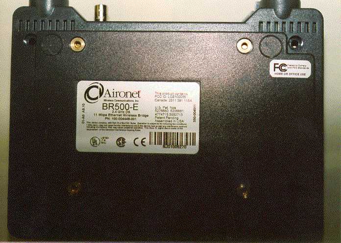
February 16, 2000 Federal Communications Commission 7435 Oakland Mills Road Columbia, MD 21046 ATTN: Applications Examining Division RE: Winncom Technologies, Inc., Certification Application; FCCID: OQCWAF24-250 Gentlemen: Please find the enclosed application for Certification of a Part 15 Direct Sequence Spread Spectrum Transmitter. The Model Aironet BR500-E with AMP250 Bidirectional Amplifier is comprised of the Winncom AMP250 module and the Aironet BR500-E Wireless Bridge, originally FCC Certified under FCCID: LOZ102035. Since the Winncom product is identical with the Aironet BR500-E, no additional Processing Gain tests are needed. The Model Aironet BR500-E with AMP250 Bidirectional Amplifier will interface with a PC via RS-232, and therefore may be considered a Class A Digital Device as well. Class A is justifiable since the system is intended for, and marketed only to commercial operators. The system is priced far over a residential consumer product. Commercial applications are outlined in the User Manual. The amplifier unit incorporates a standard N connector to the antenna, therefore requiring professional installation. The User Manual specifies that only trained certified technicians should install the system. There are many technical steps needed to install an operating half-duplex system, as outlined in the manual. These include antenna support structure, site survey, antenna alignment, test and troubleshoot. All systems sold to businesses are installed under the supervision of Winncom Technologies, Inc. Marketing is limited to sales by authorized dealers. Your consideration is much appreciated. Sincerely, Steven Dayhoff Chief Engineer, NCL
Cover Letter(s)
May 9, 2000 Federal Communications Commission 7435 Oakland Mills Road Columbia, MD 21046 ATTN: Applications Examining Division RE: Winncom Technologies, Inc., Certification Application; FCCID: OQCWAF24-250 Gentlemen: In accordance with FCC Rules Part 0.459, we hereby request confidential treatment for the above referenced Certification application. The items to be held in confidence include the schematic diagrams for the Aironet radio. The Model Aironet BR500-E Wireless Bridge, was originally FCC Certified under FCCID: LOZ102035. The original schematics for this product were filed in confidence by Aironet. In order for us to provide them as part of this application, we agree to file them in confidence to protect Aironet. No changes were made to the BR500-E circuitry by Winncom Technologies, Inc. Your consideration is much appreciated. Sincerely, Steven Dayhoff Chief Engineer, NCL
RF Exposure Info
RF Exposure Calculations: The following information provides the minimum clearance distance for the various antennas provided with the Winncom Technologies AMP250 system, as calculated from FCC OET 65 Appendix B, Table 1B Guidlines for General Population/Uncontrolled Exposure. This calculation is based on the highest EIRP possible from the system, considering maximum power and antenna gain. The formula used was: S = (Po*G)/(4*pi*r^2) Where S = 1.0 mW/cm^2 for 2400 MHz. Where Po = 250 mW max. For: 7 dBi Omni Antenna - Winncom Model WRO2400-70 .... r = 10 cm Antenna Description: 23 inch omni whip For: 12.5 dBi Omni Ant. - Winncom Model WRO2400-125 .. r = 19 cm Antenna Description: For: 13.5 dBi Yagi Ant. - Winncom Model HGY15 . . . . . r = 21 cm Antenna Description: For: 24 dBi Dish Ant. - Winncom Model WRO2400-125 .. .r = 71 cm Antenna Description: Grid Size: 42 inches X 24 inches Dipole Length: 14 inches The following statement will be presented in the AMP250 User Manual: WARNING In order to comply with FCC adopted RF Exposure Requirements, the included antenna must be installed in a manner that will provide clearance from the antenna, to any personnel or member of the public, according to the following guide: WRO2400-70 - 7dBi Omni - 20 cm WRO2400-125 - 12.5 dBi Omni - 20 cm HGY15 - 13.5 dBi Yagi - 21 cm WRO2400-24 - 24 dBi Grid Dish - 71 cm
Test Report
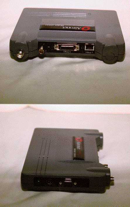
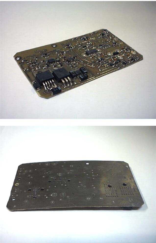
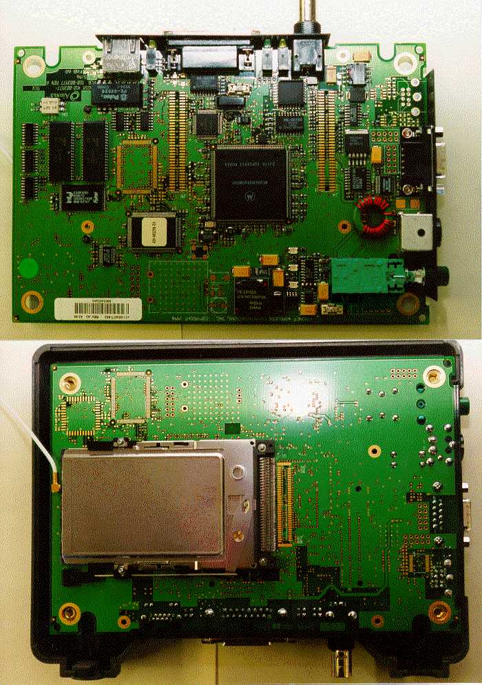
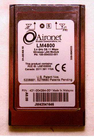
RF Measurement Report Prepared by: NATIONAL CERTIFICATION LABORATORY 8370 Court Avenue, Suite B-1 Ellicott City MD 21043 (410) 461-5548 In Support of: FCC APPLICATION FOR CERTIFICATION for Winncom Technologies, Inc. 30700 Carter Street, Suite A Solon, OH 44139 Model: Aironet BR500-E with AMP250 Amplifier FCC ID: OQCWAF24-250 Demonstration of Compliance with FCC Rules Part 15.247 February, 2000 FCC ID #: OQCWAF24-250 2 TABLE OF CONTENTS Application Form 731 FCC Label Drawing and Location 1.0 Introduction 1.1 Summary 2.0 Description of Equipment Under Test (EUT) 3.0 Test Program 4.0 Test Configuration 5.0 Conducted Emissions Scheme 6.0 Radiated Emissions Scheme TABLES Table 1.EUT Accessories Table 2.Support Equipment Table 3. Measurement Equipment EXHIBITS Exhibit 1.EUT Photographs Exhibit 2. Schematic Diagram Exhibit 3. User Manual NCL PROJ.# WINCOMM-0526B 1.0 Introduction This report has been prepared on behalf of Winncom Technologies, FCC ID #: OQCWAF24-250 3 Inc., to support the attached Application for Certification of a Part 15 Spread Spectrum Transmitter. The Equipment Under Test was the Model Aironet BR500-E with AMP250 Amplifier. Radio-Noise Emissions tests were performed according to FCC Public Notice 54797, titled "Guidance on Measurements for Direct Sequence SST" . The measuring equipment conforms to ANSI C63.2 Specifications for Electromagnetic Noise and Field Strength Instrumentation. Testing was performed at National Certification Laboratory in Ellicott City, MD. Site description and site attenuation data have been placed on file with the FCC's Sampling and Measurements Branch. FCC acceptance was granted on May 26, 1993. 1.1 Summary The Winncom Technologies, Inc. Model Aironet BR500-E with AMP250 Amplifier complies with the FCC limits (15.247) for a Direct Sequence SST. 2.0 Description of Equipment Under Test (EUT) The Aironet BR500-E Wireless Bridge is actually the FCC Certified Model with FCC ID: LOZ102035. Winncom Technologies, Inc. has not modified this product in any manner except for the addition of high gain antennas, and an external amplifier. The EUT Features: Direct Sequence Spread Spectrum Transceiver + 24 dBm RF Output Max. 2412 to 2462 MHz Freq. Range 10 MHz 6 dB Emission Bandwidth 10 Available Channels 5 MHz Channel Separation 11 Mbps Data Rate (Radio Link) Differential DPSK Modulation FCC ID #: OQCWAF24-250 4 3.0 Test Program This report contains measurement charts and data as evidence for the following tests performed: 1. (15.247 b) Peak RF output power. 2. (15.247 d) Power Spectral Density (3kHz Bandwidth). 3. (15.247 c) Field strength of harmonics and spurious out-of-band emissions. 4. (15.247 c) RF Antenna Conducted of harmonics and spurious out-of-band emissions. 5. (15.247 a) 6 dB Emission Bandwidth. 6. (15.207) Power Line Conducted Emissions. 4.0 Test Configuration The BR500-E Wireless Bridge was connected via RS-232 port to a Pentium tower computer for testing. A Win98 Hyperterminal program is used to control the transmitter. The external amplifier is connected in-line between the wireless bridge and antenna via 10 feet of low loss cable. The 10 foot cable is the minimum length supplied with the system. RF power output measurements were taken with an RF power meter at the amplifier output connecter after the 10 ft. cable. RF antenna conducted output tests such as Bandwidth, Spurious/Harmonics, and Power Spectral Density were taken with the amplifier ouput feeding directly into the spectrum analyzer via the 10 ft. cable. The analyzer's internal attenuator was adusted to prevent overloading of the front end. Field strength measurements were taken with the amplifier in-line, and feeding a 7dBi omni, 12.5 dBi Omni, 13.5 dBi Yagi, and 24 dBi Grid Dish antennas. FCC ID #: OQCWAF24-250 5 PEAK POWER TEST RESULTS Limit: 0.250 watts (24 dBm) Condition: Transmitter is set to a single modulated channel. Measurement taken at amplifier antenna connector. Readings from RF Peak Power Meter: BR500-E w/ 250 mW Amp 2412 MHz - +23.7 dBm BR500-E w/ 250 mW Amp 2437 MHz - +24.0 dBm BR500-E w/ 250 mW Amp 2462 MHz - +23.8 dBm FCC ID #: OQCWAF24-250 6 POWER SPECTRAL DENSITY Limit: 8 dBm Resolution Bandwidth: 3 kHz Average Time Interval: 1 second/3 kHz Actual Time Interval used for testing: 1.5 seconds/3 kHz Condition: Transmitter is modulated at 24 dBm RF power. Measurement taken at amplifier antenna connector. Readings from spectrum analyzer: 2412 MHz - -11.2 dBm 2437 MHz - -12.8 dBm FCC ID #: OQCWAF24-250 7 2462 MHz - -14.8 dBm SEE FOLLOWING 3 PLOTS LOW CHANNEL MID CHANNEL FCC ID #: OQCWAF24-250 8 HIGH CHANNEL FCC ID #: OQCWAF24-250 9 6 dB EMISSION BANDWIDTH FCC ID #: OQCWAF24-250 10 Minimum 6 dB BW: 0.5 MHz RBW Setting on S.A.: 100 kHz Condition: Transmitter is set to a single modulated channel. Measurement taken at amplifier antenna connector. Readings from spectrum analyzer: 2412 MHz - 10.4 MHz Occupied BW 2437 MHz - 12.4 MHz Occupied BW 2462 MHz - 10.8 MHz Occupied BW SEE FOLLOWING 3 PLOTS FCC ID #: OQCWAF24-250 11 LOW CHANNEL MID CHANNEL FCC ID #: OQCWAF24-250 12 HIGH CHANNEL FCC ID #: OQCWAF24-250 13 RF ANTENNA CONDUCTED SPURIOUS/HARMONICS EMISSIONS FCC ID #: OQCWAF24-250 14 Limit: 20 dB below Carrier Level Measured with 100 kHz RBW RBW Setting on S.A.: 100 kHz Condition: Transmitter is set to a single modulated channel. RF power = 24 dBm Measurement taken at amplifier antenna connector. Three separate Measurements are performed to show harmonic and spurious emissions generated with the transmitter tuned to low, middle, and high parts of the spectral range. SEE FOLLOWING 3 DATA TABLES FCC ID #: OQCWAF24-250 15 FCC PART 15.247(c) - CONDUCTED SPURIOUS EMISSIONS Frequency of Carrier = 2412 MHz Limit = 20 dBc Condition: Transmitter is set to a single modulated channel. TEST RESULTS LIMIT: -20 dB FROM PEAK CARRIER COMPONENT FREQUENCY (MHZ) RESULT (dB FROM PEAK) HARMONIC 4824.00 - 43.0 HARMONIC 7236.00 - 48.0 HARMONIC 9648.00 - 57.0 HARMONIC 12060.00 - 65.0 HARMONIC 14472.00 …
Text truncated - open the document above for the full version.
Test Report
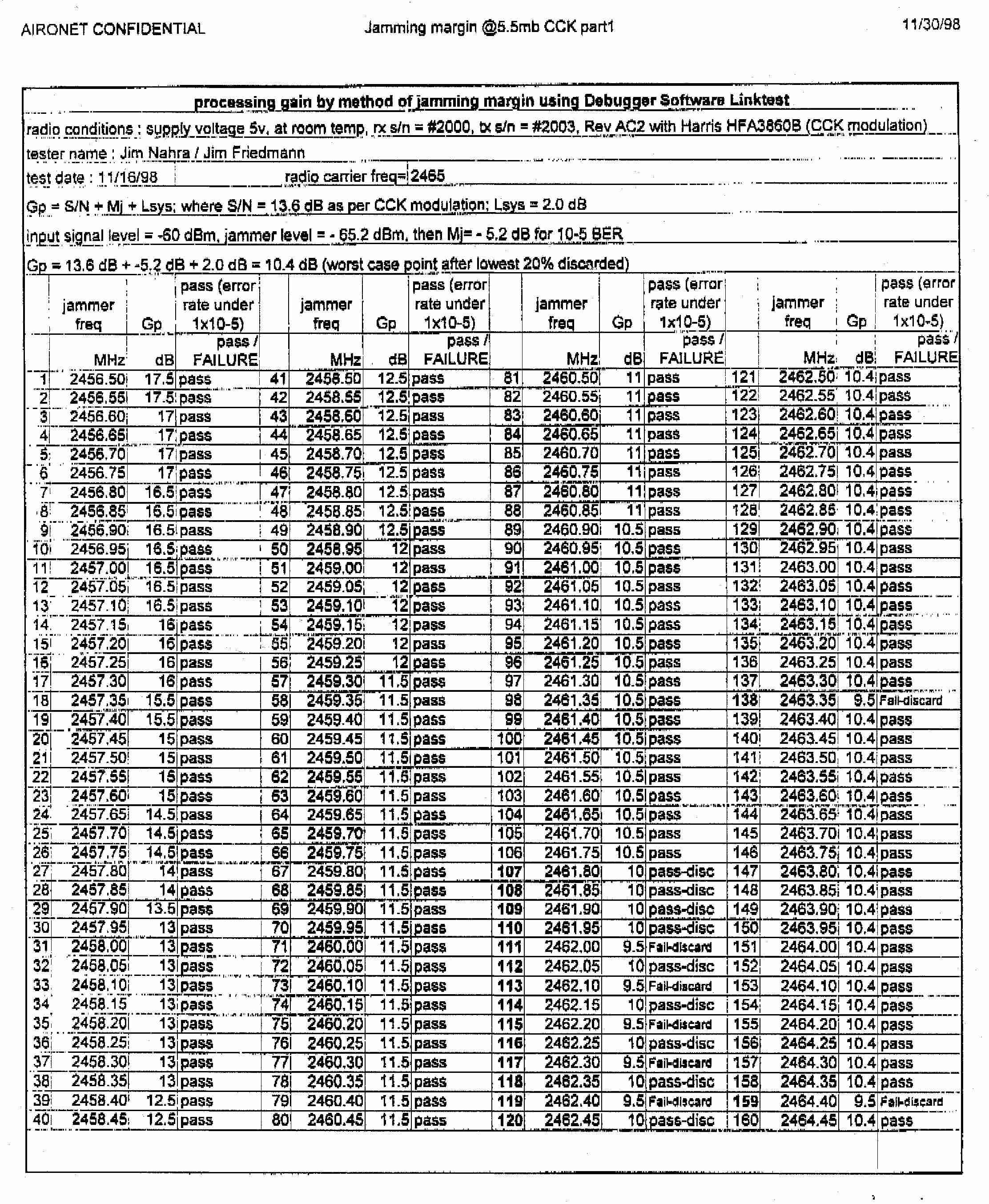
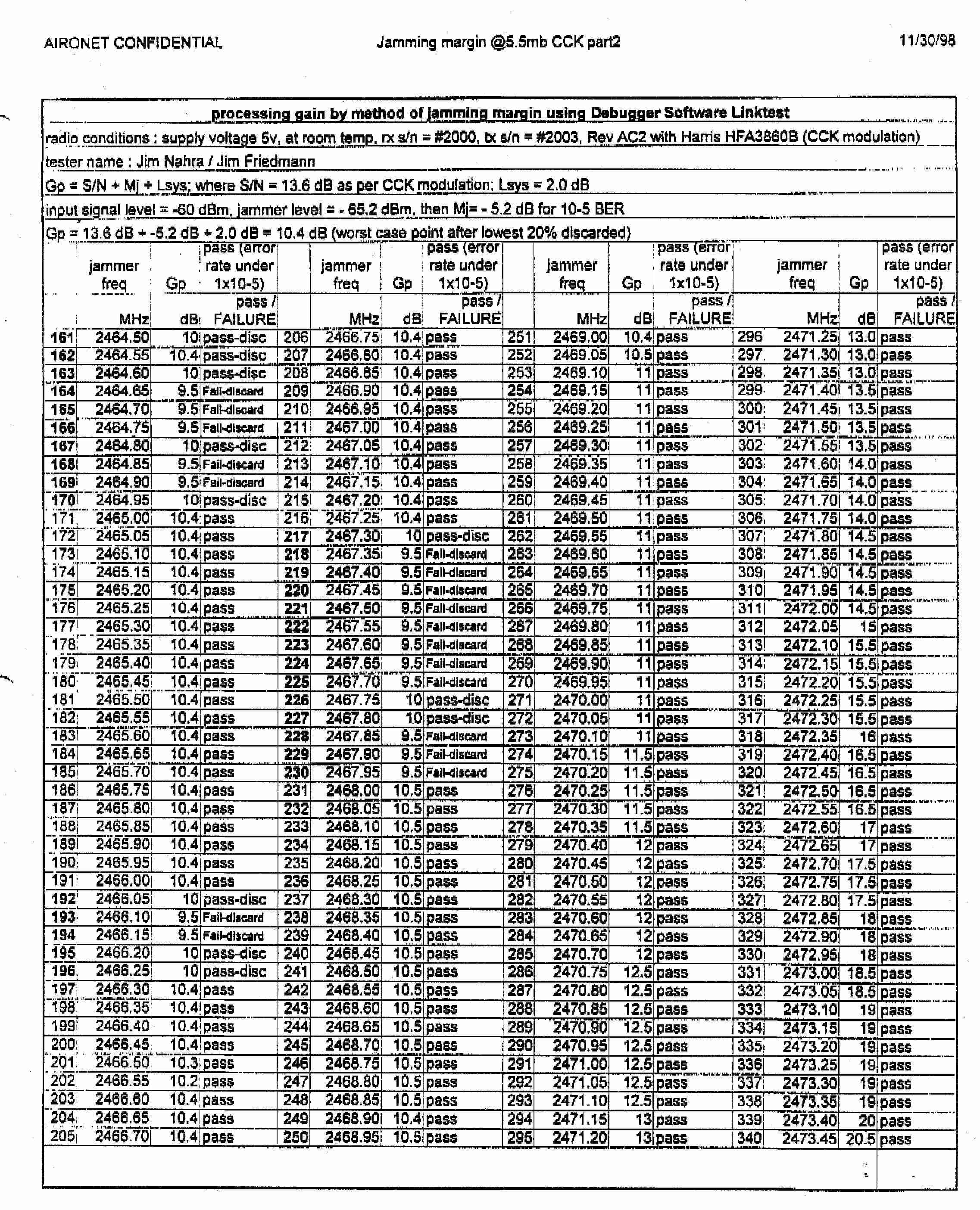
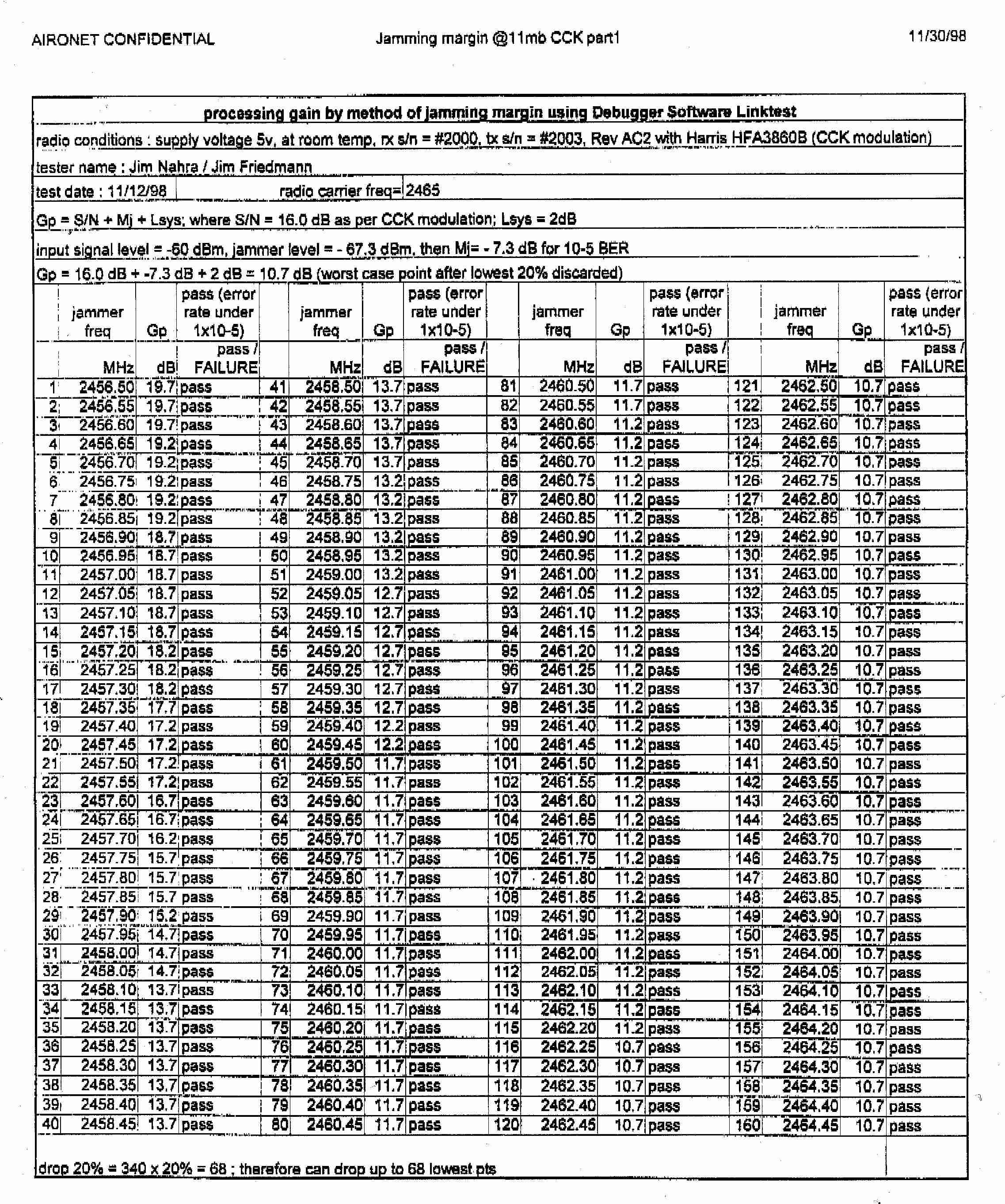
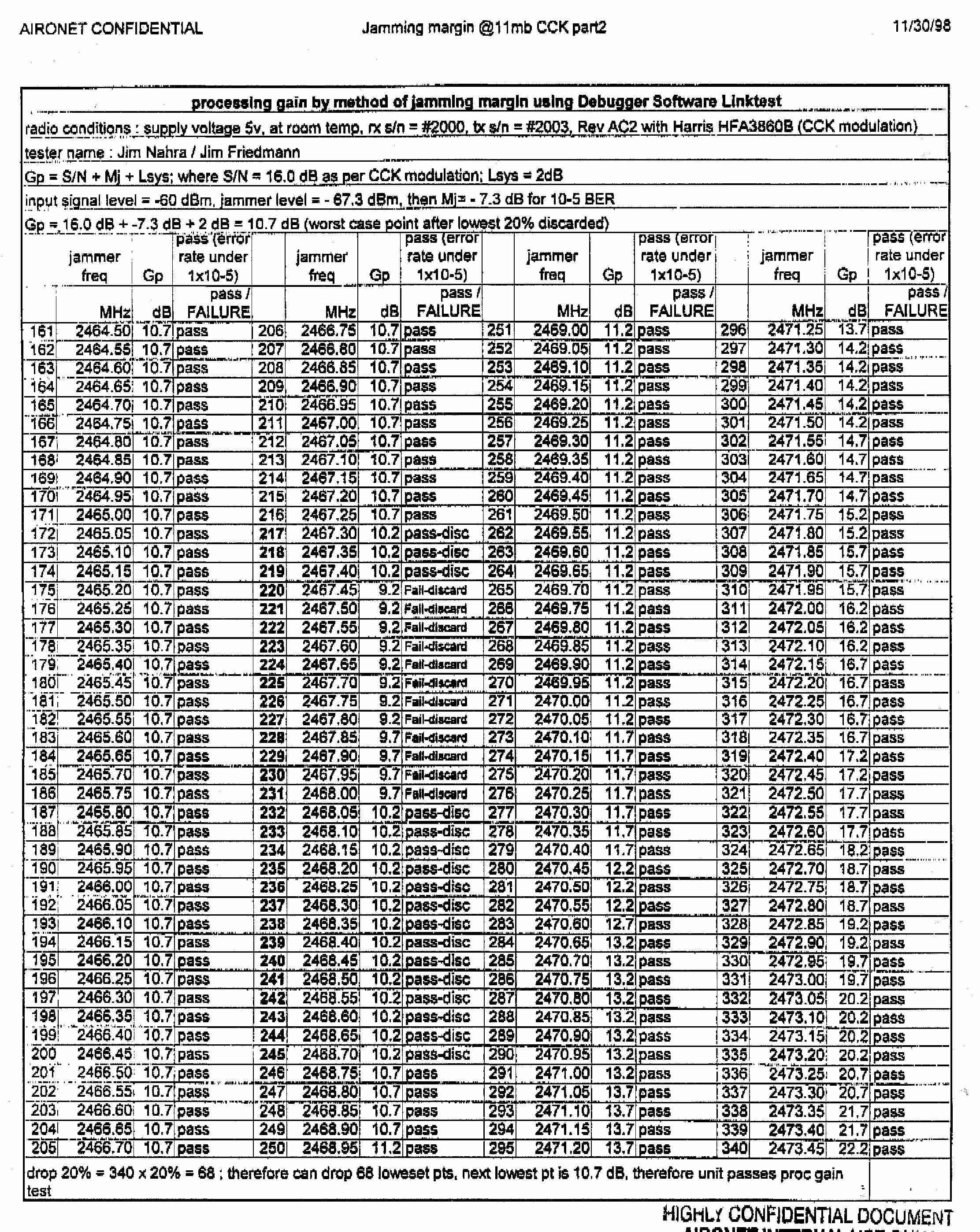
To FCC Review Engi neer: The following data pages represent processing gain tests performed on an Aironet SST unit. Test were performed using 1, 2, 5.5, and 11 mbps data rates. The data is representative of several Aironet products including the BR500-E Wireless Bridge, with FCCID: LOZ102035. Dave Case Aironet
Test Report
FCC 15.209 RADIATED EMISSIONS DATA UPPER BAND EDGE CARRIER : 2462 MHz @ 250 mW ANTENNA: 7 dBi OMNI PEAK PEAK FREQ POL SPEC A AF/CL PREAMP E-FIELD LIMIT MRGN MHz H/V dBuV dB/m GAIN dBuV/m dBuV/m dB 2483.5 H 27.0 34.0 -25 36.0 74.0 -38 AVRG AVRG FREQ POL SPEC A AF/CL PREAMP E-FIELD LIMIT MRGN MHz H/V dBuV dB/m GAIN dBuV/m dBuV/m dB 2483.5 H 8.0 34.0 -25 17.0 54.0 -37 CONDUCTED BAND EDGE OUTPUT FCC 15.209 RADIATED EMISSIONS DATA UPPER BAND EDGE CARRIER : 2462 MHz @ 250 mW ANTENNA: 13.5 dBi YAGI PEAK PEAK FREQ POL SPEC A AF/CL PREAMP E-FIELD LIMIT MRGN MHz H/V dBuV dB/m GAIN dBuV/m dBuV/m dB 2483.5 H 29.0 34.0 -25 38.0 74.0 -36 AVRG AVRG FREQ POL SPEC A AF/CL PREAMP E-FIELD LIMIT MRGN MHz H/V dBuV dB/m GAIN dBuV/m dBuV/m dB 2483.5 H 10.0 34.0 -25 19.0 54.0 -35 FCC 15.209 RADIATED EMISSIONS DATA UPPER BAND EDGE CARRIER : 2462 MHz @ 250 mW ANTENNA: 24.0 dBi GRID DISH PEAK PEAK FREQ POL SPEC A AF/CL PREAMP E-FIELD LIMIT MRGN MHz H/V dBuV dB/m GAIN dBuV/m dBuV/m dB 2483.5 H 28.0 34.0 -25 37.0 74.0 -37 AVRG AVRG FREQ POL SPEC A AF/CL PREAMP E-FIELD LIMIT MRGN MHz H/V dBuV dB/m GAIN dBuV/m dBuV/m dB 2483.5 H 8.0 34.0 -25 17.0 54.0 -37
Test Report
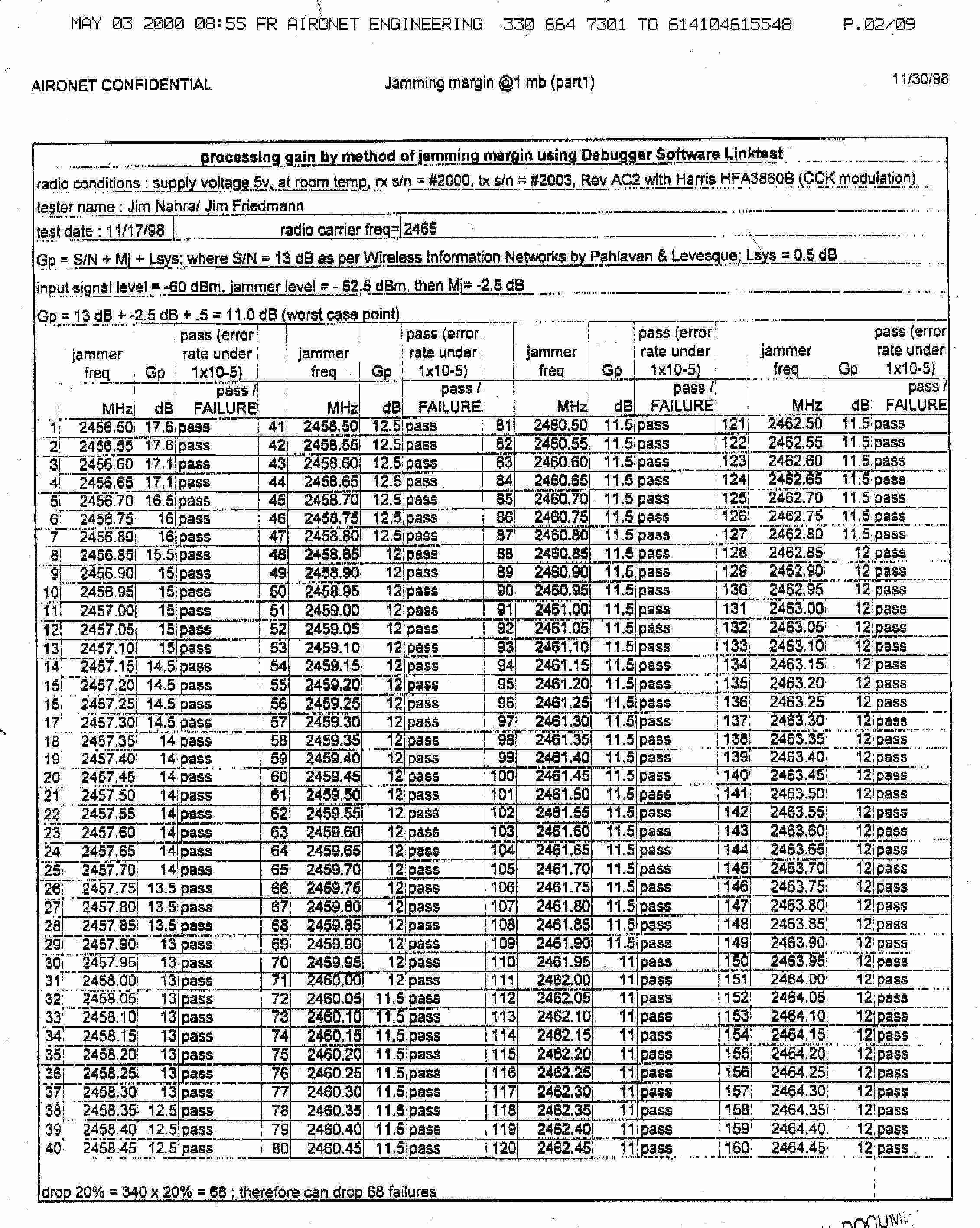
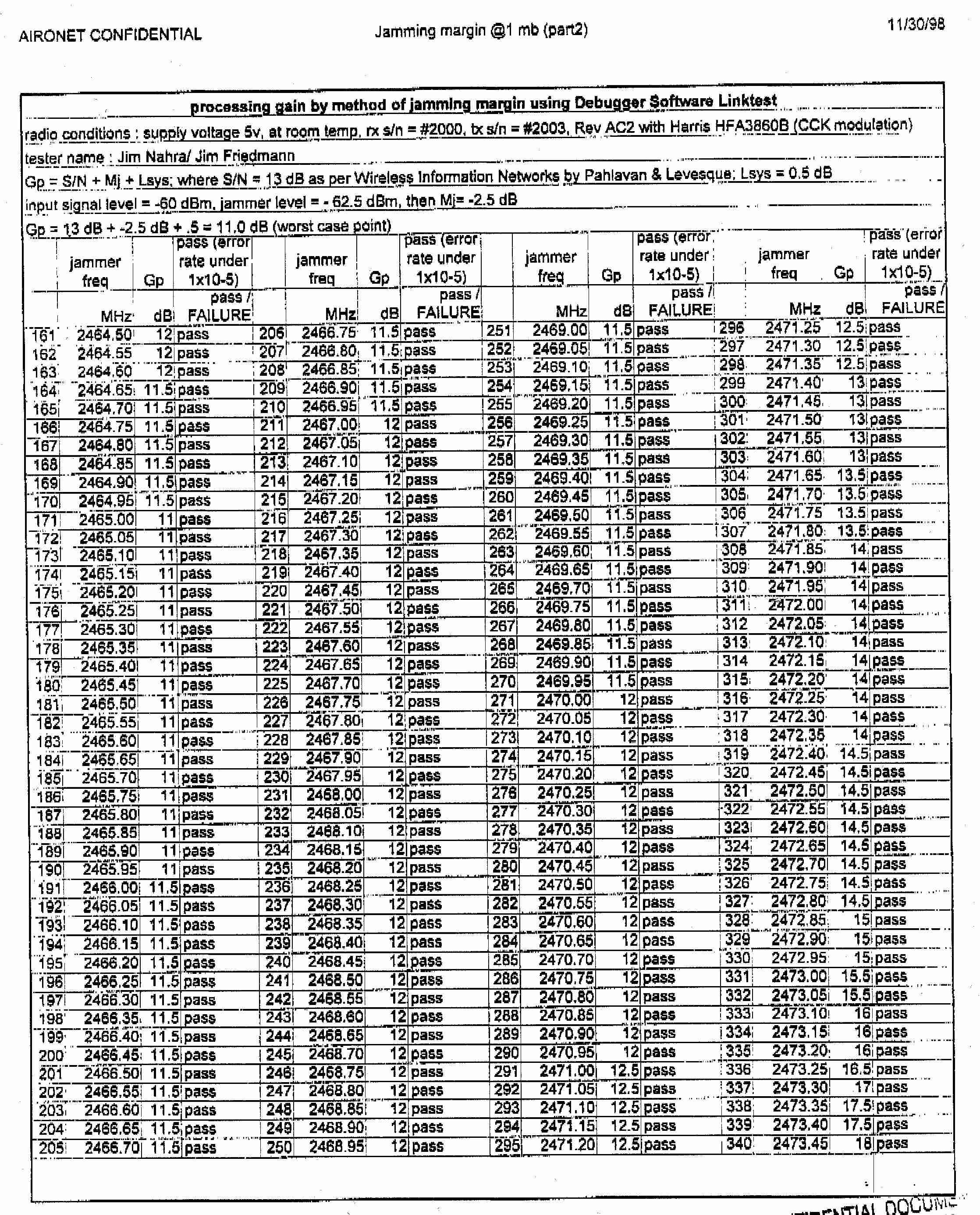
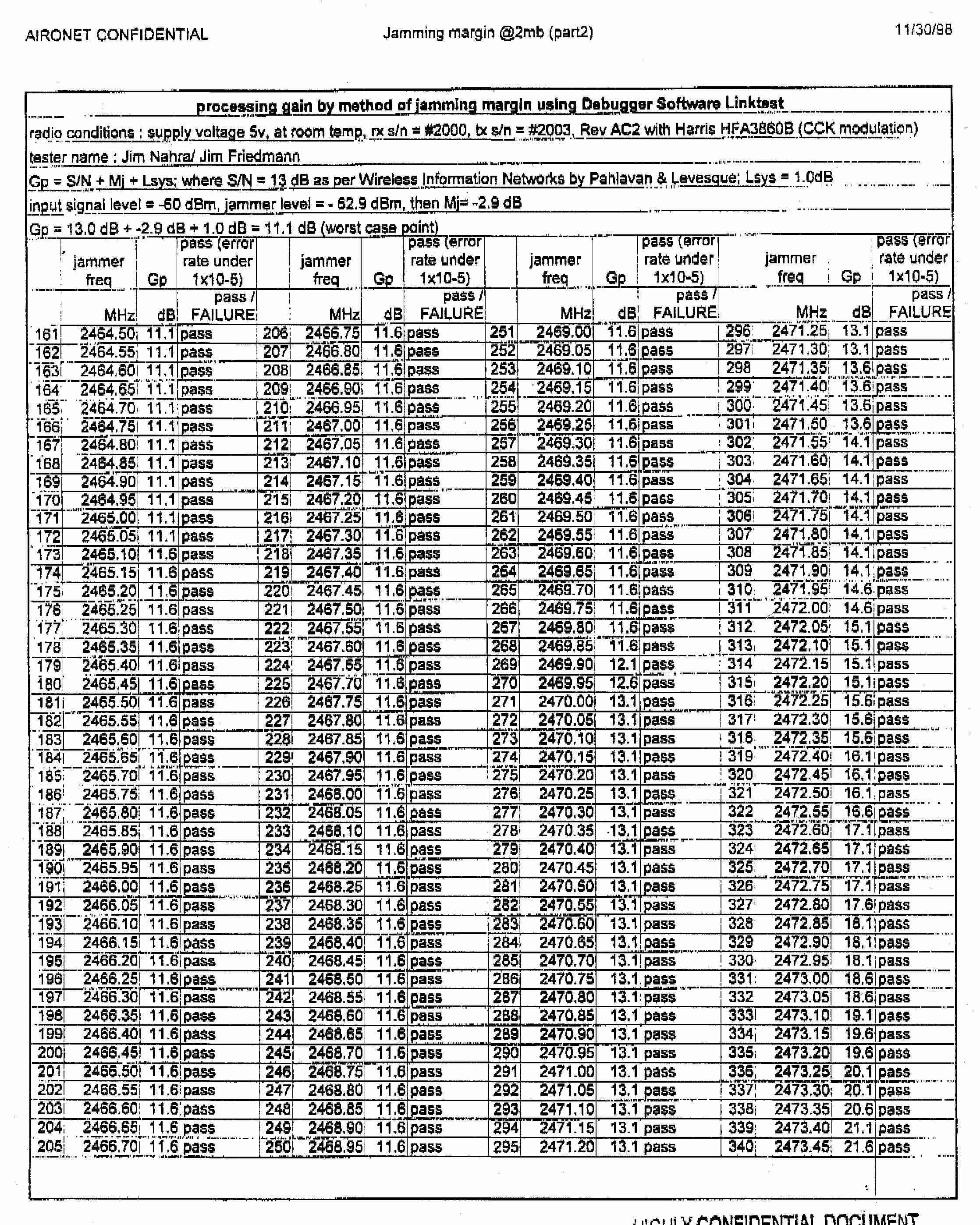
Aironet Confidential 1 05/25/00 Radio Circuit Description The 4800B Spread Spectrum Transceiver operates in the 2.4 Ghz ISM band, using Direct Sequence modulation techniques. The transmit/receive and data packetization operations are under the control of a protocol processor (MAC) internal to the transceiver assembly. Logic Section : A digital ASIC is employed in the logic section of the radio, providing the following functions: 1) Generation of the spreading code, combination of the code with the incoming data stream. 2) Despreading and demodulation of the incoming baseband spread signal. 3) Determination of the transmit/receive sequence. RF Section (refer to 4800B radio block diagram) : The transmitter chain includes a shaping bandpass filter followed by a vector modulator. This signal is further filter by a saw filter at the IF frequency of 374 Mhz. This signal is then mixed up to the 2400-2483.5 Mhz band. A RF filter at the output of the mixer removes any other mixing products. A power amplifier chain brings the signal up to the final output level of 30 mwatts. Through the TX/RX sw itch, the signal is passed through a dielectric bandpass filter to the antenna port. The radio has diversity, so two antenna ports are provided. Transmitter frequency is determined by the 44.0 Mhz reference oscillator, with +/- 25 ppm accuracy. The receiver utilizes the same antenna filtering and TX/RX, followed by a LNA. A mixer circuit brings the signal to the 374 Mhz IF, where a SAW filter shapes the IF spectral envelope. This filter provides the primary rejection against adjacent channel interference. An IF amplifier followed by an IF limiter brings the signal up to the level needed for the I and Q vector demodulator. A buffer amplifier and filter are used to shape the signal for the PHY digital ASIC which despreads and decodes the signal. The 374 Mhz voltage controlled oscillator is controlled by a synthesizer/PLL system comprised of a prescaler and programmable dividers. The 2026-2450 Mhz voltage controlled oscillator is also controlled by a synthesizer/PLL system. Both local oscillators use a reference signal for the PLL which is derived from the 44.0 Mhz master reference oscillator. Aironet Confidential 2 05/25/00 PRODUCT NAME:AIRONET 4800B RADIO NAME OF TEST:The Processing Gain of a Direct Sequence System. FCC Part 15.247 (e) specifies: The processing gain of a direct sequence system shall be at least 10 dB. Guidance on measurement by FCC The processing gain may be measured using the CW jamming margin method. The test consists of stepping a signal generator in 50khz increments across the passband of the system. At each point, the generator level required to the produce the recommended Bit Error Rate (10-5) is recorded. This is the jammer level. The output power of the transmitting unit is measured at the same point. The Jammer to Signal (J/S) ratio is then calculated. Discard the worst 20% of the J/S data points. Total losses in a system including transmitter and receiver, should be assumed to be no more than 2 dB. therefore, processing gain = S/N + Mj + Lsys Where : S/N = Signal to noise ratio required at the receiver output for 10-5 error rate of a ideal receiver for your demodulation scheme Mj = Jammer to signal ratio Lsys = System losses (2dB max) Test results : for 1 mb data rate: S/N = 13 dB ; taken from Wireless Information Networks by Pahlavan & Levesque Mj = - 4.2 dB ; worst case jamming margin from tests in lab Lsys = 2.0 dB ; system losses therefore the processing gain at 1mb is 13 dB - 4.2 dB + 2.0 dB = 10.8 dB for 2 mb data rate: S/N = 13 dB ; taken from Wireless Information Networks by Pahlavan & Levesque Mj = - 4.2 dB ; worst case jamming margin from tests in lab Lsys = 2.0 dB ; system losses therefore the processing gain at 2mb is 13 dB – 4.2 dB + 2.0 dB = 10.8 dB Aironet Confidential 3 05/25/00 for 5.5 mb data rate: S/N = 13.6 dB ; taken from Harris CCK encoding modulation Mj = - 4.4 dB ; worst case jamming margin from tests in lab (after 20% discard) Lsys = 2.0 dB ; system losses therefore the processing gain at 5.5mb is 13.6 dB - 4.4 dB + 2.0 dB = 11.2 dB for 11 mb data rate: S/N = 16.0 dB ; taken from Harris CCK encoding modulation Mj = - 7.4 dB ; worst case jamming margin from tests in lab (after 20% discarded) Lsys = 2.0 dB ; system losses therefore the processing gain at 11mb is 16.0 dB - 7.4 dB + 2.0 dB = 10.6 dB Aironet Confidential 4 05/25/00 AI RONET CONFI DENTIAL RF Systems Engi neering dwg: J. Friedmann Fil e:FCC025_2.ds4 Date: 3/21/96 rev: 2. 4 Ghz SPREAD SPECTRUM RADI O, 2nd GEN Jammer Test, R240 eng: J. Friedmann Transmitter Jamming Test Setup AI RONET Si g GenPower Met er Recei ver Bit Error Rate Tester splitsum Aironet Confidential 5 05/25/00 4800B Spread Spectrum Transceiver Alignment Procedures Set power out: put radio in TX mode, use power meter to set power out. 1)TX on,ch 12-84: set power amp output power by adjusting voltage to the IF attenuator in the tx chain. This is done by software, which changes the DAC voltage output. TX power out; set power to +15dBm + 1dB /-1 dB for highest power setting
Contact Information
Applicant
Michael P. Maly(Executive Vice President)
Technical Contact
National Certification LabSteven Dayhoff
[email protected]410 461 5548
8370 Court Ave. · Ellicott City, Maryland · United States
Non-Technical Contact
National Certification LabSteven Dayhoff
[email protected]410 461 5548
Test Firm
National Certification LaboratoryBrian Haghtalab
Technical Specifications
| # | Rule Parts | Frequency Range | Power Output |
|---|---|---|---|
| 1 | 15C | 2.41 GHz - 2.46 GHz | 250.00 mW |
Other Applications from Winncom Technologies Inc.
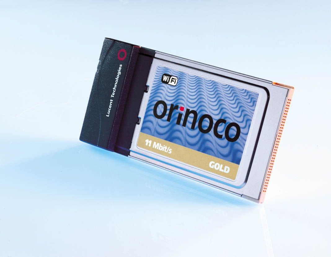
OQCWAF24-1000L
Jun 28, 2001Wireless LAN Card with amplifier
Equipment Class
DSS - Part 15 Spread Spectrum Transmitter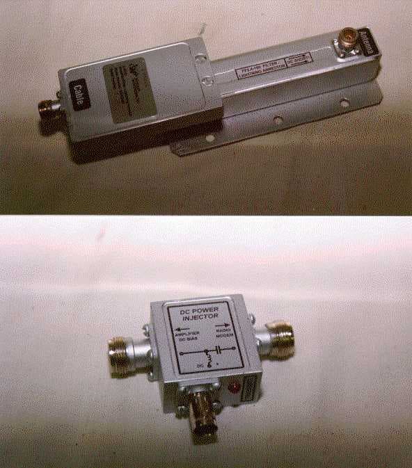
OQCWAF24-1000
Jun 07, 2000DSS - Part 15 Spread Spectrum Transmitter
Equipment Class
DSS - Part 15 Spread Spectrum Transmitter