OQMS5Radio Module 2.4GHz
Jay Electronique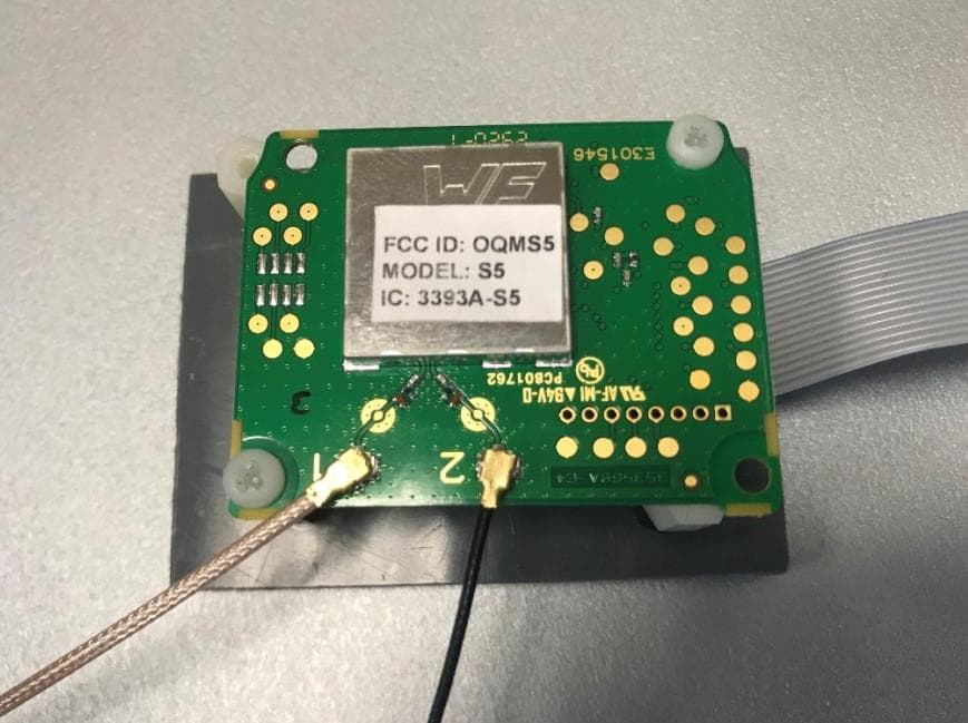
Click to zoom
Application Details
- Equipment Class
- DTS - Digital Transmission System
- Date of Grant
- May 17, 2021
- Application Purpose
- Original Equipment
- Date of Application
- May 03, 2021
- Equipment Note
- Radio Module 2.4GHz
- Frequency Range
- 2402.00000000 - 2480.75000000
- Company
- Jay Electronique
- Country
- France
Documents & Files
Document Text
Text extracted from the exhibit documents filed with the FCC. Open a document above to read the original.
Users Manual
Page 1 / 19 Radio Module 2.4GHz integration manual Document edited by: Conductix Wampfler - Jay Electronique Date: December 10, 2020 Conductix-Wampfler Jay Electronique ZAC La Bâtie | 37, rue Champrond | 38334 Saint-Ismier Cedex France www.conductix.com Page 2 / 19 Table of content Table des matières 1 ABout Manual ..................................................................................... 3 2 Product description ........................................................................... 3 3 Quick Reference Data ........................................................................ 4 4 PIN Description ................................................................................... 5 5 Block Diagram .................................................................................... 6 6 Chip Radio .......................................................................................... 7 7 FCC statement .................................................................................... 8 8 IC Statement ....................................................................................... 9 9 Authorized ANTENNAs .................................................................... 10 9.1 Pulse ........................................................................................................................................... 11 9.2 Inventek System ......................................................................................................................... 12 9.3 Yageo .......................................................................................................................................... 14 9.4 EBDS ........................................................................................................................................... 15 9.5 Siretta .......................................................................................................................................... 17 9.6 RF Solution ................................................................................................................................. 18 10 Revision History ............................................................................ 19 Page 3 / 19 1 ABOUT MANUAL This module installation manual is only intended for the module integration in products manufacture of Jay electronique. All recommendations described in this document about this module also extends to the host product instruction manual. Only persons who are ability and who have training deliver by jay electronique are authorized to change this module in the products. 2 PRODUCT DESCRIPTION This radio transceiver provides range communication in the band 2.4GHz. The radio module is completely shielded and certified for operation under the US radio regulations for license- free use. Features • 2.4GHz transceiver • High sensitivity • High efficiency PA • Low energy consumption • DSSS & FSK & GFSK supported modulations • Excellent blocking immunity • Easy to use data interface • Conform with FCC CFR 47 part 15 Applications Remote controlled machines Cranes Page 4 / 19 3 QUICK REFERENCE DATA Parameter Module Frequency band 2400 – 2483.5 MHz Number of channels 64 Channel bandwidth 1.25 MHz Data rate 44.4 Kb/s Max output power (typ.) + 10 dBm Sensitivity -120 dBm Supply voltage 3.3 to 4.2 Vdc Current consumption, RX 10 mA Current consumption, TX 15 to 45 mA Page 5 / 19 4 PIN DESCRIPTION Pin no Pin name Description 1 EN_PA PA / Switch Rx – Tx 2 PWRF2 Not used 3 RTS_TXEN_RADIO Not used 4 CTS/RXTX/RXEN_RADIO Not used 5 VAccu Supply voltage input 6 GND System ground 7 SPI_uc_SCK/ON_OFF SPI Clock 8 SPI_uc_MISO SPI MISO 9 SPI_uc_MOSI SPI MOSI 10 RESET_RADIO Reset 11 SEL_FILLE Download microcontroller firmware 12 SPI_uc_NSS/CONFIG_RADIO SPI Chip Select 13 RSSI_RADIO Not used 14 DATA_RX UART RX Data 15 DATA_TX UART TX Data 16 GND System ground Page 6 / 19 5 BLOCK DIAGRAM Page 7 / 19 6 CHIP RADIO The chip radio used is the SX1280 of SEMTECH company. The SX1280 are half-duplex transceivers capable of low power operation in the worldwide 2.4 GHz ISM band. The radio features a high efficiency transmitter and a high linearity receive chain that are both accessed via a common antenna port pin. Frequency conversion between RF and baseband (low-IF) is governed by a digital PLL that is referenced to a 52 MHz crystal. Both transmit and receive chains are interfaced by data converters to the ensuing digital. The analog front end features a single antenna port connection to an integrated matching circuit that permits half- duplex operation of the radio without external RF switching. Transceiver Block Diagram: The modem uses spread spectrum modulation and Forward Error Correction (FEC) techniques to increase the range and robustness of radio communication links. In this modulation the spreading of the spectrum is achieved by generating a chirp signal that continuously varies in frequency. An advantage of this method is that timing and frequency offsets between transmitter and receiver are equivalent, greatly reducing the complexity of the receiver design. The frequency bandwidth of this chirp is equivalent to the spectral bandwidth of the signal. The wanted data signal is chipped at a higher data rate and modulated onto the chirp signal. The relationship between the wanted data bit rate, symbol rate and chip rate for the modulation can be expressed as follows: We can define the modulation bit rate, Rb, as: Rb = SF * 1 / [2 SF /BW] bits/sec Where: Rb = Raw Data Rates SF = spreading factor (7..12) BW = modulation bandwidth (Hz) Below principal parameters configured in the radio chip SX1280: - Type of modulation: spread spectrum modulation - Raw Data Rates: 44 kb/s (SF7) - Bandwidth: 812 kHz Page 8 / 19 7 FCC STATEMENT The OEM integrators are responsible for ensuring that the end-user has no manual instructions to remove or install module. These following instructions/statements shall be reported on the User Man…
Text truncated - open the document above for the full version.
Cover Letter(s)
CONFIDENTIALITY REQUEST Bureau Veritas Consumer Product Services Inc. One Distribution Center Circle #1 Littleton, MA 01460 USA April 19, 2021 Re: Confidentiality request FCC ID: OQMS5 Gentlemen, Jay electronique requests, pursuant to 47CFR 0.457(d) and 0.459, post grant confidentiality for portions of the material contained in this application. The following document regarding this submission for FCC ID: OQMS5 shall be kept confidential: LONG-TERM CONFIDENTIALITY: 1.Schematic Diagram of the equipment 2.Block Diagram description of the equipment 3.Operational description of the equipment (fil e: Schematic - OQMS5.pdf) (fil e: Block Diagram - OQMS5.pdf) (file: Operational Description - OQMS5.pdf) Specifically, these exhibits contain information relating to circuit function and complexity that could be of benefit to competitors. The material contains trade secrets and confidential information that Jay electronique does not customarily release to the public and which is otherwise not generally available to the public. Rega rds, Respo nsible party: Patrick BERTHET Title: General Manager Signature:
Cover Letter(s)
Letter of Agency March 25, 2021 To: Federal Communications Commission 7435 Oakland Mills Road Columbia, MD 21046-1609 Curtis-Straus LLC TCB One Distribution Center Circle #1 Littleton, MA 01460 We, the undersigned Jay electronique hereby authorize Anthony MERLIN, LCIE SUD EST, to act on our behalf in all matters relating to all processes required for FCC certification of our devices. Any and all acts carried out by the above agent on our behalf shall have the same effects as acts of our own. This authorization is valid until: June 1st, 2021 If you have any questions regarding this authorization, let us know please. Sincerely, Patrick BERTHET Signature
Cover Letter(s)
Document edited by: Conductix Wampfler - Jay Electronique Date: April 21, 2021 Page 1 / 2 JAY electronique Conductix-Wampfler ZAC La Bâtie | 37, rue Champrond | 38334 Saint-Ismier Cedex France www.conductix.com Date: April 21, 2021 FCC ID: OQMS5 We declare that the requirement of KDB 353028 D01 antennas Part 15 transmitters V01 section II.A.2.c have been met for our safety radio remote controls products, GAMA, BETA, PIKA, MOKA, ALTO, ELIO, TIMO, & NEMO. KDB 353028 D01, section II.A.2.c Professional installation: i) Professional installation must be justified in the filing, and grant condition must state “This device must be professionally installed. Justification to support professional installation is given by the fact that our products are safety radio control system and is considered as a machine control device and a safety component used to stop machine as specified by the Machine Directive 2006/42/EC. ii) Professional installation does not permit use of any antenna with the transmitter; the permitted types of antenna must be specified. Only antennas specified within the installation and user manual (doc: 351260; § 7.3.2.4) submitted with this filling are permitted with the transmitter. iii) The applicant should address the following items when justifying professional installation. (1) To qualify for professional installation, the applicant must explain why the hardware is not readily available to average consumer. Due to safety function of our products and these will not be sold directly to the general public through retail store, therefore the hardware is not readily available to average consumer. (2) Marketing—Device cannot be sold via retail to the general public or by mail order; it must be sold to authorized dealers or installers only. Our products will not be sold directly to the general public through retail store. it will be sold to authorized dealers or installers only. (3) Filing must show that intended use is not for consumers and general public; rather device is generally for industrial/commercial use. The wireless module is intended use only in JAY safety remote control products. Document edited by: Conductix Wampfler - Jay Electronique Date: April 21, 2021 Page 2 / 2 (4) Explain what is unique, sophisticated, complex, or specialized about the equipment that REQUIRES it to be installed by a professional installer? The professional installers need to know how to install, to configure and set the correct parameters in order to ensure safe use. And as is mentioned, the installer before commissioning must following the instructions of paragraph §7 and §9 in installation and user manual (doc: 351260). iv) Other professional installation requirements. (1) Installation must be controlled. The products are intended for use in industrial solutions and requires careful consideration about safety function control on the reliability of the devices and on the national and local safety requirements following EEC Machine directive. (2) Installed by licensed professionals (e.g., device sold to dealer who hire installers). Our products are sold by providers of industrial solutions who employ trained staff for the installation of safety solutions. (3) Installation requires special training (e.g., special programming, access to keypad, field strength measurements made). The installation of the products requires consideration of the environment and position of the installation for ensure that the communication field strength do in best condition, following paragraph §7.3 of the installation and user manual (doc 351260). Sincerely yours, Responsible Party: Name: PATRICK BERTHET Position: SITE DIRECTOR Address: ZAC la Bâtie – Rur Champrond 38330 Saint Ismier France Mail: [email protected] Date: Signed by: BERTHET P. Applicant: Signature
Cover Letter(s)
May 17, 2021 LIMITED MODULAR APPROVAL Attestation letter Bureau Veritas Consumer Products Services Inc. One Distribution Center Circle #1 Littleton, MA 01460 USA Re: Limited Modular Approval attestation letter FCC ID: OQMS5 IC: 3393A-S5 Gentlemen, The S5 meets the requirements for limited modular approval as detailed in FCC Public notice 15.212 and IC RSS requirements. Limited modular approval is sought as the modules will be installed in only Jay electronique products under our control and under Professional installation requirements. All the host products will be closed products where it will be impossible to access the modular and the antenna connections, only be accessed by disassembly of the transmitter, where such disassembly is not normally required. Compliance to each of the requirements is described below. Clauses Manufacturer’s arguments Modular Approval 15.212 (a)(1)(i) Shielding Shielding provided, S5 is compliant with all FCC part15C and RSS requirements. See Test Report document. 15.212 (a)(1)(ii) Buffered Data/Modulation Chip is compliant with this rule. 15.212 (a)(1)(iii) Power supply regulation Chip is compliant with this rule 15.212 (a)(1)(iv) Antenna The S5 was tested with each type antenna, in worst case configuration of antenna available, one dipole + one monopole, see “test report”. Antenna connectors aren’t considered unique; a Professional installation is provided about this filing; see user manual and justification letter about this. 15.212 (a)(1)(v) Stand-alone configuration The S5 was tested in a stand-alone configuration, see “Test setup photos” document. 15.212 (a)(1)(vi) Label See “Label” document and exhibition label sample 15.212 (a)(1)(vii) Operating The S5 is compliant with all applicable FCC and IC rules. Details for maintaining compliance are given in the “User Manual”. 15.212 (a)(1)(viii) RF Exposure The S5 is compliant with all applicable RF exposure requirements. See “RF exposure” document. Please contact me if you have any further question. Best regards, Patrick BERTHET
External Photos
LCIE SUD EST Laboratoire de Moirans Z.I. Centr’Alp 170, Rue de Chatagnon 38430 MOIRANS – France Page 1/2 INTERNAL PHOTOS OF EQUIPMENT FCCID: OQMS5
ID Label/Location Info
LCIE SUD EST Laboratoire de Moirans Z.I. Centr’Alp 170, Rue de Chatagnon 38430 MOIRANS - FRANCE Page 1/1 PRODUCT LABELING FCCID: OQMS5
Internal Photos
LCIE SUD EST Laboratoire de Moirans Z.I. Centr’Alp 170, Rue de Chatagnon 38430 MOIRANS – France Page 2/2
RF Exposure Info
LCIE SUD EST Laboratoire de Moirans Z.I. Centr’Alp 170, Rue de Chatagnon 38430 MOIRANS – FRANCE RF Exposure Considerations for FCC ID: OQMS5 Per FCC KDB 447498 D01 General RF Exposure Guidance v06 The 1-g and 10-g SAR test exclusion thresholds for 100 MHz to 6 GHz are based on source-based time-averaged maximum conducted output power of the RF channel requiring evaluation, adjusted for tune-up tolerance, and the minimum test separation distance required for the exposure conditions. The minimum test separation distance defined in 4.1 f) is determined by the smallest distance from the antenna and radiating structures or outer surface of the device, according to the host form factor, exposure conditions and platform requirements, to any part of the body or extremity of a user or bystander. Minimum test separation distance: 5 mm Step a) For 100 MHz to 6 GHz and test separation distances ≤ 50 mm The 1-g and 10-g SAR test exclusion thresholds are determined by the following: (max푝표푤푒푟표푓 푐ℎ푎푛푛푒푙 ( 푚푊 ) ) (min푡푒푠푡푠푒푝푎푟푎푡푖표푛 푑푖푠푡푎푛푐푒 ( 푚푚 ) ) × √ 푓 ( 퐺퐻푧 ) ≤3.0 푓표푟 1−푔 푆퐴푅 표푟 ≤7.5 푓표푟 10−푔 푒푥푡푟푒푚푖푡푦 푆퐴푅 Where: f(GHz) is the RF channel transmit frequency in GHz Power and distance are rounded to the nearest mW and mm before calculation31 The result is rounded to one decimal place for comparison The values 3.0 and 7.5 are referred to as numeric thresholds in step b) below The test exclusions are applicable only when the minimum test separation distance is ≤ 50 mm, and for transmission frequencies between 100 MHz and 6 GHz. When the minimum test separation distance is < 5 mm, a distance of 5 mm is applied to determine SAR test exclusion. (dBm) (mW) Min 2.402 -8.3 0.15 5 0.05 3 7.5 Exempt from SAR Mid 2.441 -10.75 0.08 5 0.03 3 7.5 Exempt from SAR Max 2.481 -8.81 0.13 5 0.04 3 7.5 Exempt from SAR Limit for 10-g extremity SAR Verdict Maximum source-based time averaged conducted output power or EIRP (worst case) including tune-up tolerance Channel Frequency (GHz) Minimum separation distance (mm) Result of Eq. 1 Limit for 1-g SAR Conclusion: Therefore our device complies with FCC’s RF radiation exposure limits for general population without SAR evaluation.
Test Report
Bluetooth Low Energy Template: Release February 6, 2020 This document shall not be reproduced, except in full, without the written approval of the LCIE. This document contains results related only to the items tested. It does not imply the conformity of the whole production to the items tested. . Unless otherwise specified or rule defined by the test method, the decision of conformity doesn’t take into account the uncertainty of measures.This document doesn’t anticipate any certification decision. TEST REPORT N°: 169250-755846-A (FILE#1034406) Version : 03 Subject Radio spectrum matters tests according to standards: 47 CFR Part 15.247 & RSS-247 Issue 2 & RSS-Gen Issue 5 Issued to JAY ELECTRONIQUE ZAC La Batie, Rue Champrond B.P.5 38334 – Saint-Ismier cedex FRANCE Apparatus under test Product Radio Module 2.4GHz Trade mark JAY ELECTRONIQUE Manufacturer JAY ELECTRONIQUE Model under test S5 Serial number None FCC ID OQMS5 IC 3393A-S5 Conclusion See Test Program chapter Test date October 21, 2020 to October 22, 2020 and April 29, 2021 Test location Moirans Test Site 6500A-1 & 6500A-3 Sample receipt date October 21, 2020 Composition of document 60 pages Document issued on April 30, 2021 Written by : Approved by : Majid MOURZAGH Anthony MERLIN Tests operator Technical manager TEST REPORT N° 169250-755846-A (FILE#1034406) Version : 03 Page 2/60 PUBLICATION HISTORY Version Date Author Modification 01 October 27, 2020 Majid MOURZAGH Creation of the document 02 December 18, 2020 Majid MOURZAGH Add informations 03 April 30, 2021 Majid MOURZAGH Adding conducted emission tests on power line. Each new edition of this test report replaces and cancels the previous edition. The control of the old editions of report is under responsibility of client. TEST REPORT N° 169250-755846-A (FILE#1034406) Version : 03 Page 3/60 SUMMARY 1. TEST PROGRAM ............................................................................................................................... 4 2. EQUIPMENT UNDER TEST: CONFIGURATION (DECLARED BY PROVIDER) ................................ 5 3. OCCUPIED BANDWIDTH ................................................................................................................. 11 4. 6DB EMISSION BANDWIDTH .......................................................................................................... 14 5. MAXIMUM CONDUCTED OUTPUT POWER ................................................................................... 17 6. POWER SPECTRAL DENSITY ........................................................................................................ 20 7. UNWANTED EMISSIONS INTO NON-RESTRICTED FREQUENCY BANDS AT THE BAND EDGE 23 8. UNWANTED EMISSIONS INTO NON-RESTRICTED FREQUENCY BANDS ................................... 26 9. UNWANTED EMISSIONS IN RESTRICTED FREQUENCY BANDS ................................................ 29 10. POWER LINE CONDUCTED EMISSIONS ....................................................................................... 44 11. UNCERTAINTIES CHART ................................................................................................................ 60 TEST REPORT N° 169250-755846-A (FILE#1034406) Version : 03 Page 4/60 1. TEST PROGRAM References 47 CFR Part 15.247 RSS 247 Issue 2 RSS Gen Issue 5 KDB 558074 D01 DTS Meas Guidance v05r02 ANSI C63.10-2013 Radio requirement: Clause (47CFR Part 15.247 & RSS-247 Issue 2 & RSS-Gen Issue 5) Test Description Test result - Comments Occupied Bandwidth PASS FAIL NA NP(1) 6dB Bandwidth PASS FAIL NA() NP(1) Duty Cycle PASS FAIL NA NP(1) Maximum Conducted Output Power PASS FAIL NA NP(1) Power Spectral Density PASS FAIL NA NP(1) Conducted Spurious Emission at the Band Edge PASS FAIL NA() NP(1) Unwanted Emissions into Non-Restricted Frequency Bands PASS FAIL NA() NP(1) Power Line Conducted Emission PASS FAIL NA(2) NP(1) Unwanted Emissions into Restricted Frequency Bands PASS FAIL NA NP(1) Receiver Radiated emissions PASS FAIL NA NP(1) This table is a summary of test report, see conclusion of each clause of this test report for detail. (1): Limited program (2): EUT not directly or indirectly connected to the AC Power Public Network PASS: EUT complies with standard’s requirement FAIL: EUT does not comply with standard’s requirement NA: Not Applicable NP: Test Not Performed TEST REPORT N° 169250-755846-A (FILE#1034406) Version : 03 Page 5/60 2. EQUIPMENT UNDER TEST: CONFIGURATION (DECLARED BY PROVIDER) 2.1. HARDWARE IDENTIFICATION (EUT AND AUXILIARIES): Equipment under test (EUT): JAY ELECTRONIQUE S5 Serial Number: None Equipment Under Test Power supply: During all the tests, EUT is supplied by V nom : 3.7VDC For measurement with different voltage, it will be presented in test method. Name Type Rating Reference / Sn Comments Supply1 AC DC Battery 3.7Vdc / Powered throught Beta Operator module Voltage table used (for Power Line Conducted Emissions): Type Measurement performed: AC 120VAC/60Hz 240VAC/50Hz DC +12VDC -3.7VDC Battery +3.6VDC -....VDC USB (Laptop auxiliary) 120VAC/60Hz (Laptop auxiliary) 240VAC/50Hz(Laptop auxiliary) TEST REPORT N° 169250-755846-A (FILE#1034406) Version : 03 Page 6/60 Inputs/outputs - Cable: Access Type Length used (m) Declared <3m Shielded Under test Comments 1 Flat cable 16 wires 0.6 Auxiliary equipment used during test: Type Reference Sn Comments JAY BETA operator Module 1 160688001E1 : Equipment information: Frequency band: [2400 – 2483.5] MHz Spectrum Modulation: DSSS (Tested like it) Number of Channel: 64 Spacing channel: 1.25MHz Antenna Type: Integral External Dedicated Antenna connector: Yes No Temporary for test Transmit chains: 1 Single antenna Gain: 5.5dBi worst case (several ref) Antenna requirements §15.203 The transmitter uses two UFL connectors antenna. Therefore, the transmitter meets the requirements of 15.203. Typ…
Text truncated - open the document above for the full version.
Test Setup Photos
LCIE SUD EST Laboratoire de Moirans Z.I. Centr’Alp 170, Rue de Chatagnon 38430 MOIRANS - FRANCE Page 1/1 CONDUCTED AND RADIATED MEASUREMENT PHOTO FCCID: OQMS5 1.1 Conducted emissions 1.2 Radiated emissions With worst dipole and worst monopole antenna
Contact Information
Applicant
Patrick Berthet(Chairman)
Test Firm
LCIE Etablissement Sud-EstAnthony Merlin
Technical Specifications
| # | Rule Parts | Frequency Range | Power Output |
|---|---|---|---|
| 1 | 15C | 2.40 GHz - 2.48 GHz | 41.70 µW |
Other Applications from Jay Electronique
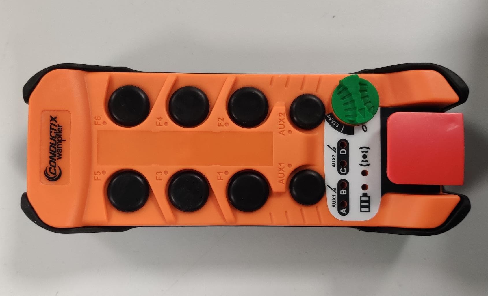
OQMKT
May 02, 2023Industrial Remote Controls
Equipment Class
DSC - Part 15 Security/Remote Control Transmitter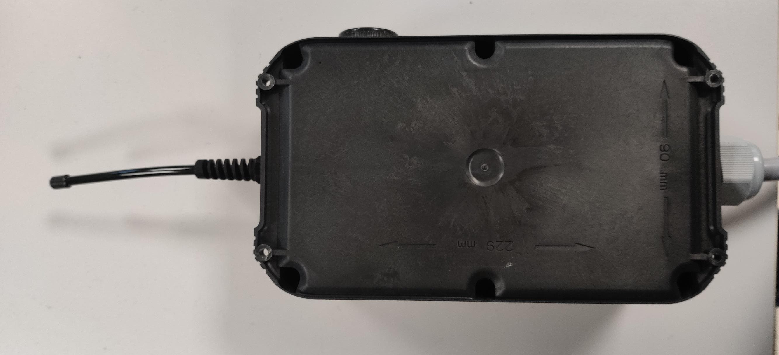
OQMKR
May 02, 2023Industrial Remote Controls
Equipment Class
DSC - Part 15 Security/Remote Control Transmitter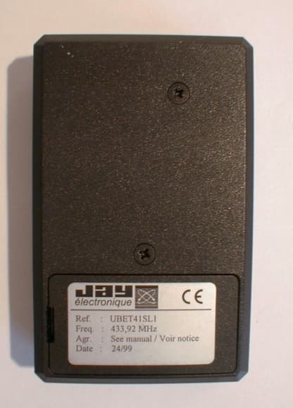
OQMUB1
Oct 17, 1999Radio remote control system - transmitter
Equipment Class
DSC - Part 15 Security/Remote Control Transmitter