OQMUB1Radio remote control system - transmitter
Jay Electronique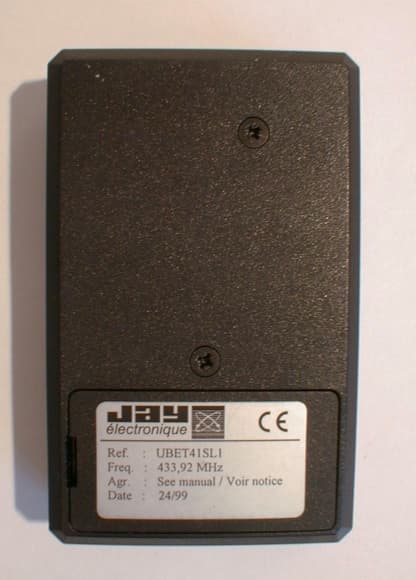
Click to zoom
Application Details
- Equipment Class
- DSC - Part 15 Security/Remote Control Transmitter
- Date of Grant
- Oct 17, 1999
- Application Purpose
- Original Equipment
- Date of Application
- Oct 03, 1999
- Equipment Note
- Radio remote control system - transmitter
- Frequency Range
- 433.92000000 - 433.92000000
- Company
- Jay Electronique
- Country
- France
Documents & Files
Document Text
Text extracted from the exhibit documents filed with the FCC. Open a document above to read the original.
Users Manual
1 ATTACHMENTS : PRODUCT DATA SHEET AND USER MANUAL ATTACHMENT A – PRODUCT DATA SHEET ATTACHMENT B – User Manual
Block Diagram
1 BLOCK DIAGRAM(S) OF EQUIPMENT 1.1 Clock schematics of UBET41SL1 The complete clock system is included in the Radiometrix Ltd TXM-433-A module. Crystal and oscillators : .............................433.92 MHZ, SAW oscillator 2 PRODUCT SCHEMATIC
Cover Letter(s)
1 FCC SUBMISSION FILE JAY ELECTRONIQUE – UBETx1SL1 FCC ID:OQMUB1 September 29, 1999 This report concerns : Original Grant ___X_____Class II change __________ *Subpart C verification ___X____*Class A verification ________ Class I change _______ Equipment type : Radio remote control system – transmitter Request issue of grant : _X_Immediately upon completion of review ___Defer grant per 47 CFR 0.457(d)(1)(ii) until ____ date _____. Company Name agrees to notify the Commission by _____date_____ of the intended date of announcement of the product so that the grant can be issued on that date. Confidentiality of grant : ___Applicant requests the existence of this grant to be kept confidential until ____date____. The announcement of this product before this date via freedom of information would be detrimental to Company Name, and therefore must be considered a business secret. Public announcement of this product will not be made prior to this date. (Max. 60 days after grant issued). Limits used : (check one) CISPR 22 ___________________ Part 15 _________X________ Measurement procedure used is ANSI C63.4-1992 unless another is specified. Other test procedure : ____________________________________________________ Application for verificationApplicant for this device Prepared by : Emmanuel VIGIER JAY ELECTRONIQUE 176 Rue LAVOISIER – ZIRST 2 BP 5 38330 MONTBONNOT SAINT MARTIN – France Ph. : 33 4 76 41 44 00 Fax : 33 4 76 41 44 41 Emmanuel VIGIER JAY ELECTRONIQUE 176 Rue LAVOISIER – ZIRST 2 BP 5 38330 MONTBONNOT SAINT MARTIN – France Ph. : 33 4 76 41 44 00 Fax : 33 4 76 41 44 41 e-mail : [email protected]
External Photos
1 PHOTOS OF TESTED EUT The following photo are attached : 9.1 External view of UBET41SL1 9.2 Bottom view of UBET41SL1 9.3 Internal view of UBRS4L1TR 9.4 Component side of board 1.1 External view of UBET41SL1 1.2 Bottom view of UBET41SL1 1.3 Internal view of UBET41SL1 1.4 Component side of UBET41SL1
ID Label/Location Info
1 PRODUCT LABELING 1.1 FCC ID Label This is the copy of the label stuck on the product 1.2 Location of label on EUT Label is stuck on rear of enclosure, near the serial label. : OQMUB1
ID Label/Location Info
1 PRODUCT LABELING 1.1 FCC ID Label This is the copy of the label stuck on the product 1.2 Location of label on EUT Label is stuck on rear of enclosure, near the serial label. : OQMUB1 : OQMUB1
Operational Description
1 GENERAL INFORMATION 1.1 Product description The UBET*1SL1 is a transmitter used with the UBRS*L1* receiver. It's classified as a periodic transmitter operating in the band 40.66-40.70MHz and above 70MHz, as defined in section 15.231 of FCC Part 15, Subpart C. It provides solutions for a wide range of simple industrial and building automation applications. This series offers a large number of transmitters and receivers providing different types and numbers of functions designed to meet the wide range of user requirements. It incorporates numerous features and significant technological advances : European and American frequencies in the 400MHz band FM Radio link Simultaneous commands Programming of functions using jump switches or microswitches, thus ensuring numerous possibilities (identity codes, operating modes, command interlocking, relay number controlled by the transmitter, button number controlling receiver) depending on model. The UBET*1SL1 covers a complete range of models, which differ only by the number of channels. The tested product (UBET41SL1) is the most complete model (4channels) and it represents the worst case. Other models differ only by removing some components. The transmitter module (included in the product) is a standard commercial module made by RADIOMETRIX Ltd. The reference is TXM-433-A This product is professionally installed. The antenna cannot be changed as it's included on the printed wiring board (15.203 requirement). The emission signal is active only when one (or more) of the button is pressed. As soon as (few milli-second) the button is released, the emission stops (15.231.a requirement). See attachment A for further description and technical features of the product submitted. 1.2 Related Submittal(s) / Grant(s) Equipment is tested as a stand alone system. 1.3 Tested System Details The transmitter has been tested in stand alone mode; One channel button is continuously push to generate the power signal. 1.4 Test Methodology Both conducted and radiated testing were performed according to the procedures in ANSI C63.4-1992, and FCC PART 15, Subpart C, section 15.231. Radiated testing was performed at an antenna to EUT distance of 3 meters. 1.5 Test facility The test facility used to collect the radiated and conducted data is the SMEE Actions Mesures facility located ZI des Blanchisseries, 38500 VOIRON, France. This test facility has been fully described in a report and accepted by FCC as compliant with the radiated and AC line conducted test site criteria in ANSI C63.4-1992 in a letter dated August 04, 1999 (Registration number 94821). This test facility has also been accredited by COFRAC (French accreditation authority for European union test lab accreditation organization), accreditation number 1-0844 as compliant with test site criteria and competence in EN55022/CISPR22 norms for 89/336/EEC European EMC Directive application. All pertinent data for this test facility remains unchanged.
Test Report
1 SYSTEM TEST CONFIGURATION 1.1 Justification The system was configured for testing in a typical fashion (as a customer would normally use it). The worst case product (UBET41SL1), as described in chapter 1.1 of this file, has been tested. No difference have been encountered depending of the functional mode of the product (1, 2, 3 or 4 button used). The worst case position of the transmitter has been fund in vertical position, as shown on photographies. 1.2 EUT Exercise software No software is embedded in the product. 1.3 Special accessories No special accessories were necessary to perform the test. 1.4 Equipment modifications No equipment modification has been necessary during testing to achieve compliance to FCC Part15, Subpart C levels. The unit tested was a production unit. 1.5 Configuration of tested system. Transmitter UBET41SL1 Thi s button conti nuously pressed during the test. 2 RADIATED EMISSION DATA 2.1 Test Procedure (15.231.b) The product has been tested according to ANSI C63.4-1992 and FCC PART15, Subpart C, Section 15.231. In first, the frequencies are identified in the full anechoic chamber and then are measured on the Open Area Test Site. The plots on the following page shown only the frequency identification. The table just after shown the measured levels. Measured levels are in dBμV/m, then they are corrected in μV/m in order to compare them to the FCC limit. The following conversion is used : L (μV/m) = inv log (L(dBμV/m) / 20) The product has been tested at a distance of 3 meters from the antenna and compared to the FCC Part15, Subpart C, limits. Measurement bandwidth was 120 KHz from 30 MHz to 1 GHz and 1 MHz upon 1 GHz. Under 1GHz, measurement are Quasi Peak measurements, according to CISPR requirements. Above 1GHZ, measurement are Peak measurement. All these values being under limits, the average measurement has not been performed. Antenna height search was performed from 0.9m to 4m for both horizontal and vertical polarization. Continuous linear turntable azimuth search was performed with 360 degrees range. A summary of the worst case emissions found in all test configurations and modes is shown on the following page. Test Equipment: HP-8568B Analyzer + HP-85650A Quasi-Peak adapter + HP-85685A RF Preselector HP 8591EM Spectrum analyzer HP 8546A EMI Receiver CHASE CBL6111A Antenna, 30-1000 MHz EMCO 3115 Antenna, 1-18GHZ . 2.2 Radiated emission data (15.231.b) Plot of frequencies from 1 to 5 GHZPlot of frequencies from 200 to 1000 MHZ Final result: Frequency (MHz) Restricted bands Limits (Lmt) (uV/m) Measure* (Mea) (uV/m) Mea-Lmt (μV/m) Angle (deg) PolHgt (cm) Tot Corr (μV/m) Comments 433.92No109966309.6(Q)-4686.410H1159.8 867.8No1099.6147.9(Q)-951.712H14324.5 1301.7Yes500105.9(P)-394.19H13525.4 1735.7No1099.6384.6(P)-71516H15835 2169.6No1099.61047.1(P)-144.621H15141.2 2603.5No1099.61047(P)-52.645V13542.17 3037.4No1099.6237.1(P)-862.518H14458.8 3471.4 3905.3 4339.2 4773.1 Not measurable signals * : (A) denotes an average unit, (Q) denotes a Quasi Peak unit, (P) denotes a peak unit. 2.3 Field Strength Calculation (15.231.b) The field strength is calculated by adding the Antenna Factor and Cable Factor, and subtracting the Amplifier Gain (if any) from the measured reading. The basic equation with a sample calculation is as follow : FS = RA + AF + CF – AG WhereFS = Field Strength RA = Receiver Amplitude AF = Antenna Factor CF = Cable Factor AG = Amplifier Gain Assume a receiver reading of 52.5dBμV is obtained. The antenna factor of 7.4 and a cable factor of 1.1 is added. Tha amplifier gain of 29dB is subtracted, giving a field strength of 32 dBμV/m. FS = 52.5 + 7.4 + 1.1 – 29 = 32 dBμV/m The 32 dBμV/m value can be mathematically converted to its corresponding level in μV/m. Level in μV/m = Common Antilogarithm [(32dBμV/m)/20] = 39.8 μV/m. 2.4 Emission bandwidth (15.231.c) Emission frequency is : 433.92 MHz 0.25% of 433.92 MHz = 1.0848 MHz. Measured bandwidth = 93.8KHz
Test Setup Photos
1 RADIATED MEASUREMENT PHOTO 1.1 Radiated emission
Contact Information
Applicant
Patrick Berthet(Chairman)
Test Firm
LCIE Sud-EstJacques Lorquin
Technical Specifications
| # | Rule Parts | Frequency Range | Power Output | Tolerance |
|---|---|---|---|---|
| 1 | 15C | 433.92 MHz - 433.92 MHz | - | % |
Other Applications from Jay Electronique
OQMKT
May 02, 2023Industrial Remote Controls
Equipment Class
DSC - Part 15 Security/Remote Control Transmitter
OQMKR
May 02, 2023Industrial Remote Controls
Equipment Class
DSC - Part 15 Security/Remote Control Transmitter
OQMS5
May 17, 2021Radio Module 2.4GHz
Equipment Class
DTS - Digital Transmission System