OQSRTU4120AIridium Telephone System
ECI Satellite Communication A/S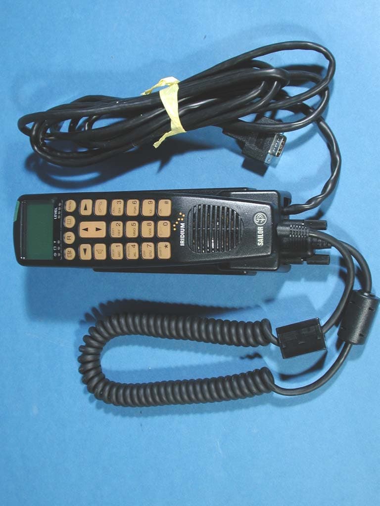
Click to zoom
Application Details
- Equipment Class
- TNB - Licensed Non-Broadcast Station Transmitter
- Date of Grant
- Apr 16, 2003
- Application Purpose
- Original Equipment
- Date of Application
- Apr 16, 2003
- Equipment Note
- Iridium Telephone System
- Frequency Range
- 1616.00000000 - 1626.00000000
- Country
- Denmark
Documents & Files
Document Text
Text extracted from the exhibit documents filed with the FCC. Open a document above to read the original.
Users Manual
List of contents, see page 1. SAILOR SC4150 Operating Instructions ii 0125 iii Handset What Is What? 1. Display 2. Indicator lamps Power Call Network 3. Escape key 4. Call transfer key 5. Loudspeaker on/off key 6. Shift key 7. Lock on/off key 8. On/off button 9. Earpiece 10. Signal level 11. Opens menu 12. Opens phone book 13. Volume control 14. Hook on/off key 15. OK key 16. Loudspeaker 17. Microphone 1 2 3 4 5 6 7 8 9 10 11 12 13 14 15 16 17 0125 iv Introduction Congratulations on your new Iridium equipment. Your Iridium equipment is a modular system that consists of an antenna, transmitter/receiver, control handset and/or fixed control unit, and optional PSTN telephone/PBX. You can operate the Iridium equipment in voice mode from a control handset, fixed control unit, and/or PSTN telephone. To the system you can connect up to four handsets or fixed control units and one PSTN telephone or PBX switchboard. Important! For FCC RF exposure compliance, the antenna must be installed with a minimum distance of 0.61m (2 feet) away from all persons. About this Manual This manual provides instructions on how to operate a control handset and telephone. Basically, the manual consists of two main parts: The first deals with simple operation, which includes e.g. making and answering calls. The second part describes the more advanced functions of the system. All functions of your Iridium equipment can be tested by following the step by step procedures described in this manual. Each procedure is an explicit sequence of key presses that has to be carried out. Unless otherwise specified, the description of the individual proce- dures has been based on the assumption that the CU is enabled and has returned to idle state. See section “Handset Enabling/Disabling” under “Handset Simple Operation” on how to enable and disable the handset. Returning to Idle State on an Enabled CU: 1. Press , if necessary, a number of times until one of the following idle texts are shown in the display: •Ready •Occupied •Internal Call •External Call •Locked and possibly time, date and time or position depending on the status of your Iridium equipment. Alternative idle texts are specified in section “SIM Card Messages” under “SIM Card Handling”. 2. Make sure that the CU is hooked on. Place the handset in the cradle and press if the icon is shown in the display. We recommend that you read the manual before using the equip- ment. Please note Any responsibility or liability for loss or damage in connection with the use of this product and the accompanying documentation is disclaimed. The information in this manual is furnished for informa- tional use only, is subject to change without notice, may contain errors or inaccuracies, and represents no commitment whatsoever. This agreement is governed by the laws of Denmark. Doc. no.: B4150GB0Issue: E/0303 0303 1 Contents Handset................................................................................iii What Is What?............................................................................. iii Introduction......................................................................... iv About this Manual.............................................................. iv Iridium Satellite System...................................................... 1 Abbreviations....................................................................... 1 Using a Telephone............................................................... 2 Handset Simple Operation................................................. 3 Handset States............................................................................. 3 Handset Enabling/Disabling......................................................... 3 Pin Code....................................................................................... 3 Unlocking Handset........................................................................ 3 Call Functions............................................................................... 4 Making a Manual Call................................................................... 5 Answering a Call........................................................................... 6 Call Transfering............................................................................. 6 Transferring AFTER Answering.................................................... 6 Automatic Transferring BEFORE Answering............................... 6 Handset Advanced Operation............................................ 7 Menu System................................................................................ 7 Phone Book ................................................................................... 8 Deleting a Stored Entry in the Phone Book................................. 9 Calling a Number from the Phone Book...................................... 9 Redialling.................................................................................... 10 Security Lock Function............................................................... 10 User ID/User Name List............................................................. 10 Disabling Security Lock.............................................................. 10 Enabling Security Lock............................................................... 11 Password.................................................................................... 11 Users........................................................................................... 12 Call Log....................................................................................... 13 Setting Time and Date................................................................ 14 Setting Dimmer and Contrast..................................................... 15 GPS ............................................................................................. 15 Display........................................................................................ 16 S…
Text truncated - open the document above for the full version.
Users Manual
Operator’sManual Scansat-7701 Telephone System for Maritime Communication SKANTI ii iii Handset What Is What? 1. Display 2. Indicator lamps Power Call In use 3. Escape key 4. Call transfer key 5. Loudspeaker on/off key 6. Shift key 7. Lock on/off key (not yet implemented) 8. On/off button 9. Earpiece 10. Signal level 11. Opens menu 12. Opens address book 13. Volume control 14. Hook on/off key 15. Keypad 16. OK key 17. Loudspeaker 18. Microphone 1 2 3 4 5 6 7 8 9 10 11 12 13 14 15 16 17 18 0125 iv Introduction The SKANTI ® Scansat-7701 is a single-channel Iridium ® satellite system designed for the harsh sea environments with professional mariners and serious yachtsmen in mind. The SKANTI Scansat-7701 conform to all relevant international requirements. The SKANTI Scansat-7701 system consist of a compact Transceiver Unit (ITU 7701), a small Antenna Unit (IAU 7701), and a Control Unit Handset (ICUH 7701). The Control Unit ICUH 7701/ICUD 7701 with display and keypad is used for controlling the "black box" Transceiver Unit and the remote Antenna Unit facilitating installation. The SKANTI Scansat-7701 Iridium telephone offers both telephony and data transmission at 2,400 bit/s. The SKANTI Scansat-7701 Iridium system provides flexible installa- tion: -Up to 100 m between the Control Unit and the Transceiver Unit -Up to 50 m between the Transceiver Unit and the Antenna Unit depending on cable type. The SKANTI Scansat-7701 standard power supply is 10-32 V DC, optionally 110-230 V AC (external adaptor). Important! For FCC RF exposure compliance, the antenna must be installed with a minimum distance of 0.61m (2 feet) away from all persons. About this Manual This manual provides instructions on how to operate a control handset and telephone. Basically, the manual consists of two main parts: The first deals with simple operation, which includes e.g. making and answering calls. The second part describes the more advanced functions of the system. All functions of your Iridium equipment can be tested by following the step by step procedures described in this manual. Each procedure is an explicit sequence of key presses that has to be carried out. Unless otherwise specified, the description of the individual proce- dures has been based on the assumption that the CU is enabled and has returned to idle state. See section “Handset Enabling/Disabling” under “Handset Simple Operation” on how to enable and disable the handset. 0303 Returning to Idle State on an Enabled CU: 1. Press , if necessary, a number of times until one of the following idle texts are shown in the display: • Ready • Occupied • Internal Call • External Call • Locked and possibly time, date and time or position depending on the status of your Iridium equipment. Alternative idle texts are specified in section “SIM Card Messages” under “SIM Card Handling”. 2. Make sure that the CU is hooked on. Place the handset in the cradle and press if the icon is shown in the display. We recommend that you read the manual before using the equip- ment. Please note Any responsibility or liability for loss or damage in connection with the use of this product and the accompanying documentation is disclaimed. The information in this manual is furnished for informa- tional use only, is subject to change without notice, may contain errors or inaccuracies, and represents no commitment whatsoever. This agreement is governed by the laws of Denmark. Doc. no.: B4155GB9 Issue: E/0303 1 Contents Handset................................................................................ iii What Is What?............................................................................. iii Introduction......................................................................... iv About this Manual.............................................................. iv Iridium Satellite System...................................................... 1 Abbreviations....................................................................... 1 Using a Telephone............................................................... 2 Handset Simple Operation................................................. 3 Handset States............................................................................. 3 Handset Enabling/Disabling......................................................... 3 Pin Code....................................................................................... 3 Unlocking Handset........................................................................ 3 Call Functions............................................................................... 4 Making a Manual Call................................................................... 5 Answering a Call........................................................................... 6 Call Transfering............................................................................. 6 Transferring AFTER Answering.................................................... 6 Automatic Transferring BEFORE Answering............................... 6 Handset Advanced Operation............................................ 7 Menu System................................................................................ 7 Phone Book................................................................................... 8 Deleting a Stored Entry in the Phone Book................................. 9 Calling a Number from the Phone Book...................................... 9 Redialling.................................................................................... 10 Security Lock Function............................................................... 10 User ID/User Name List............................................................. 10 Disabling Security Lock.............................................................. 10 Enabling Security Lock............................................................... 11 Password.........................................................…
Text truncated - open the document above for the full version.
Users Manual
IRIDIUM ICHU1000 Operating Instructions Iridium Satellite LLC 8440 South River Parkway Tempe, AZ 85284 USA Tel.Toll Free 1-866-947-4348 Local or International 1-480-752-5155 E-mail [email protected] ii 0125 iii Handset What Is What? 1. Display 2. Indicator lamps Power Call Network 3. Escape key 4. Call transfer key 5. Loudspeaker on/off key 6. Shift key 7. Lock on/off key 8. On/off button 9. Earpiece 10. Signal level 11. Opens menu 12. Opens phone book 13. Volume control 14. Hook on/off key 15. OK key 16. Loudspeaker 17. Microphone 1 2 3 4 5 6 7 8 9 10 11 12 13 14 15 16 17 0125 iv Introduction Congratulations on your new Iridium equipment. Your Iridium equipment is a modular system that consists of an antenna, transmitter/receiver, control handset and/or fixed control unit, and optional PSTN telephone/PBX. You can operate the Iridium equipment in voice mode from a control handset, fixed control unit, and/or PSTN telephone. To the system you can connect up to four handsets or fixed control units and one PSTN telephone or PBX switchboard. Important! For FCC RF exposure compliance, the antenna must be installed with a minimum distance of 0.61m (2 feet) away from all persons. About this Manual This manual provides instructions on how to operate a control handset and telephone. Basically, the manual consists of two main parts: The first deals with simple operation, which includes e.g. making and answering calls. The second part describes the more advanced functions of the system. All functions of your Iridium equipment can be tested by following the step by step procedures described in this manual. Each procedure is an explicit sequence of key presses that has to be carried out. Unless otherwise specified, the description of the individual proce- dures has been based on the assumption that the CU is enabled and has returned to idle state. See section “Handset Enabling/Disabling” under “Handset Simple Operation” on how to enable and disable the handset. Returning to Idle State on an Enabled CU: 1. Press , if necessary, a number of times until one of the following idle texts are shown in the display: •Ready •Occupied •Internal Call •External Call •Locked and possibly time, date and time or position depending on the status of your Iridium equipment. Alternative idle texts are specified in section “SIM Card Messages” under “SIM Card Handling”. 2. Make sure that the CU is hooked on. Place the handset in the cradle and press if the icon is shown in the display. We recommend that you read the manual before using the equip- ment. Please note Any responsibility or liability for loss or damage in connection with the use of this product and the accompanying documentation is disclaimed. The information in this manual is furnished for informa- tional use only, is subject to change without notice, may contain errors or inaccuracies, and represents no commitment whatsoever. This agreement is governed by the laws of Denmark. Doc. no.: B4150GB1Issue: C/0303 0303 1 Contents Handset................................................................................iii What Is What?............................................................................. iii Introduction......................................................................... iv About this Manual.............................................................. iv Iridium Satellite System...................................................... 1 Abbreviations....................................................................... 1 Using a Telephone............................................................... 2 Handset Simple Operation................................................. 3 Handset States............................................................................. 3 Handset Enabling/Disabling......................................................... 3 Pin Code....................................................................................... 3 Unlocking Handset........................................................................ 3 Call Functions............................................................................... 4 Making a Manual Call................................................................... 5 Answering a Call........................................................................... 6 Call Transfering............................................................................. 6 Transferring AFTER Answering.................................................... 6 Automatic Transferring BEFORE Answering............................... 6 Handset Advanced Operation............................................ 7 Menu System................................................................................ 7 Phone Book ................................................................................... 8 Deleting a Stored Entry in the Phone Book................................. 9 Calling a Number from the Phone Book...................................... 9 Redialling.................................................................................... 10 Security Lock Function............................................................... 10 User ID/User Name List............................................................. 10 Disabling Security Lock.............................................................. 10 Enabling Security Lock............................................................... 11 Password.................................................................................... 11 Users........................................................................................... 12 Call Log....................................................................................... 13 Setting Time and Date................................................................ 14 Setting Dimmer and Contrast..................................................... 15 GPS ..................................................................…
Text truncated - open the document above for the full version.
Users Manual
SAILOR SC4150 Installation Manual Single-channel Unit Introduction Congratulations on your new Iridium handset or PSTN (Public Switched Telephone Network) telephone. Your Iridium system is a modular system that consists of an antenna, transmitter/receiver, handset and optional PSTN telephone/PBX (Private Branch Exchange) switchboard. You can operate the Iridium system in voice mode from a handset and/or PSTN telephone. To the system you can connect up to five handsets and one PSTN telephone or PBX switchboard. Sailor marine equipment is specially designed for the extremely rugged conditions on board a ship, based on more than 50 years of experience with all kinds of boats, from small pleasure crafts, over fishing boats working under all climatic conditions, to the biggest ships. EuroCom Industries A/S (ECI) develops and produces high- technology maritime communications equipment under the brandname Sailor . ECI is one of the world’s largest suppliers of communications equipment for the maritime segment, a position which has been maintained by means of constant and extensive product develop- ment. The Sailor products are sold through a global network with more than 60 qualified and trained distributors. Please note Any responsibility or liability for loss or damage in connection with the use of this product and the accompanying documentation is disclaimed. The information in this manual is furnished for informa- tional use only, is subject to change without notice, may contain errors or inaccuracies, and represents no commitment whatsoever. This agreement is governed by the laws of Denmark. Doc. no.: M4150GB0Issue: G/0303 1 Installation IRIDIUM 0225 Contents 1Configuration of Single-Channel Unit .............................................................................................................. 2 2Installation .......................................................................................................................................................... 3 2.1Cable Overview .................................................................................................................................................... 3 2.1.1 Scanbus Termination ............................................................................................................................................ 5 2.2Where to Place the Satellite Transceiver Box ..................................................................................................... 7 2.3How to Mount the Satellite Transceiver Box ........................................................................................................ 8 2.4How to Put on the Finishing Cover ...................................................................................................................... 9 2.5How to Insert the SIM Card .................................................................................................................................. 10 2.6How to Remove the Finishing Cover ................................................................................................................... 11 2.7Installation of the Antenna .................................................................................................................................... 12 2.8PABX/PSTN Interface .......................................................................................................................................... 15 2.9Data Interface ....................................................................................................................................................... 15 Appendix A ..................................................................................................................................................................... 17 Spareparts List ..................................................................................................................................................... 17 2 Installation IRIDIUM 0225 1 Configuration of Single-Channel Unit L1 35423E 10 - 32V DC PABX Phone DTE 2 3 41 Antenna Unit Max. cable loss 3dB Iridium L1 + L2 < 100 metres L2 Box Connection 5 1 Handset Control Handset Transceiver Unit Control 6 GPS 3 Installation IRIDIUM 2 Installation 2.1Cable Overview Cable 1 Scanbus Cable:9*0.22 mm 2 shielded shield connected to ground Cable connector type:9 pole sub-d male TransceiverDescriptionHandsetColour 1NC1 2data+2whiteTwisted 3data-3brownpairs 4AF+4greenTwisted 5AF-5yellowpairs 6GND6greyTwisted 7+24V DC7pinkpairs 8RX_AF+8 blue Twisted 9RX_AF-9redpairs shieldGNDshield 2 3 4 5 6 7 8 9 1 10 36088 Cable 2 Phone Cable connector type: RJ 11 TransceiverDescriptionVeritas 1NC1 2phone1+2 3phone1-3 4NC4 Cable 3 Data Cable:9*0.22 mm 2 shielded shield connected to ground Cable connector type:9 pole sub-d male 0225 4 Installation IRIDIUM 0225 TransceiverDescriptionVeritas 1DCD1 2received data2 3transmitted data3 4data terminal ready4 5serial GND5 6data set ready6 7request to send7 8clear to send8 9RI9 shieldGNDshield Cable 4 Power supply Front view Pin no.DescriptionColour 110-32V DCred 20V DCblack 3NCwhite 4GNDgreen 4 3 1 2 36662A Cable 5 Description of connections to T-connection H4196 The wire terminal blocks are connected in parallel. 36090 5 Installation IRIDIUM Cable 6 GPS input Cable:9*0.22 mm 2 shielded shield connected to ground Cable connector type:9 pole sub-d male TransceiverDescriptionVeritas 1NC*1 2PC Rx (RS232)2 3PC Tx (RS232)3 4NC*4 5GND (RS232)5 6NC*6 7NMEA+7 8NMEA-8 9NC*9 shieldGNDshield * Do only connect a standard RS232 terminal cable. If only NMEA needed, then do not connect to other pins than 7 and 8. 2.1.1 Scanbus Termination The scanbus connectiong the transceiver and the control units, has to be terminated. Only the first and last unit on the bus shall have the termination in ON position. The termination in the transceiver unit is done by setting the jumper S3, located near the scanbus terminal on the PCB (see figure below)…
Text truncated - open the document above for the full version.
Users Manual
Scansat-7701 Telephone System for Maritime Communication InstallationManual Introduction The SKANTI ® Scansat-7701 is a single-channel Iridium ® satellite system designed for the harsh sea environments with professional mariners and serious yachtsmen in mind. The SKANTI Scansat-7701 conform to all relevant international requirements. The SKANTI Scansat-7701 system consist of a compact Transceiver Unit (ITU 7701), a small Antenna Unit (IAU 7701), and two types of control units: a Control Unit Handset (ICUH 7701) and a Control Unit for Desk mounting (ICUD 7701). The Control Unit ICUH 7701/ICUD 7701 with display and splash- proof keypad is used for controlling the "black box" Transceiver Unit and the remote Antenna Unit facilitating installation. The SKANTI Scansat-7701 Iridium telephone offers both telephony and data transmission at 2,400 bit/s. A dedicated 'Alert' button for emergency situations is integrated in the Control Unit for dialling the nearest Iridium Gateway, which will route the call to any RCC (Rescue Co- ordinating Centre) selected. The SKANTI Scansat-7701 Iridium system provides flexible installa- tion: -Up to 50 m between the Control Unit and the Transceiver Unit -Up to 100 m between the Handset Control Unit and extra Handset Control Units -Up to 30 m between the Transceiver Unit and the Antenna Unit depending on cable type. The SKANTI Scansat-7701 standard power supply is 10-32V DC, optionally 110-230 V AC (external adaptor). Please note Any responsibility or liability for loss or damage in connection with the use of this product and the accompanying documentation is disclaimed. The information in this manual is furnished for informa- tional use only, is subject to change without notice, may contain errors or inaccuracies, and represents no commitment whatsoever. This agreement is governed by the laws of Denmark. Doc. no.: M4155GB9Issue: G/0303 1 Installation IRIDIUM 0225 Contents 1Configuration of Single-Channel Unit .............................................................................................................. 2 2Installation .......................................................................................................................................................... 3 2.1Cable Overview .................................................................................................................................................... 3 2.1.1 Scanbus Termination ............................................................................................................................................ 5 2.2Where to Place the Satellite Transceiver Box ..................................................................................................... 7 2.3How to Mount the Satellite Transceiver Box ........................................................................................................ 8 2.4How to Put on the Finishing Cover ...................................................................................................................... 9 2.5How to Insert the SIM Card .................................................................................................................................. 10 2.6How to Remove the Finishing Cover ................................................................................................................... 11 2.7Installation of the Antenna .................................................................................................................................... 12 2.8PABX/PSTN Interface .......................................................................................................................................... 15 2.9Data Interface ....................................................................................................................................................... 15 Appendix A ..................................................................................................................................................................... 17 Spareparts List ..................................................................................................................................................... 17 2 Installation IRIDIUM 0225 1 Configuration of Single-Channel Unit L1 35423E 10 - 32V DC PABX Phone DTE 2 3 41 Antenna Unit Max. cable loss 3dB Iridium L1 + L2 < 100 metres L2 Box Connection 5 1 Handset Control Handset Transceiver Unit Control 6 GPS 3 Installation IRIDIUM 2 Installation 2.1Cable Overview Cable 1 Scanbus Cable:9*0.22 mm 2 shielded shield connected to ground Cable connector type:9 pole sub-d male TransceiverDescriptionHandsetColour 1NC1 2data+2whiteTwisted 3data-3brownpairs 4AF+4greenTwisted 5AF-5yellowpairs 6GND6greyTwisted 7+24V DC7pinkpairs 8RX_AF+8 blue Twisted 9RX_AF-9redpairs shieldGNDshield 2 3 4 5 6 7 8 9 1 10 36088 Cable 2 Phone Cable connector type: RJ 11 TransceiverDescriptionVeritas 1NC1 2phone1+2 3phone1-3 4NC4 Cable 3 Data Cable:9*0.22 mm 2 shielded shield connected to ground Cable connector type:9 pole sub-d male 0225 4 Installation IRIDIUM 0225 TransceiverDescriptionVeritas 1DCD1 2received data2 3transmitted data3 4data terminal ready4 5serial GND5 6data set ready6 7request to send7 8clear to send8 9RI9 shieldGNDshield Cable 4 Power supply Front view Pin no.DescriptionColour 110-32V DCred 20V DCblack 3NCwhite 4GNDgreen 4 3 1 2 36662A Cable 5 Description of connections to T-connection H4196 The wire terminal blocks are connected in parallel. 36090 5 Installation IRIDIUM Cable 6 GPS input Cable:9*0.22 mm 2 shielded shield connected to ground Cable connector type:9 pole sub-d male TransceiverDescriptionVeritas 1NC*1 2PC Rx (RS232)2 3PC Tx (RS232)3 4NC*4 5GND (RS232)5 6NC*6 7NMEA+7 8NMEA-8 9NC*9 shieldGNDshield * Do only connect a standard RS232 terminal cable. If only NMEA needed, then do not connect to other pins than 7 and 8. 2.1.1 Scanbus Termination The scanbus connectiong the transceiver and the control units, …
Text truncated - open the document above for the full version.
Contact Information
Applicant
Helge Hoff(Engineer)
Technical Specifications
| # | Rule Parts | Frequency Range | Power Output | Emission | Tolerance |
|---|---|---|---|---|---|
| 1 | 25 | 1.62 GHz - 1.63 GHz | 7 W | 41K7Q7W | 10.0000000000 ppm |
Other Applications from ECI Satellite Communication A/S
OQSECIST4120
Feb 29, 2000Irridium telephone set
Equipment Class
TNB - Licensed Non-Broadcast Station Transmitter