OQYDB100RSecurity Receiver
RHK Technology Inc.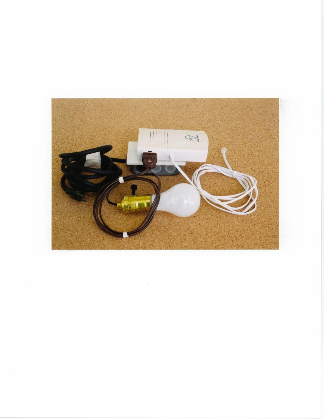
Click to zoom
Application Details
- Equipment Class
- CYY - Communications Receiver used w/Pt 15 Transmitter
- Date of Grant
- Nov 01, 2000
- Application Purpose
- Original Equipment
- Date of Application
- Oct 17, 2000
- Equipment Note
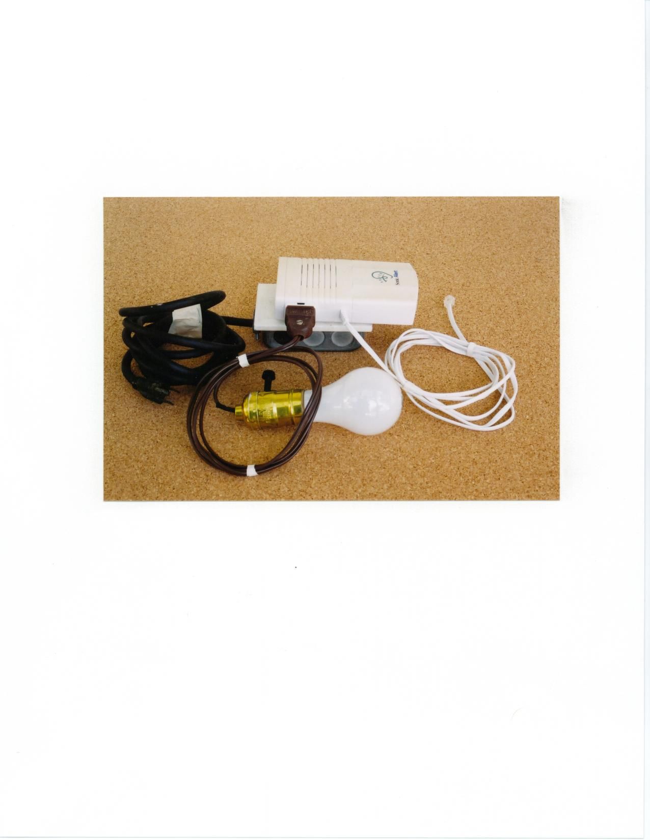
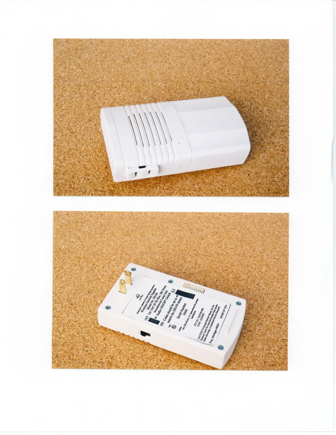
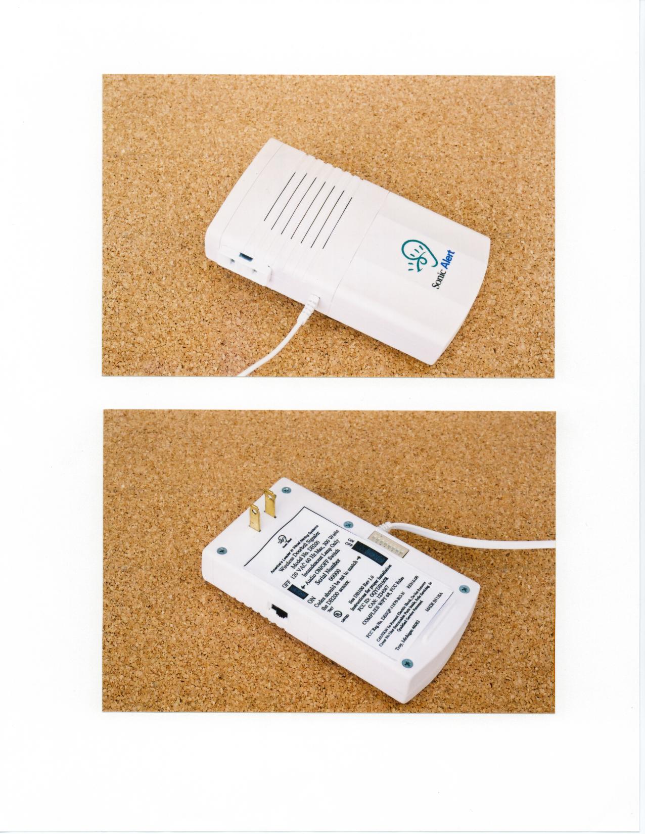
- Security Receiver
- Frequency Range
- 315.00000000 - 315.00000000
- Company
- RHK Technology Inc.
- Country
- United States
Documents & Files
Document Text
Text extracted from the exhibit documents filed with the FCC. Open a document above to read the original.
Operational Description
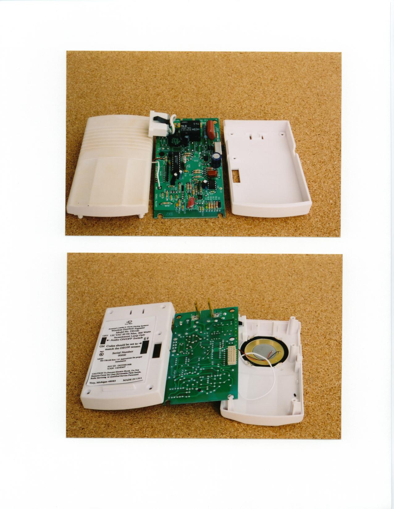
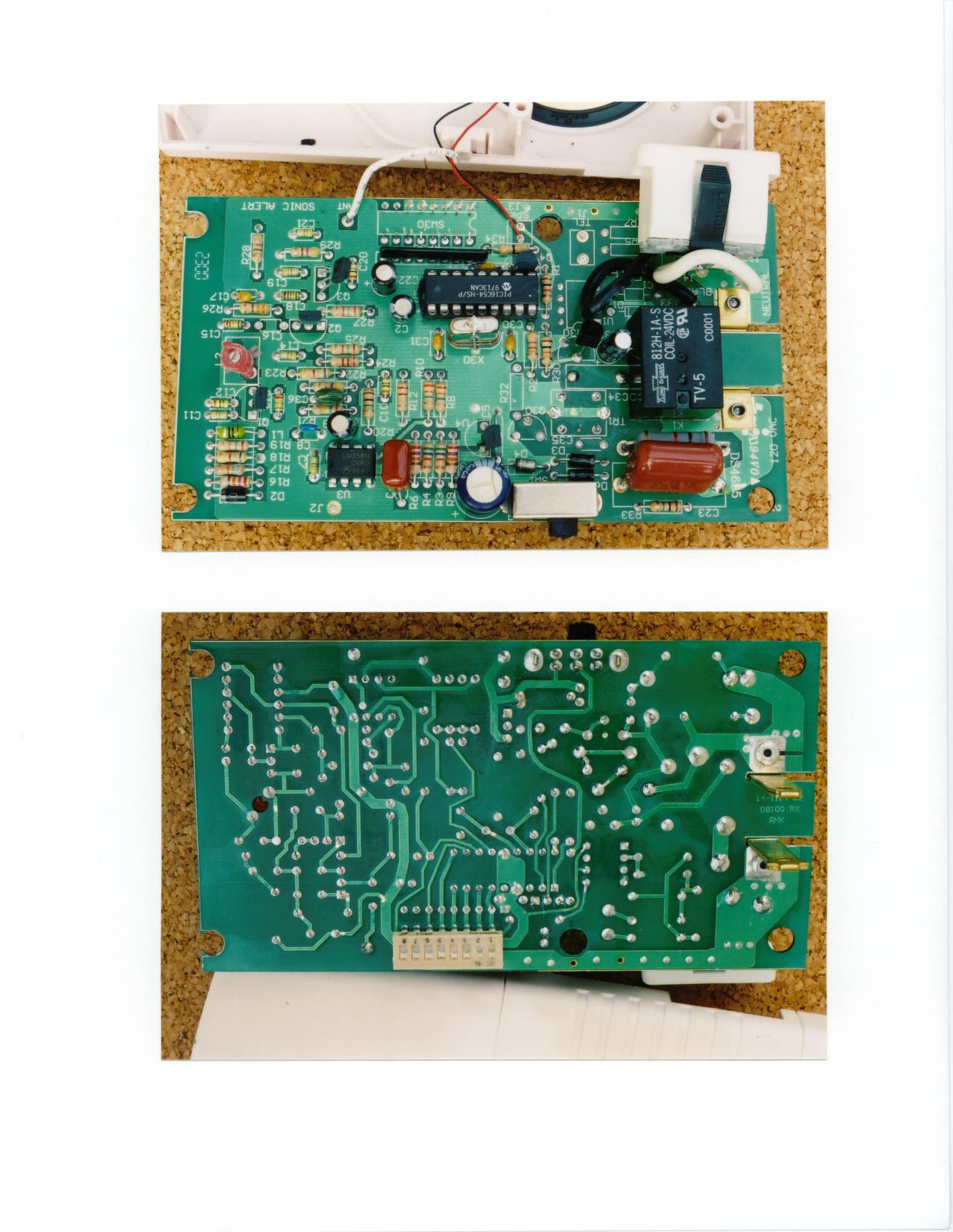
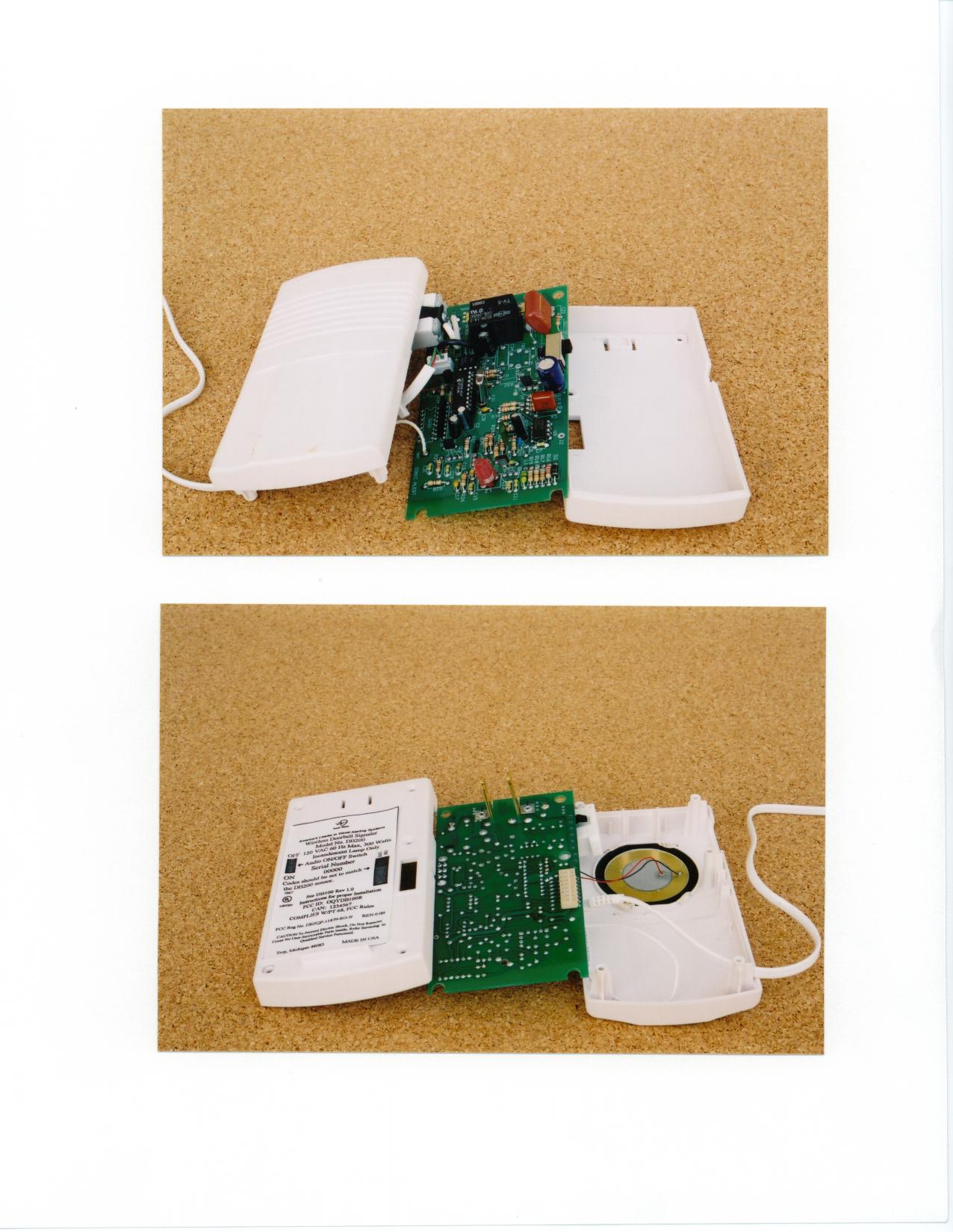
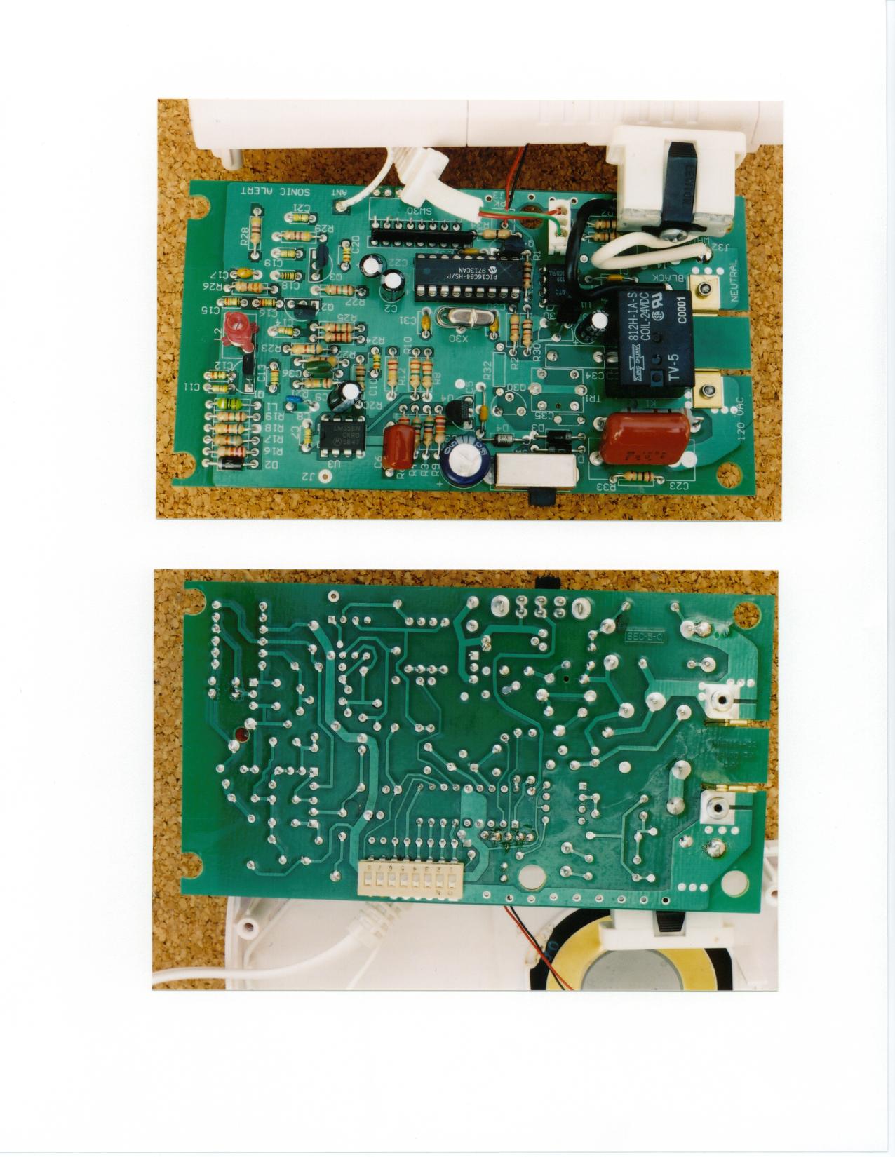
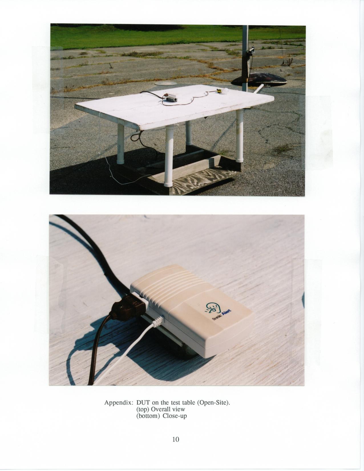
Description of Operation for the DB100/DB200 receiver The DB100/DB200 receiver RF circuitry is designed around a 2 transistor cascode RF amplifier input stage, followed by a super regenerative detector stage amplifier and level shifter to output logic level signals to the microcontroller. The micro accepts input signals from the RF circuitry, and in the case of the DB200 it also accepts input from the telephone line “ring” signal via opto isolation circuitry. The micro processes the decoded input signals and outputs control signals to drive a piezo annunciator and toggle an output relay, which in turn flashes an external lamp.
Contact Information
Applicant
Bryan Bartneck(President)
Technical Contact
University Of Michigan / EECSValdis V Liepa
[email protected]734-483-4211
Ann Arbor, Michigan · United States
Non-Technical Contact
University of Michigan / EECSValdis V Liepa
[email protected]734-483-4211
Test Firm
University of MichiganValdis Liepa
Technical Specifications
| # | Rule Parts | Frequency Range | Power Output |
|---|---|---|---|
| 1 | 15B | 315 MHz - 315 MHz | - |
Other Applications from RHK Technology Inc.
OQYHA360M
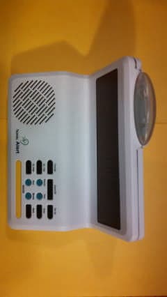
Nov 03, 2014Home Aware Main Unit signaling system for the Deaf
Equipment Class
DXT - Part 15 Low Power Transceiver, Rx Verified
OQYHA360DB
Sep 30, 2014Wireless Doorbell Signaling Device
Equipment Class
DXT - Part 15 Low Power Transceiver, Rx Verified
OQYHA360SS
Sep 29, 2014Wireless Sound Signaling Device
Equipment Class
DXT - Part 15 Low Power Transceiver, Rx Verified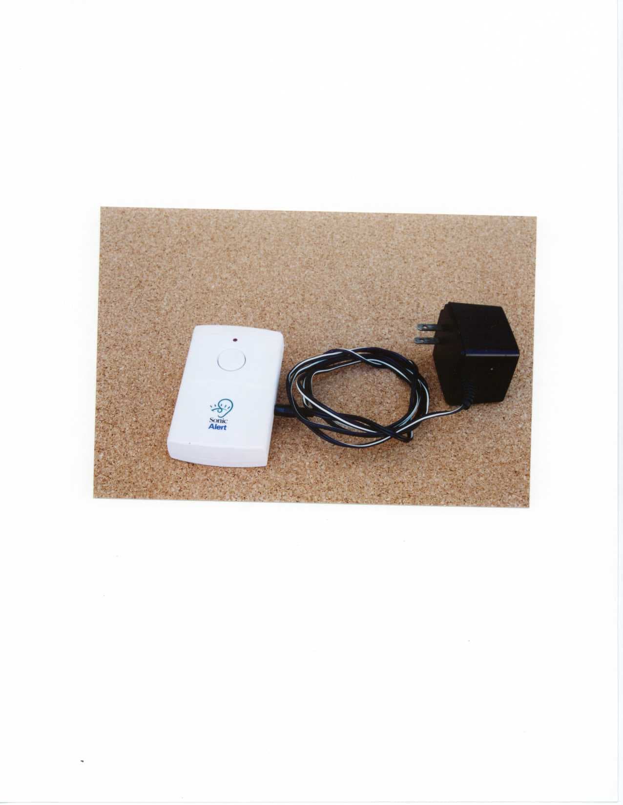
OQYDB100T
Dec 19, 2000Sonic Alert Transmitter
Equipment Class
DSC - Part 15 Security/Remote Control Transmitter