OR8-T1Bluetooth Headphone
Microlab Electronics Co.,Ltd.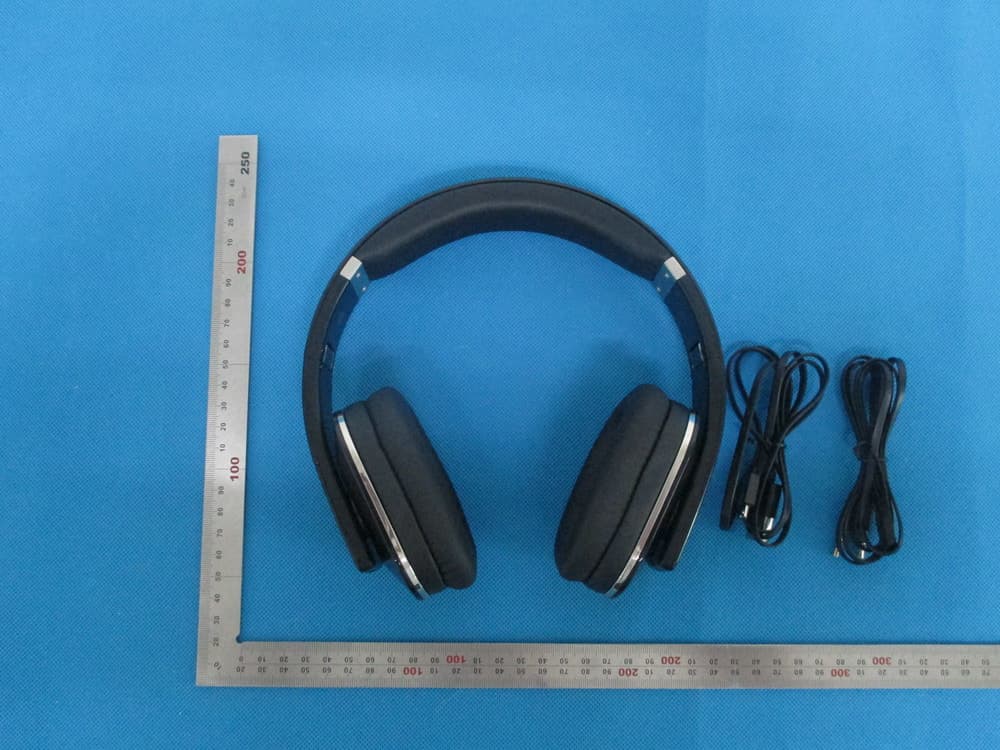
Click to zoom
Application Details
- Equipment Class
- DSS - Part 15 Spread Spectrum Transmitter
- Date of Grant
- Jul 28, 2014
- Application Purpose
- Original Equipment
- Date of Application
- Jul 28, 2014
- Equipment Note
- Bluetooth Headphone
- Frequency Range
- 2402.00000000 - 2480.00000000
- Country
- China
Documents & Files
Document Text
Text extracted from the exhibit documents filed with the FCC. Open a document above to read the original.
Users Manual
T1 Bluetooth Headphone FCC ID:OR8-T1 Important Safety Instructions Caution: To reduce the risk of electric shock, do not dismantle the product and do not expose the apparatus to rain or moisture. No user-serviceable parts inside. Refer servicing to qualified personnel only. The lightning flash within an equilateral triangle is intended to alert you to the presence of uninsulated dangerous voltage within the product's enclosure that may be of sufficient magnitude to constitute an electric shock to a person or persons. The exclamation point within an equilateral triangle is intended to alert you to the presence of important operating and maintenance (servicing) instructions in the literature accompanying the product. Explanation of Graphical Symbols: WARNINGS: 1. Read Instructions - All the safety and operating instructions must be read before the product is operated. 2. Retain Instructions - The safety and operating instructions should be kept product for future reference. 3. Heed warnings - All warnings on the product and in the operating instructions should be adhered to. 4. Follow instructions - All operating and users’ instructions should be followed. 5. Installation - Install in accordance with the manufacturers’ instructions. 6. Power sources - This product should be operated only from the type of power source indicated by the marking adjacent to the power cord entry. If you are not sure of the type of power supply to your home, consult your product dealer or local power company. 7. Grounding or polarization - the product is not required to be grounded. Ensure the plug is fully inserted into the wall outlet or extension cord receptacle to prevent blade or pin exposure. Some versions of the product are equipped with a power cord fitted with a polarized alternating line plug (a plug having one blade wide than the other). This plug will fit onto the power outlet only one way. This is a safety feature. If you are unable to insert the plug fully into the outlet, try reversing the plug. If the plug should still fail to fit, contact your electrician to replace your obsolete outlet. Do not defeat the safety purpose of the polarized plug. When using an extension power-supply cord or a power-supply cord other than that supplied with the appliance, it should be fitted with the appropriate molded plugs and carry safety approval appropriate to the country of use. 8. Power cord protection - Power-supply cords should be routed so that they are not likely to be walked on, kinked or pinched by items placed on or against them, paying particular attention to cords from plugs, receptacles and the point where they exit from the appliance. 9. Overloading - Do not overload wall outlets, extension cords or multiple sockets, as this can result in a risk of fire or electric shock. 10. Ventilation - The product must be properly ventilated. Do not place the product on a bed, sofa, or other similar surface. Do not cover the product with any items such as tablecloths, newspapers, etc. 11. Heat - The product should be situated away from heat sources such as radiators, heat registers, stoves, or other products including amplifiers that produce heat. No naked flame sources, such as lighted candles, should be placed on the apparatus. 12. Water and moisture - To reduce the risk of fire or electric shock, do not expose the product to train, dripping, splashing or excessive moisture such as in a sauna or bathroom. Do not use this product near water for example, near a bathtub, washbowl, kitchen sink, laundry tub, in a wet basement, or near a swimming pool and the like. EN 1 13. Object and Liquid Entry - Never push objects of any kind into this product through openings, as they may touch dangerous voltage points or short-circuit parts that could result in a fire or electric shock. Never spill liquid of any kind on the product. Do not place any object containing liquid on top of the product. 14. Cleaning - Unplug the product from the wall outlet before cleaning. The cabinet of the subwoofer may be cleaned by dusting with a dry cloth. If you wish to use an aerosol cleaning spray, do not spray directly on the cabinet; spray onto the cloth. Be careful not to damage the drive units. 15. Attachments - Do not use attachments not recommended by the product manufacturers, as they may cause hazards. 16. Accessories - Do not place this product on an unstable cart, stand, tripod, bracket or table. The product may fall, causing serious injury to a child or adult, and serious damage to the product. Use only with a cart, stand, tripod, bracket or table recommended by the manufacturer or sold with the product. Any mounting of the product should follow the manufacturer's instructions and should use a mounting accessory recommended by the manufacturer. 17. Moving the product - A product and cart combination should be moved with care. Quick stops, excessive force and uneven surfaces may cause the product and cart combination to overturn. 18. Unused periods - The power cord of the appliance should be unplugged from the outlet during lightning storms or when the apparatus is left unused for a long period of time. 19. Servicing - Do not attempt to service this product yourself, as opening or removing covers may expose you to dangerous voltage or other hazards. Refer all servicing to qualified service personnel. 20. Please remove the power plug form the main power source or wall power source when not in use. When plugged in to a power source, the system is in standby mode, so the power is not entirely cut off. 21. Replacement parts - When replacement parts are required, ensure the service technician has used replacement parts specified by the manufacturer or have the same characteristics as the original part. Unauthorized substitutions may result in fire, electric shock or other hazards. 22. Mains fuses - For continued protection against fire hazard, use fuses only of the correct type and rating. The correct fuse specification for each voltag…
Text truncated - open the document above for the full version.
External Photos
External Photos TOP VIEW OF EUT BOTTOM VIEW OF EUT FRONT VIEW OF EUT BACK VIEW OF EUT LEFT VIEW OF EUT RIGHT VIEW OF EUT
ID Label/Location Info
FCC ID Label Location Bluetooth Headset Model: T1 Brand name:microlab FCC ID: OR8-T1
Internal Photos
Internal Photos OPEN VIEW OF EUT OPEN VIEW OF EUT-1 INTERNAL VIEW OF EUT-1 INTERNAL VIEW OF EUT-2 BT Antenna INTERNAL VIEW OF EUT-2 INTERNAL VIEW OF EUT-3
Test Report
Report No.: AGC01974140603FE03 Page 1 of 70 FCC Test Report Report No.: AGC01974140603FE03 FCC ID : OR8‐T1 APPLICATION PURPOSE : Original Equipment PRODUCT DESIGNATION : Bluetooth Headphone BRAND NAME : microlab MODEL NAME : T1 CLIENT : Microlab Electronics Co.,Ltd. DATE OF ISSUE : Jul.11, 2014 STANDARD(S) : FCC Part 15 Rules REPORT VERSION : V1.0 Attestation of Global Compliance (Shenzhen) Co., Ltd CAUTION: This report shall not be reproduced except in full without the written permission of the test laboratory and shall not be quoted out of context. Report No.: AGC01974140603FE03 Page 2 of 70 Report Revise Record Report Version Revise Time Issued Date Valid VersionNotes V1.0 / Jul.11, 2014 Valid Original Report Report No.: AGC01974140603FE03 Page 3 of 70 TABLE OF CONTENTS 1. VERIFICATION OF CONFORMITY ...................................................................................... 5 2. GENERAL INFORMATION .................................................................................................. 6 2.1. PRODUCT DESCRIPTION ........................................................................................................... 6 2.2. TABLE OF CARRIER FREQUENCYS .......................................................................................... 6 2.3. RECEIVER INPUT BANDWIDTH ................................................................................................. 7 2.4. EXAMPLE OF A HOPPING SEQUENCY IN DATA MODE ........................................................... 7 2.5. EQUALLY AVERAGE USE OF FREQUENCIES AND BEHAVIOUR ............................................ 7 2.6. RELATED SUBMITTAL(S) / GRANT (S) ....................................................................................... 8 2.7. TEST METHODOLOGY................................................................................................................ 8 2.8. SPECIAL ACCESSORIES ............................................................................................................ 8 2.9. EQUIPMENT MODIFICATIONS ................................................................................................... 8 3. MEASUREMENT UNCERTAINTY........................................................................................ 9 4. DESCRIPTION OF TEST MODES ........................................................................................ 9 5. SYSTEM TEST CONFIGURATION .................................................................................... 10 5.1. CONFIGURATION OF EUT SYSTEM ........................................................................................ 10 5.2. EQUIPMENT USED IN EUT SYSTEM ....................................................................................... 10 5.3. SUMMARY OF TEST RESULTS ................................................................................................ 10 6. TEST FACILITY .................................................................................................................. 11 7. PEAK OUTPUT POWER .................................................................................................... 12 7.1. MEASUREMENT PROCEDURE ................................................................................................ 12 7.2. TEST SET-UP (BLOCK DIAGRAM OF CONFIGURATION) ....................................................... 12 7.3. LIMITS AND MEASUREMENT RESULT .................................................................................... 13 8. 20DB BANDWIDTH ............................................................................................................ 19 8.1. MEASUREMENT PROCEDURE ................................................................................................ 19 8.2. TEST SET-UP (BLOCK DIAGRAM OF CONFIGURATION) ....................................................... 19 8.3. LIMITS AND MEASUREMENT RESULTS .................................................................................. 19 9. CONDUCTED SPURIOUS EMISSION ............................................................................... 26 9.1. MEASUREMENT PROCEDURE ................................................................................................ 26 9.2. TEST SET-UP (BLOCK DIAGRAM OF CONFIGURATION) ....................................................... 26 9.3. MEASUREMENT EQUIPMENT USED ....................................................................................... 26 9.4. LIMITS AND MEASUREMENT RESULT .................................................................................... 26 10. RADIATED EMISSION ..................................................................................................... 33 10.1. MEASUREMENT PROCEDURE .............................................................................................. 33 10.2. TEST SETUP ............................................................................................................................ 35 10.3. TEST RESULT (Worst Modulation: GFSK) ............................................................................... 36 Report No.: AGC01974140603FE03 Page 4 of 70 11. BAND EDGE EMISSION .................................................................................................. 48 11.1. MEASUREMENT PROCEDURE .............................................................................................. 48 11.2. TEST SET-UP ........................................................................................................................... 48 11.3. TEST RESULT .......................................................................................................................... 49 12. NUMBER OF HOPPING FREQUENCY ............................................................................ 53 12.1. MEASUREMENT PROCEDURE .............................................................................................. 53 12.2. TEST SETUP (BLOCK DIAGRAM OF CONFIGURATION) ........…
Text truncated - open the document above for the full version.
Test Setup Photos
APPENDIX IV PHOTOGRAPHS OF TEST SETUP FCC LINE CONDUCTED EMISSION TEST SETUP FCC RADIATED EMISSION TEST SETUP
Contact Information
Applicant
Xueyuan Bai
Test Firm
Attestation of Global Compliance Shenzhen Co. Ltd.Forrest Lei
Technical Specifications
| # | Rule Parts | Frequency Range | Power Output |
|---|---|---|---|
| 1 | 15C | 2.40 GHz - 2.48 GHz | 2.50 mW |
Other Applications from Microlab Electronics Co.,Ltd.

OR8-M-113BT
Sep 28, 2014MULTIMEDIA SPEAKER
Equipment Class
DXX - Part 15 Low Power Communication Device Transmitter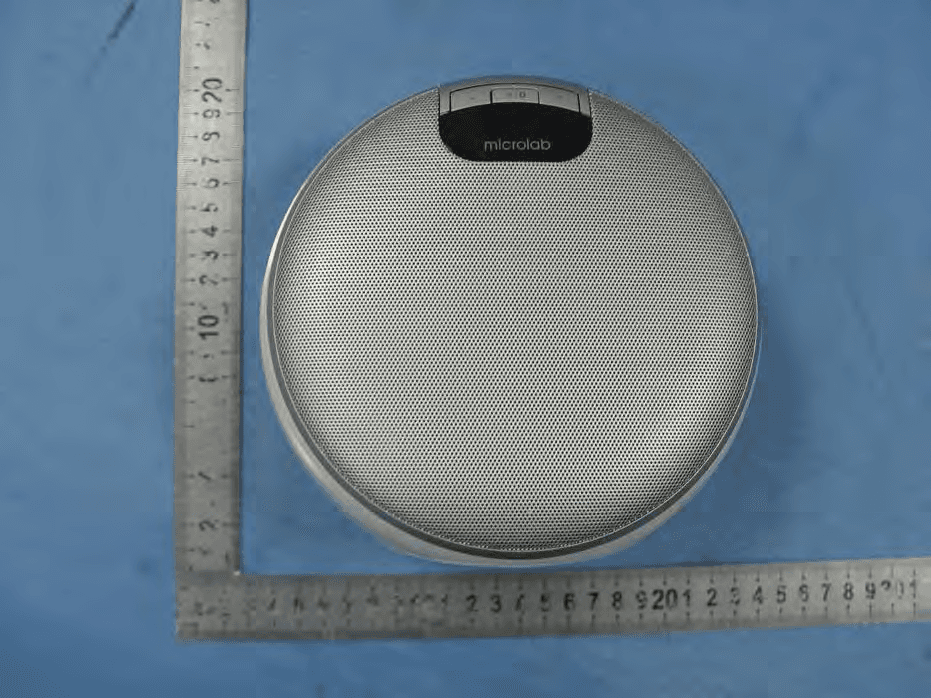
OR8-MD312
Dec 12, 2012MULTIMEDIA SPEAKER
Equipment Class
DSS - Part 15 Spread Spectrum Transmitter
OR8-MD212
Dec 07, 2012MULTIMEDIA SPEAKER
Equipment Class
DSS - Part 15 Spread Spectrum Transmitter