OSDMCWDTUADigital Wireless Conferencing Unit
Beyerdynamic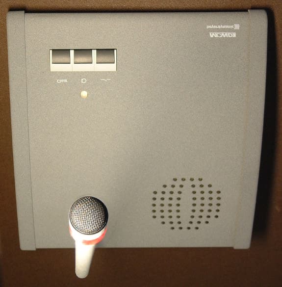
Click to zoom
Application Details
- Equipment Class
- DSS - Part 15 Spread Spectrum Transmitter
- Date of Grant
- May 05, 2002
- Application Purpose
- Original Equipment
- Date of Application
- May 05, 2002
- Equipment Note
- Digital Wireless Conferencing Unit
- Frequency Range
- 2400.00000000 - 2483.50000000
- Company
- Beyerdynamic
- Country
- United States
Documents & Files
Document Text
Text extracted from the exhibit documents filed with the FCC. Open a document above to read the original.
Users Manual
16 OPERATING INSTRUCTIONS MCW DIGITAL Thank you for selecting the MCW Digital wireless conference system. Please take some time to read carefully through this manual before setting up the equipment. 1.MCW-D 100 Control Unit 1.1 Controls and Indicators Front view (1)Power LED. LED is illuminated green when the unit is switched on. (2)Standby button. When this button is pressed for more than 3 seconds all switched-on microphone units are switched off. (3)Reset. This button resets the system into the switch-on state (to press the reset button use a paper clip). (4)LEDs to indicate the status of the receiving channels. LED is illuminated green: the channel is vacant. LED is illuminated red: the channel is occupied. Standard configuration: Channel 1 is used for data communication. Channel 2 to 7 for delegates, channel 8 for the chairman. Rear view (5)Connection for receiving antenna A/B (N-connector) (6)Fuse (7)Mains supply (8)On/Off-switch (9)RS 232 port for the connection of PC or media control system (10) Master Out, 3-pin XLR male, balanced, for the connection of external devices such as mixing consoles or sound contracting system (11) Aux 1 Input, 3-pin XLR female, balanced, for the connection of external sound sources or as Insert Return (12) Connection for transmitting antenna (N-connector) (13) Level control for Master Out, RCA (14) Master Out, RCA, unbalanced, for the connection of external devices such as mixing consoles, sound contracting systems or recorder (L + R) (15) Aux 2 Input, RCA, unbalanced, for the connection of external devices such as CD-player (L + R) (16) Level control for Aux 2 Input, RCA As an option there are PCBs available for the connection of e.g. automatic mixers. (17) (Analogue, individual input/output (2 x 25-pin Sub-D) for e.g. interpreting applications and for individual transmitting/receiving signals) (18) (Digital Input/Output, AES/EBU (XLR) and S/PDIF (RCA)). (1)(2)(3)(4) (5)(6)(7)(8)(9)(10)(11)(12)(13)(14)(15)(16)(17)(18)(18)(5) 17 english 1.2 Setting up 1. Place the MCW-D 100 control unit in the same room as the transmitters. 2. Do not place the MCW-D 100 control unit near digitally controlled equipment. 3. Connect the receiving antennae to the antenna inputs A and B (5) using the appropriate adapter. For stand-alone-operation we recommend using the CA 2411 angled rod antenna and the CA 2444 N(HF) Male - SMA Female adapter. 4. Connect the transmitting antenna to the antenna output (12). For stand-alone-operation we recommend using the CA 2411 angled rod antenna and the CA 2444 N(HF) Male - SMA Female adapter. 5. There must be an unobstructed path between the microphone units and the antennae. The range is around 50 m. For optimum range the surface of the table is important, wood or plastic tables are ideal, but metal tables can cause interferences and reduce the range. 6. Connect the XLR (10) or RCA (14) master output to the input of a mixing console/amplifier. 7. Connect the MCW-D 100 control unit to the mains (7). The internal power supply unit of the control unit can adjust automatically between 110 V and 240 V. 8. Switch on the MCW-D 100 with the On/Off-switch (8) on the rear. The Power LED (1) on the front will illuminate green. 9. Depending on the configuration of the MCW-D 100 control unit 5 or more channel-LEDs will illuminate green (standard: 5 channels). 10. When mounting the MCW-D 100 control unit into a 19"-rack housing leave 1 HU for a ventilation panel. Note •If the system should fail to operate, i.e. the microphone unit is switched on but no sound is heard, press the reset button (3). Should the system still fail to operate, please contact your beyerdynamic representative. •If you press the standby button (2) for more than 3 seconds, you switch off all switched-on MCW-D microphone units within the range of the MCW-D 100 control unit. IMPORIMPOR IMPORIMPOR IMPOR TT TT T ANT NOANT NO ANT NOANT NO ANT NO TETE TETE TE: To comply with FCC RF exposure compliance requirements, the following antenna installa- tion and device-operating configuration must be satisfied. Only authorized and certified beyerdynamic systems integrators may perform the installation of the antennas. There are no user serviceable parts or processes. Connect the receiving antennae to the antenna inputs (5) A and B. Connect the transmitting antenna to the antenna output (12). To maintain compliance with the FCC’s RF exposure guidelines, this transmitter and its antenna must maintain a separation distance of least 20 centimeters from all persons. 18 2.MCW-D 1021/1011 and MCW-D 1023/1013 Microphone Units 2.1 Controls and Indicators Rear view of MCW-D 1021/1011 Delegate and MCW-D 1023/1013 Chairman Microphone Unit (1)Multi-function socket (connection of programming device, external charger or DC-supply) (2)Operating control LED (3)Charging contacts for MCW-D 10, LE-D 10 charger (4)Mini stereo jack (3.5 mm) for the connection of recorders or headphones ATTENTION: This connection has been covered, because at present special headphones can be connected only. If you need this connection please contact beyerdynamic. (5)Gooseneck microphone with illuminated ring (6)Loudspeaker (MCW-D 1021 only) (7)LED to indicate the function (green / red) (8)Microphone button (6) (5) (7) (8) (6) (5) (7) (8) (9) (10) Top View MCW-D 1021/1011 Delegate Microphone Unit (5)Gooseneck microphone with illuminated ring (6)Loudspeaker (MCW-D 1023 only) (7)LED to indicate the function (green / red) (8)Microphone button (9)Clear button for clearing the delegate microphone units (10) Function button for optional functions Function button Depending on the configuration the following functions are possible with this button (10): mute, clear or priority. The function button can be configured with a programming device connected to the chairman microphone unit or remotely with the control unit. The MCW-D editor software can be used to configure the button. 1.Mute All delegate microphone units which were activated be…
Text truncated - open the document above for the full version.
Cover Letter(s)
FCC ID: [OSDMCDTUA] Request for Confidentiality In accordance with 47 C.F.R. Section 0.459, we, beyerdynamic, hereby request confidentiality for the block diagram, schematic and product description presented for certification. In support of the Request for Confidentiality, the following is stated: Enclosed within this application is technical information which we deem to be trade secrets and proprietary. If made public, the information might be used to our disadvantage. To assist in assuring that we receive the full value of our product and protect its competitive posture, we respectfully request this grant of confidentiality. Ulrich Roth beyerdynamic
ID Label/Location Info
201 103 % 23.11 - CorelDRAW! 2001 FCC-ID: OSDMCWDTUA This device complies with Part 15 of the FCC Rules. Operation is subject to the following two conditions: (1) this device may not cause harmful interference received, including interference that may cause undesired operation. and (2) this device must accept any interference
Test Report
CETECOM ICT Services GmbH Radio Satellite Communication Untertürkheimer Straße 6-10 . D-66117 SaarbrückenTelefon: +49 (0)681 598-0Telefax: -9075 RSC14issue test report consist of61 PagesPage 1 (61) Accredited Bluetooth Test Facility (BQTF) Test report no.: 4-0306-02-02/01 FCC Part15.247/CANADA RSS-210 Digital Wireless Communication System MCW-D TABLE UNIT 1023 TTI-P-G166/98 CETECOM ICT Services GmbH Radio Satellite Communication Untertürkheimer Straße 6-10 . D-66117 SaarbrückenTelefon: +49 (0)681 598-0Telefax: -9075 RSC14issue test report consist of61 PagesPage 2 (61) Table of Contents 1 General information 1.1 Notes 1.2 Testing laboratory 1.3 Details of applicant 1.4 Application details 1.5 Test item 1.6 Test standards 2 Technical test 2.1 Summary of test results 2.2 Test report 1 General information 1.1 Notes The test results of this test report relate exclusively to the test item specified in 1.5. The CETECOM ICT Services GmbH does not assume responsibility for any conclusions and generalisations drawn from the test results with regard to other specimens or samples of the type of the equipment represented by the test item. The test report may only be reproduced or published in full. Reproduction or publication of extracts from the report requires the prior written approval of the CETECOM ICT Services GmbH. 1.2Testing laboratory CETECOM ICT Services GmbH 66117 Saarbrücken Untertürkheimer Straße 6 - 10 Deutschland Telefone: + 49 681 598 - 0 Telefax : + 49 681 598 - 9075 E-mail : [email protected] Internet : www.cetecom.de Accredited testing laboratory DAR-registration number : TTI-P-G 166/98-20 CETECOM ICT Services GmbH Test report nr.:4-0306-02-02/01Issue date:15.03.2002Page 3 (61) Equipment under test : MCW-D 1023 Ambient temperature : 25° °° °C Relative humidity : 47% 1.3Details of applicant Name :beyerdynamic GmbH & Co. Street :Theresienstraße 8 City :74003 Heilbronn Country :Germany Telephone:+49 (0) 7131 61 71 55 Telefax :+49 (0) 7131 6 04 59 Contact :Mr. Ulrich Roth Telephone:+49 (0) 7131 61 71 55 1.4Application details Date of receipt of application : 05.03.2001 Date of receipt of test item : 05.03.2001 Date of test : 05.03.2001 – 15.03.2001 Re issued: 03.05.2002 1.5Test item Type of equipment : Digital Wireless Communication System Type designation: MCW-D Table Unit (4 similar types 1011, 1013, 1021 and 1023) Manufacturer:applicant Street: City: Country: Serial number: Additional informations: : Frequency:2400 – 2483,5 MHz Type of modulation:10M0P7D (DSSS) Ch.Sep. : 5 MHz Number of channels :16 Antenna:internal print antenna Power supply:14.4 V DC by Accu Output power rad.:14 dBm Type of equipment:Class B Temperature range :-10°C - +55°C 1.6Test standards: FCC Part 15 §15.247 / CANADA RSS-210 CETECOM ICT Services GmbH Test report nr.:4-0306-02-02/01Issue date:15.03.2002Page 4 (61) Equipment under test : MCW-D 1023 Ambient temperature : 25° °° °C Relative humidity : 47% 2 Technical test 2.1 Summary of test results The radiated measurements were performed vertical and horizontal over the whole frequency range.We start at 1 m high with vertical receiving antenna and rotate the dish continuously. During rotation we use the antenna lift system to vary the high from 1 to 4 m. So we find maximum radiation output. At this points we do manual remeasurements. After this we do the same measurements in horizontal position of the receiving antenna. This (horizontal and vertical) is made for all the three planes of the test sample. We use the maximum received results. The detector function and selection of bandwidth are according ANSI C63.2-1996 item 8.2.1 and ANSI C63.4-1992 Item 4.2. Antennas are conform with ANSI C63.2-1996 item 15. 150 kHz - 30 MHz: Quasi Peak measurement, 9kHz Bandwidth, passive loop antenna. 30 MHz - 200 MHz: Quasi Peak measurement, 120KHz Bandwidth, biconical antenna 200MHz - 1GHz: Quasi Peak measurement, 120KHz Bandwidth, log periodic antenna >1GHz: Average, RBW 1MHz, VBW 10 MHz, waveguide horns and standard gain horns. All measurement settings are according to FCC 15.35, 15.205, 15.209, 15.247 and the „Measurement guidelines for FHSS systems“, especially regarding the radiated measurements. It was not possible to do RX-only measurements as according to this communication system the tx is transmitting in packets and listens in the Tx gaps. So we do not have a special RX-only mode. The AF output has been covered, because at the moment special headphones can be connected only. If you need this output please contact beyerdynamic. The samples use the same RF part and the same PCB board. The only difference is in the number of pushbuttons( 1 or 3) and with or without loudspeaker. The product fullfills also the requirements for CANADA RSS-210 No deviations from the technical specification(s) were ascertained in the course of the tests . Final verdict : PASS Technical responsibility for area of testing : 10.Apr.2002RSC 8414 Ames H. DateSectionNameSignature Technical responsibility for area of testing : 10.Apr.2002RSC8412Hausknecht D. DateSectionNameSignature CETECOM ICT Services GmbH Test report nr.:4-0306-02-02/01Issue date:15.03.2002Page 5 (61) Equipment under test : MCW-D 1023 Ambient temperature : 25° °° °C Relative humidity : 47% 2.2Testreport TEST REPORT Testreport no. : 4-0306-02-02/01 CETECOM ICT Services GmbH Test report nr.:4-0306-02-02/01Issue date:15.03.2002Page 6 (61) Equipment under test : MCW-D 1023 Ambient temperature : 25° °° °C Relative humidity : 47% TEST REPORT REFERENCE LIST OF MEASUREMENTS ParagraphPARAMETER TO BE MEASUREDPAGE Transmitter parameters § 15.204Antenna gain 7 § 15.247 (a)(2) Spectrum bandwidth of a DSSS System8 § 15.247 (b)(1) Maximum peak output power12 § 15.247 (d)Power spectral density20 §15.247Band edge compliance24 § 15.247 (c)(1) Emission limitations 25 § 15.247 (e)Processing gain of a DSSS System48 Test equipment listing49 Photographs of the equipment51 CETECOM ICT Services GmbH Test report nr.:4-0306-02-02/01Issue date:15.0…
Text truncated - open the document above for the full version.
Test Report
450 Max RF Module Processing Gain Measurement Rev1 Adcon RF Technology B.V. Amsterdam 19-03-2002 450-MRE-012-Rev1.docpage 2 of 903/19/02 2:36 PM CONFIDENTIAL Adcon RF Technology B.V. Zekeringstraat 40, 1014 BT AMSTERDAM, THE NETHERLANDS tel +31 20 4204200 fax +31 4209652 e-mail [email protected] http://www.adcon.com Index Index............................................................................................................................... 2 Introduction ...................................................................................................................3 Summary results ............................................................................................................ 3 1. FCC15.247(e) ............................................................................................................. 4 2. Measurement Method.............................................................................................. 5 3. Measurement Setup ................................................................................................. 6 4. Measurement Data ................................................................................................... 7 5. Conclusion ................................................................................................................. 8 Appendix A: Raw Measurement Data ......................................................................... 9 450-MRE-012-Rev1.docpage 3 of 903/19/02 2:36 PM CONFIDENTIAL Adcon RF Technology B.V. Zekeringstraat 40, 1014 BT AMSTERDAM, THE NETHERLANDS tel +31 20 4204200 fax +31 4209652 e-mail [email protected] http://www.adcon.com Introduction For the purpose of FCC type approval (FCC part 15, section 247, subsection (e)), the processing gain of the MAX RF module has been measured. Processing gain is defined as the difference in signal to noise ratio between the input and output of the demodulator. The theoretical processing gain of the MAX RF module is dBcodelengthGp Theory 7.11)15log(10 10 ==×= Summary results The measured processing according to the measurement method described in FCC15.247(e)(1) is 10dB. 450-MRE-012-Rev1.docpage 4 of 903/19/02 2:36 PM CONFIDENTIAL Adcon RF Technology B.V. Zekeringstraat 40, 1014 BT AMSTERDAM, THE NETHERLANDS tel +31 20 4204200 fax +31 4209652 e-mail [email protected] http://www.adcon.com 1. FCC15.247(e) FCC15.247(e) prescribes the following: “The processing gain of a direct sequence system shall be at least 10 dB. The processing gain represents the improvement to the received signal-to-noise ratio, after filtering to the information bandwidth, from the spreading/despreading function. The processing gain may be determined using one of the following methods: (1) As measured at the demodulated output of the receiver: the ratio in dB of the signal- to-noise ratio with the system spreading code turned off to the signal-to-noise ratio with the system spreading code turned on. (2) As measured using the CW jamming margin method: a signal generator is stepped in 50 kHz increments across the passband of the system, recording at each point the generator level required to produce the recommended Bit Error Rate (BER). This level is the jammer level. The output power of the intentional radiator is measured at the same point. The jammer to signal ratio (J/S) is then calculated, discarding the worst 20% of the J/S data points. The lowest remaining J/S ratio is used to calculate the processing gain, as follows: Gp = (S/N)o + Mj + Lsys, where Gp = processing gain of the system, (S/N)o= signal to noise ratio required for the chosen BER, Mj = J/S ratio, and Lsys = system losses. Note that total losses in a system, including intentional radiator and receiver, should be assumed to be no more than 2 dB.” 450-MRE-012-Rev1.docpage 5 of 903/19/02 2:36 PM CONFIDENTIAL Adcon RF Technology B.V. Zekeringstraat 40, 1014 BT AMSTERDAM, THE NETHERLANDS tel +31 20 4204200 fax +31 4209652 e-mail [email protected] http://www.adcon.com 2. Measurement Method To measure the processing gain of the MAX RF module, measurement method (1) of FCC15.247(e) has been used. A reference transmitter is connected to the MAX RF module. n symbols are received by the module. The average signal-to-noise ratio after reception is determined from each symbol, both with the despreading function activated and deactivated. The signal to noise ratio determination is based upon digital samples 1 from the output of the demodulator. The (linear) signal to noise ratio in each case (despreading activated or deactivated) is given by the ratio of the mean energy of the samples divided by the variance of these samples: [] 2 2 2 2 2 1 2 1 _ _ _ _ 1 1 data data lin data data n i dataidata n i idata energynoise energysignal SNR energysignal energynoise k n k n σ μ μ σ μσ μ == = = −= = ∑ ∑ = = where k i is i th sample of a set of n samples. In this measurement the value n equals 5000. The calculated signal-to-noise ratio is converted to a logarithmic scale using )log(10 10 lindB SNRSNR×= The difference between the SNR (dB) values with despreading activated and despreading deactivated is defined as the processing gain (dB). In formula form: dDeactivategDespreadinActivatedgDespreadinmeas SNRSNRGp __ −= 1 Each symbol is sampled once. 450-MRE-012-Rev1.docpage 6 of 903/19/02 2:36 PM CONFIDENTIAL Adcon RF Technology B.V. Zekeringstraat 40, 1014 BT AMSTERDAM, THE NETHERLANDS tel +31 20 4204200 fax +31 4209652 e-mail [email protected] http://www.adcon.com 3. Measurement Setup The MAX RF module, configured in receive mode, has been mounted on the Adcon Development Platform in order to real-time log all demodulator samples. These samples are stored in a RAM block on the Development Platform. After measurement of 5000 symbols, all sampled data is fed to the RS232 port of the Development Platform for external processing (determining the mean and variance of the samples). The reference t…
Text truncated - open the document above for the full version.
Test Setup Photos
CETECOM ICT Services GmbH Test report nr.:4-0306-02-02/01Issue date:15.03.2002Page 51 (61) Equipment under test : MCW-D 1023 Ambient temperature : 25° °° °C Relative humidity : 47% Test Site
Contact Information
Applicant
Ulrich Roth(Director of R&D)
Test Firm
Cetecom ICT Services GmbHRalf Hoehn
Technical Specifications
| # | Rule Parts | Frequency Range | Power Output |
|---|---|---|---|
| 1 | 15C | 2.40 GHz - 2.48 GHz | 83.00 mW |
Other Applications from Beyerdynamic

OSDMMX230WL
Jan 05, 2026Wireless ANC Gaming Headset
Equipment Class
DSS - Part 15 Spread Spectrum Transmitter
OSDMMX230DLL
Dec 31, 2025Dongle
Equipment Class
DTS - Digital Transmission System
OSDAVENTHO200
Sep 29, 2025Wireless Over-Ear Headphones
Equipment Class
DTS - Digital Transmission SystemOSDAVENTHO300
Sep 18, 2024OVER-EAR WIRELESS HEADPHONES
Equipment Class
DTS - Digital Transmission SystemOSDAMIRON300
Sep 03, 2024True Wireless Earphones
Equipment Class
DTS - Digital Transmission System