OSDTG100BWireless microphone in VHF range
Beyerdynamic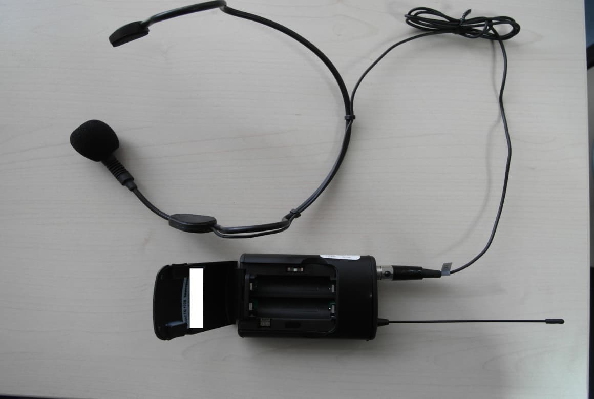
Click to zoom
Application Details
- Equipment Class
- TNT - Licensed Non-Broadcast Transmitter Worn on Body
- Date of Grant
- Feb 02, 2014
- Application Purpose
- Original Equipment
- Date of Application
- Feb 02, 2014
- Equipment Note
- Wireless microphone in VHF range
- Frequency Range
- 174.02600000 - 203.97400000
- Company
- Beyerdynamic
- Country
- United States
Documents & Files
Document Text
Text extracted from the exhibit documents filed with the FCC. Open a document above to read the original.
Users Manual
TG 100 Beltpack Set DRAHTLOSSYSTEM MIT TASCHENSENDER WIRELESS SYSTEM WITH BELTPACK TRANSMITTER SISTEMA WIRELESS CON TRASMETTITORE TASCABILE Bedienungsanleitung Operating Instructions Istruzioni per l’uso TG100_B_DE-EN-IT 12.12.2013 10:04 Uhr Seite 1 TG100_B_DE-EN-IT 12.12.2013 10:04 Uhr Seite 2 deutsch TG 100 – Inhalt 3 1. Sicherheitsinformationen . . . . . . . . . . . . . . . . . . . . . . . . . . . . . . . . . . Seite4 1.1Taschensender TG 100B . . . . . . . . . . . . . . . . . . . . . . . . . . . . . . Seite5 1.2NiMH-Akkus, Batterien . . . . . . . . . . . . . . . . . . . . . . . . . . . . . . . Seite6 1.3Entsorgung. . . . . . . . . . . . . . . . . . . . . . . . . . . . . . . . . . . . . . . . Seite6 2. Diversityempfänger TG 100R . . . . . . . . . . . . . . . . . . . . . . . . . . . . . . . Seite7 2.1Bedien- und Kontrollelemente . . . . . . . . . . . . . . . . . . . . . . . . . . Seite7 2.2Inbetriebnahme des Empfängers . . . . . . . . . . . . . . . . . . . . . . . . Seite9 3. Taschensender TG 100B. . . . . . . . . . . . . . . . . . . . . . . . . . . . . . . . . . . Seite 10 3.1Bedien- und Kontrollelemente . . . . . . . . . . . . . . . . . . . . . . . . . . Seite 10 3.2Inbetriebnahme des Taschensenders. . . . . . . . . . . . . . . . . . . . . . Seite 11 3.3Hinweise für den störungsfreien Betrieb . . . . . . . . . . . . . . . . . . . Seite 12 4. Problemlösung. . . . . . . . . . . . . . . . . . . . . . . . . . . . . . . . . . . . . . . . . . Seite 13 5. Ausführungen . . . . . . . . . . . . . . . . . . . . . . . . . . . . . . . . . . . . . . . . . . Seite 14 6. Zubehör . . . . . . . . . . . . . . . . . . . . . . . . . . . . . . . . . . . . . . . . . . . . . . Seite 14 7. Technische Daten. . . . . . . . . . . . . . . . . . . . . . . . . . . . . . . . . . . . . . . . Seite 15 8. Service . . . . . . . . . . . . . . . . . . . . . . . . . . . . . . . . . . . . . . . . . . . . . . . Seite 16 9. Zulassung und Anmeldepflicht . . . . . . . . . . . . . . . . . . . . . . . . . . . . . . Seite 16 TG100_B_DE-EN-IT 12.12.2013 10:04 Uhr Seite 3 TG 100 – Sicherheit 4 Sie haben sich für das Drahtlossystem TG 100 von beyerdynamic entschieden. Vielen Dank für Ihr Ver- trauen. Nehmen Sie sich bitte einige Minuten Zeit und lesen Sie diese Bedienungsanleitung vor Inbetrieb- nahme aufmerksam durch. Das System TG 100 arbeitet mit 8 einstellbaren Frequenzen im VHF-Frequenzbereich und ist in zwei Set- Varianten und verschiedenen Frequenzbereichen erhältlich: 1. Diversityempfänger und Handsender 2. Diversityempfänger und Taschensender inklusive Headset 1. Sicherheitsinformationen 1. Bitte lesen Sie diese Anweisungen. 2. Bitte bewahren Sie diese Anweisungen auf. 3. Bitte beachten Sie alle Warnhinweise. 4. Folgen Sie allen Anweisungen. 5. Verwenden Sie dieses Gerät nicht in der Nähe von Wasser. 6. Reinigen Sie das Gerät nur mit einem trockenen Tuch. 7. Montieren Sie das Gerät nicht neben Hitzequellen wie Heizkörpern, Wärmespeichern, Öfen oder anderen Geräten (auch Leistungsverstärkern), die Hitze abstrahlen. 8. Nehmen Sie keine Veränderungen am Netzstecker dieses Gerätes vor. 9. Sichern Sie das Netzkabel gegen Einquetschen oder Abknicken, insbesondere am Gerät selbst sowie an dessen Netzstecker. 10. Verwenden Sie nur das vom Hersteller benannte Zubehör für dieses Gerät. 11. Trennen Sie das Gerät vom Stromnetz, wenn ein Gewitter aufkommt oder wenn Sie es voraus- sichtlich für längere Zeit nicht verwenden werden. 12. Alle Wartungsarbeiten müssen von hierfür qualifizierten Servicemitarbeitern durchgeführt wer- den. Eine Wartung ist erforderlich, wenn das Gerät selbst oder dessen Netzkabel beschädigt wurde, Flüssigkeiten oder Gegenstände in das Gerät gelangt sind, das Gerät Regen oder starker Feuchtigkeit ausgesetzt wurde, das Gerät nicht ordnungsgemäß arbeitet oder es heruntergefallen ist. Haftungsausschluss • Die Firma beyerdynamic GmbH & Co. KG übernimmt keine Haftung für Schäden am Produkt oder Verletzungen von Personen aufgrund unachtsamer, unsachgemäßer, falscher oder nicht dem vom Hersteller angegebenen Zweck entsprechender Verwendung des Produkts. Standort • Das Gerät muss so aufgestellt werden, dass der Netzanschluss, Steckernetzteil und alle Anschlüsse auf der Rückseite des Gerätes leicht zugänglich sind. • Wenn Sie das Gerät an einen anderen Ort transportieren, achten Sie darauf, dass es ausreichend gesichert ist und niemand durch ein eventuelles Herunterfallen oder Stoßen am Gerät verletzt wer- den kann. Brandschutz • Stellen Sie niemals offene Brandquellen (z.B. Kerzen) auf das Gerät. Feuchtigkeit / Wärmequellen • Setzen Sie das Gerät niemals Regen oder hoher Feuchtigkeit aus. Installieren Sie es daher nicht in unmittelbarer Nähe von Swimming Pools, Duschanlagen, feuchten Kellerräumen oder sonstigen Bereichen mit außergewöhnlich hoher Luftfeuchtigkeit. • Stellen Sie niemals mit Flüssigkeiten gefüllte Gegenstände (z.B. Vasen oder Trinkgläser) auf das Gerät. Flüssigkeiten in den Geräten können einen Kurzschluss verursachen. TG100_B_DE-EN-IT 12.12.2013 10:04 Uhr Seite 4 TG 100 – Sicherheit 5 deutsch • Installieren und betreiben Sie das Gerät auch niemals in unmittelbarer Nähe von Heizkörpern, Beleuchtungsanlagen oder anderen wärmeerzeugenden Geräten. Anschluss • Verlegen Sie alle Kabel stets so, dass sie nicht durch scharfe Gegenstände geknickt oder gar durch- getrennt werden können. • Verlegen Sie alle Anschlusskabel so, dass niemand darüber stolpern und sich verletzen kann. • Schalten Sie bei allen Arbeiten an den Ein- und Ausgängen die Stromzufuhr aus. • Überprüfen Sie, ob die Anschlusswerte mit der vorhandenen Netzstromversorgung über einstimmen. Bei Anschluss des Systems an die falsche Stromversorgung können ernsthafte Schäden entstehen. Eine falsche Netzspannung kann das Gerät und Steckernetzteil beschädigen oder einen elektri- schen Schlag verursachen. • Beachten Sie, dass für verschiedene Netzspannungen entsprechende Steckernetzteile erforderlich sind. Siehe hierzu folgende Tabelle: • Wenn durch das Gerät…
Text truncated - open the document above for the full version.
Cover Letter(s)
CONFIDENTIALITY REQUEST for Certification Service in USA Federal Communication Commission Equipment Authorization Division, Application Processing Branch 7435 Oakland Mills Road Columbia, MD 21048 10.1.2014 TO WHOM IT MAY CONCERN Pursuant to Paragraphs §0.457 and 0.459 of the Commission’s Rules (47 C.F.R.) and Section §552(b)(4) of the Freedom of Information Act, we requests confidentiality for the following products: FCC ID Model name OSDTG100B TG 100B For the product stated above, we request permanent confidentiality for exhibits which contain Operational Description, Block Diagram, Schematics, Parts Lists or Tune Up Information. The above exhibits contain our trade secrets and proprietary information that could be of benefit to our competitors. If you have any questions, please feel free to contact me at the address shown below. Sincerely, Name: Ulrich Roth, Director of R&D Company: beyerdynamic GmbH & Co. KG Address: Theresienstrasse 8, 74072 Heilbronn, Germany Phone: +49 7131 617 155 Fax: +49 7131 617 224 Email: [email protected]
External Photos
Test report no.: 1-5822_13-01-06_AnnexA 2014-01-23 Page 1 of 5 Annex A This test report annex is electronically signed and valid without handwriting signature. For verification of the electronic signatures, the public keys can be requested at the testing laboratory. Test report annex authorised: David Lang Testing Manager Test report no.: 1-5822_13-01-06_AnnexA 2014-01-23 Page 2 of 5 External photos of the EUT Photo documentation: Photo 1: Photo 2: Test report no.: 1-5822_13-01-06_AnnexA 2014-01-23 Page 3 of 5 Photo 3: Photo 4: Test report no.: 1-5822_13-01-06_AnnexA 2014-01-23 Page 4 of 5 Photo 5: Test report no.: 1-5822_13-01-06_AnnexA 2014-01-23 Page 5 of 5 Document history Version Applied changes Date of release Initial release 2014-01-23
ID Label/Location Info
a a a a a b b c d d d c -Fertigungsdatum als FD Code nach Bosch-Norm N41A A4 -manufacuring date as FD code from Bosch standard N41 A A4 -Seriennummer fortlaufend Serienstart bei 01001 -serially numbered start with 01001 -Frequenzbereichangabe -frequency range -Produkt-Artnr. -item code 2013 DIN ISO 2768 mH 174 - 184 MHz Frequenzbereich / frequency rangeProdukt-Artnr./product No. 638390 Werkstoff / material Ausf. 03.05. Aufkleber/sticker dimensions: 41,5mm x 15,5mm corners: R0,5mm colour: aluminium colored -flat A B 638404194 - 204 MHz Bäurer C 638412213 - 223 MHz 03.05.Bäurer Ausführung/version C Ausführung/version A, B 1 - -- Ausg. 5 2x 22.01.14Bä 4 1x 04.06.13Sch 3 1x 24.05.13Bä 2 4x 21.05.13Bä F E D C B A 1234 Diese technische Unterlage ist ausschliesslich unser Eigentum. Ohne unsere vorherige Zustimmung darfsie weder vervielfältigt noch Dritten zugänglich gemacht werden. Wir behalten uns alle Rechte vor, auch für den Fall der Patentierung oder Gebrauchsmustereintragung. Änderungen von Massen oder Abweich-ungen von freigegebenen Mustern nur mit unserer Zustimmung. beyerdynamic )))) GmbH & Co. KG Ersatz für: Stück- gewicht: Massstab Blattformat Freimasstoleranz Passmasse in μm Solid Works H-SL-Bezeichnung NameTag Bearb. Gepr. 2:1 DIN A4 BN 35- 829 Typenschild / label
Internal Photos
Test report no.: 1-5822_13-01-06_AnnexB 2014-01-23 Page 1 of 5 Annex B This test report annex is electronically signed and valid without handwriting signature. For verification of the electronic signatures, the public keys can be requested at the testing laboratory. Test report annex authorised: David Lang Testing Manager Test report no.: 1-5822_13-01-06_AnnexB 2014-01-23 Page 2 of 5 Internal photos of the EUT Photo documentation: Photo 1: Photo 2: Test report no.: 1-5822_13-01-06_AnnexB 2014-01-23 Page 3 of 5 Photo 3: Photo 4: Test report no.: 1-5822_13-01-06_AnnexB 2014-01-23 Page 4 of 5 Photo 5: Photo 6: Test report no.: 1-5822_13-01-06_AnnexB 2014-01-23 Page 5 of 5 Document history Version Applied changes Date of release Initial release 2014-01-23
RF Exposure Info
Declaration regarding RF Exposure Federal Communication Commission Equipment Authorization Division, Application Processing Branch 7435 Oakland Mills Road Columbia, MD 21048 January 22, 2014 TO WHOM IT MAY CONCERN RF Exposure issue for any portable devices subject to 2.1093 routine evaluations regarding the following product: FCC ID Number Title/Model OSDTG100B TG 100B IC ID Title/Model 3628A-TG100B TG 100B SAR exemption: This device has been excluded from SAR testing based on source-based time-averaged conducted output power and KDB 447498 D01 section 4.3.1 1). This document serves as the RF exposure exhibit in the FCC Form 731 application in lieu of a SAR report. Operational Description: The TG 100B is a portable wireless Microphone System using FM modulation to transmit audio. RF Exposure Conditions: The device is intended for use in the portable exposure condition and the General Population / Uncontrolled RF exposure environment. RF Output Power: Tx frequency range: 174.025 – 203.975 MHz Test separation distance: 5mm Maximum Output Power including Tune-Up tolerance: 12.00 dBm+- 1dB (19.95 mW) [(max. power of channel, including tune-up tolerance, mW)/(min. test separation distance, mm)] · [√f (GHz)] ≤ 3.0/7.5 respectively • f(GHz) is the RF channel transmit frequency in GHz • Power and distance are rounded to the nearest mW and mm before calculation 25 • The result is rounded to one decimal place for comparison 19.95 ܹ݉ ݉݉5 √ 0.204 ܴܣܵ ݕݐ݅݉݁ݎݐݔ݁ ݃10 ݎ݂ ൌ1.807.5 The device is excluded from SAR testing.
Test Report
2014-01-28 Page 1 of 30 TEST REPORT Test report no.: 1-5822/13-01-06 Testing laboratory Applicant CETECOM ICT Services GmbH Untertuerkheimer Strasse 6 – 10 66117 Saarbruecken / Germany Phone: + 49 681 5 98 - 0 Fax: + 49 681 5 98 - 9075 Internet: http://www.cetecom.com e-mail: [email protected] Accredited Testing Laboratory: The testing laboratory (area of testing) is accredited according to DIN EN ISO/IEC 17025 (2005) by the Deutsche Akkreditierungsstelle GmbH (DAkkS) The accreditation is valid for the scope of testing procedures as stated in the accreditation certificate with the registration number: D-PL-12076-01-01 Area of Testing: Radio Communications & EMC (RCE) beyerdynamic GmbH & Co. KG Theresienstraße 8 74072 Heilbronn / GERMANY Phone: +49 7131 617-0 Fax: +49 7131 617-215 Contact: Ulrich Roth e-mail: [email protected] Phone: +49 7131 617-155 Manufacturer beyerdynamic GmbH & Co. KG Theresienstraße 8 74072 Heilbronn / GERMANY Test standard/s 47 CFR Part 74 Title 47 of the Code of Federal Regulations; Chapter I Part 74 - Experimental radio, auxiliary. special broadcast and other program distribution services RSS – 123 Issue 2 Spectrum Management and Telecommunications Policy - Radio Standards Specification Low Power Licensed Radiocommunication Devices For further applied test standards please refer to section 3 of this test report. Test Item Kind of test item: Wireless Microphone System Model name: TG 100B FCC ID: 3628A-TG100B IC: OSDTG100B Frequency: 174-184 MHz, 194-204 MHz Technology tested: Modulated carrier Antenna: Integrated antenna Power supply: +3.0V DC by Battery Temperature range: -10°C to +55°C This test report is electronically signed and valid without handwriting signature. For verification of the electronic signatures, the public keys can be requested at the testing laboratory. Test report authorised: Test performed: Michael Berg David Lang Senior Testing Manager Testing Manager Test report no.: 1-5822/13-01-06 2014-01-28 Page 2 of 30 1 Table of contents 1 Table of contents ............................................................................................................................................ 2 2 General information ....................................................................................................................................... 3 2.1 Notes and disclaimer .......................................................................................................................... 3 2.2 Application details ............................................................................................................................... 3 3 Test standard/s ............................................................................................................................................... 3 4 Test environment ............................................................................................................................................ 4 5 Test item .......................................................................................................................................................... 4 5.1 Additional information ........................................................................................................................ 4 6 Test laboratories sub-contracted ................................................................................................................. 4 7 Description of the test setup ......................................................................................................................... 5 7.1 Radiated measurements chamber C ................................................................................................. 5 7.2 Conducted measurements ................................................................................................................. 6 8 Summary of measurement results ............................................................................................................... 7 8.1 RSP100 test report cover sheet / performance test data ................................................................ 8 9 Measurement results ...................................................................................................................................... 9 9.1 Output power (radiated) ...................................................................................................................... 9 9.2 Frequency stability ............................................................................................................................ 10 9.2.1 Frequency error vs. temperature .............................................................................................. 10 9.2.2 Frequency error vs. voltage ...................................................................................................... 12 9.3 Modulation characteristics ............................................................................................................... 14 9.4 Occupied bandwidth ......................................................................................................................... 15 9.5 Unwanted radiation (spectrum mask) ............................................................................................. 18 9.6 Spurious emissions radiated < 30 MHz ........................................................................................... 21 9.7 Field strength of spurious radiation. ............................................................................................... 24 10 Test equipment and ancillaries used for tests ................................................................................... 27 11 Observations ......................................................................................................................................... 28 Annex A Document history ..................................................................................................…
Text truncated - open the document above for the full version.
Test Setup Photos
1-5822 Test report no.: 1-5822_13-01-06_AnnexC 2014-01-23 Page 1 of 4 Annex C This test report annex is electronically signed and valid without handwriting signature. For verification of the electronic signatures, the public keys can be requested at the testing laboratory. Test report annex authorised: David Lang Testing Manager Test report no.: 1-5822_13-01-06_AnnexC 2014-01-23 Page 2 of 4 Test setup photos Photo documentation: Photo 1: Photo 2: Test report no.: 1-5822_13-01-06_AnnexC 2014-01-23 Page 3 of 4 Photo 3: Photo 4: Test report no.: 1-5822_13-01-06_AnnexC 2014-01-23 Page 4 of 4 Document history Version Applied changes Date of release Initial release 2014-01-23
Contact Information
Applicant
Ulrich Roth(Director of R&D)
Test Firm
cetecom advanced GmbHGerald Schmidt
Technical Specifications
| # | Rule Parts | Frequency Range | Power Output | Emission | Tolerance |
|---|---|---|---|---|---|
| 1 | 74 | 174.026 MHz - 203.974 MHz | 2.00 mW | 115KF3E | 15.0000000000 ppm |
Other Applications from Beyerdynamic

OSDMMX230WL
Jan 05, 2026Wireless ANC Gaming Headset
Equipment Class
DSS - Part 15 Spread Spectrum Transmitter
OSDMMX230DLL
Dec 31, 2025Dongle
Equipment Class
DTS - Digital Transmission System
OSDAVENTHO200
Sep 29, 2025Wireless Over-Ear Headphones
Equipment Class
DTS - Digital Transmission SystemOSDAVENTHO300
Sep 18, 2024OVER-EAR WIRELESS HEADPHONES
Equipment Class
DTS - Digital Transmission SystemOSDAMIRON300
Sep 03, 2024True Wireless Earphones
Equipment Class
DTS - Digital Transmission System