OSF-MCP3020Bluetooth Speakerphone
Spracht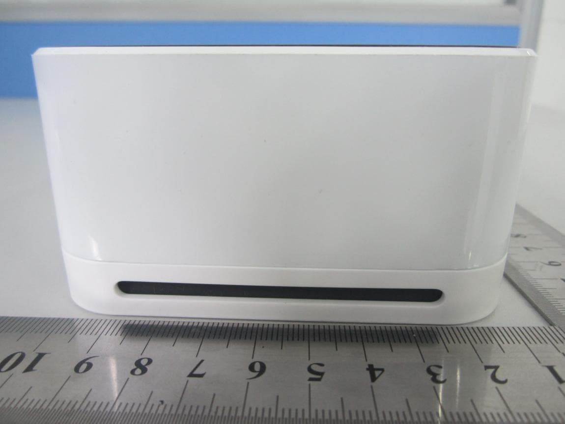
Click to zoom
Application Details
- Equipment Class
- DSS - Part 15 Spread Spectrum Transmitter
- Date of Grant
- Jan 01, 2014
- Application Purpose
- Original Equipment
- Date of Application
- Jan 01, 2014
- Equipment Note
- Bluetooth Speakerphone
- Frequency Range
- 2402.00000000 - 2480.00000000
- Company
- Spracht
- Country
- United States
Documents & Files
Document Text
Text extracted from the exhibit documents filed with the FCC. Open a document above to read the original.
Users Manual
MCP-3020 User Manual This equipment can be used in member states of the European Union once the corresponding administrative licence is obtained. WARNING:TO PREVENT FIRE OR ELECTRICAL SHOCK HAZARD, DO NOT EXPOSE THIS PROCUCT TO RAIN OR MOISTURE THE LIGHTING FLASH AND ARROW HEAD WITHIN THE TRIANGLE IS A WARNING SIGN ALERTING YOU OF “DANGEROUS VOLTAGE”INSINDE THE PRODUCT. CAUTION: TO REDUCE THE RISK OF ELECTRICAL SHOCK, DO NOT REMOVE COVER (OR BACK). NO USER SERVICEABLE PARTS INSIDE. REFER SERVICING TO QUALIFIED SERVICE PERSONNEL. THE EXCLAMATION WITHIN THE TRIANGLE IS WARNING SIGN ALERTING YOU OF IMPORTANT INSTRUCTIONS ACCOMPANYING THE PRODUCT. SEE MARKING ON BOTTOM / BACK OF PRODUCT Correct Disposal of this product This marking indicates that this product should not be disposed with other household wastes throughout the EU. To prevent possible harm to the environment or human health from uncontrolled waste disposal, recycle it responsibly to promote the sustainable reuse of material resources. To return your used device, please use the return and collection systems or contact the retailer where the product was purchased. They can take this product for environmental safe recycling. DESCRIPTION OF THE DEVICE : Volume + : Volume - : Mute : Talk On/ Off : Power/ Pairing Mode :LED Indicator : 3.5 mm input : Micro USB Charging Port : NFC antenna area CAUTION The adapter shall be installed near the equipment and shall be easily accessible. This charger is for indoor use only. CAUTION RISK OF EXPLOSION IF BATTERY IS REPLACED BY AN INCORRECT TYPE. DISPOSE OF USED BATTERIES ACCORDING TO THE INSTRUCTIONS. Hereby, Giant Telecom Ltd. declares that this device is in compliance with the essential requirements and other relevant provisions of Directive 1999/5/EC. The operating temperature range is 0°C to +40°C. FCC Information This device complies with Part 15 of the FCC Rules and with RSS-210 of Industry Canada. Operation is subject to the following two conditions: (1) This device may not cause harmful interference, and (2) this device must accept any interference received, including interference that may cause undesired operation. NOTE: The manufacturer is not responsible for any radio or TV interference caused by unauthorized modifications or changes to this equipment. Such modifications or changes could void the user’s authority to operate the equipment. The output power of this device is so low than the SAR test is not required. Le présent appareil est conforme aux CNR d'Industrie Canada applicables aux appareils radio exempts de licence. L'exploitation est autorisée aux deux conditions suivantes : (1) l'appareil ne doit pas produire de brouillage, et (2) l'utilisateur de l'appareil doit accepter tout brouillage radioélectrique subi, même si le brouillage est susceptible d'en compromettre le fonctionnement. This Class B digital apparatus complies with Canadian ICES-003. Cet appareil numérique de la classe B est conforme à la norme NMB-003 du Canada. Charging the Unit 1. Connect the micro USB plug to the micro USB charging port on the unit. 2. Connect the standard USB plug end of the cable to a power USB port on a computer or other USB charging device. 3. A red light will be on while the unit is charging and turn off when unit is fully charged. Note: 1. When the battery is low, the red LED will flash. 2. Suggest turning off the unit while charging, it can save more time than charging while powering on. 3. Charging the battery fully is normally about 5 hours via the standard PC USB socket. Power on/off your device The [Power on/off] button has 3 selections: To left: Power off your device. To middle: Power on your device. The Bluetooth Speaker will connect with the latest paired device. To right: Enter pairing mode. Pairing Your Device 1. Place the [Power on/off] button to the right, the unit will enter the pairing mode, the blue and red LED on the unit will flash alternately. 2. Turn your mobile’s Bluetooth function, and set it to the paring mode. 3. Set the mobile to search for the Bluetooth devices within 1 meter range and select ‘SP101-xxx’ from the list. 4. If pairing was successful, the blue LED will flash at a 5s interval. If battery is low, red LED will flash at a 5s interval instead of the blue LED. 5. If pairing fails, please repeat the process. Note: In pairing mode, the Bluetooth Speaker will enter sleep mode if no device paired successfully after 4 minutes. You must turn off and on the Bluetooth Speaker. Pairing Your Device via NFC 1. Turn on the NFC function of your mobile phone. 2. Place the [Power on/off] button to the right, the unit will enter the pairing mode, the blue and red LED on the unit will flash alternately. 3. Place your mobile phone to the indicator of. 4. Follow your mobile’s indication to complete the pairing process. Note: 1. The Bluetooth speaker just remembers the latest paired device. Answering a call When there is an incoming call, you will hear ringing through the Bluetooth speaker (some model may not support), and the will flash. Press to accept the call or answer the call via your mobile handset in the normal way. Reject a call When there is an incoming call, you will hear ringing through the Bluetooth speaker(some model may not support). Press to reject the call. Ending a call Press to end the call or end the call via your mobile handset in the normal way. Adjusting the Volume Press or to you desired volume level. Mute function During a call, you can press to mute the Microphone of Bluetooth Speaker, and the will be on in muting mode. Press again to return to the normal. LED indicator Music playback 1) Connecting to a Bluetooth A2DP cell phone or a Bluetooth transmitter. a) Make sure your cell phone or Bluetooth transmitter has already established an A2DP connection with the SP101. b) You can listen to your music from the SP101 while using your Bluetooth cell phone or other Bluetooth music device for playback. c) Adjust the volume: Short press button and button …
Text truncated - open the document above for the full version.
Cover Letter(s)
Date: December 3,2013 To: Federal Communications Commission, Authorization & Evaluation Division, 7435 Oakland Mills Road, Columbia, MD 21046 To Whom It May Concern: The Spracht , the undersigned, hereby authorizes Mrs. Ivy Zhu from Shenzhen Morlab Communications Technology Co., Ltd., to act on the behalf of the Spracht solely in matters relating to the application for an FCC equipment authorization for FCC ID OSF-MCP3020 including the signing of documents in connection with this Application. Necessary acts carried out by Shenzhen Morlab Communications Technology Co., Ltd. on our behalf in connection with the Application shall have the same effect as acts of the Spracht. The Spracht also hereby certify that no party to this application is subject to a denial of benefits, including FCC benefits, pursuant to Section 5301 of the Anti-Drug Abuse Act of 1988, 21 U.S.C. 853(a). Thank you for your attention to this matter. Yours Sincerely, Richard Slevin CEO
Cover Letter(s)
Date: December 3, 2013 To: Federal Communications Commission, Authorization & Evaluation Division, 7435 Oakland Mills Road, Columbia, MD 21046 Re: Spracht FCC ID: OSF-MCP3020 FCC Part 15C Certification Confidentiality Request Gentlemen: This letter is to comply with 47 CFR 0.457 and 0.459 pertaining to confidentiality material. Spracht requests that the following documents regarding this submission for FCC ID: OSF-MCP3020 be kept confidential: Exhibit Type File Name Block Diagram Block Diagram.pdf Schematics Operational Description Operational description.pdf Part list BOM.pdf Those documents contain detailed system and equipment description and related information about the product which OSF-MCP3020 considers to be confidential proprietary, a custom design and, otherwise, not releasable to the general public. Since this design is a basis form which future technological products will evolve, OSF-MCP3020 considers this information would be of benefit to its competitors, and that the disclosure of the information in these documents would give competitors an unfair advantage in the market. Richard Slevin CEO Schematics.pdf
External Photos
External Photos 1. EUT front view 2. EUT rear view 3. EUT left side view 4. EUT right side view 5. EUT top view 6. EUT bottom view
ID Label/Location Info
Giant Telecom Limited Customer : ODI Model : Conference Mate MCP-3020 & MCP-3022 Description : FCC Label and Product Rating Label P/N : KEM-PK34104-XX (see below remarks) Size : 44.5mm(w) x 16.5mm(h) Color : Black on White Artpaper Label Rev. : R05 Date : Nov 29 , 2013 Model : Conference Mate MCP-3022 Description : FCC Label P/N : KEM-PK34104-03 Model : Conference Mate MCP-3022 Description : Product Rating Label P/N : KEM-PK34104-01 Model : Conference Mate MCP-3020 Description : FCC Label P/N : KEM-PK34104-02 Model : Conference Mate MCP-3020 Description : Product Rating Label P/N : KEM-PK34104 This device complies with part 15 of the FCC Rules. Operation is subject to the following two conditions: (1) This device may not cause harmful interference, and (2) this device must accept any interference received, including interference that may cause undesired operation. This device complies with part 15 of the FCC Rules. Operation is subject to the following two conditions: (1) This device may not cause harmful interference, and (2) this device must accept any interference received, including interference that may cause undesired operation. 44.5 mm R1 x 3 16.5 mm 44.5 mm R1 x 3 16.5 mm MODEL NO.: MCP-3020 FCC ID: OSF-MCP3020 IC: 9091A-MCP3020 RATED: 5V --- 500mA Max MADE IN CHINA S/N : YMMXXXXXX MODEL NO.: MCP-3022 FCC ID: OSF-MCP3020 IC: 9091A-MCP3020 RATED: 5V --- 500mA Max MADE IN CHINA S/N : YMMXXXXXX
Internal Photos
Internal Photos 1. EUT uncover view 2. Mainboard front view 3. Mainboard rear view 4. BT chip view 5. BT antenna view
Test Report
Report No.:SZ13100083W02 Shenzhen Morlab Communications Technology Co., Ltd Phone: +86 (0) 755 36698555 Web site: http://www.morlab.cn/ Fax: +86 (0) 755 36698525 Email: [email protected] Page 2 of 91 TABLE OF CONTENTS 1. GENERAL INFORMATION ...................................................................................................................... 5 1.1. EUT DESCRIPTION .................................................................................................................................. 5 1.2. TEST STANDARDS AND RESULTS ............................................................................................................. 6 1.3. FACILITIES AND ACCREDITATIONS ............................................................................................................ 7 1.3.1. FACILITIES ....................................................................................................................................................... 7 1.3.2. TEST ENVIRONMENT CONDITIONS ................................................................................................................ 7 2. 47 CFR PART 15C REQUIREMENTS ..................................................................................................... 8 2.1. ANTENNA REQUIREMENT ......................................................................................................................... 8 2.1.1. APPLICABLE STANDARD ................................................................................................................................. 8 2.1.2. RESULT: COMPLIANT ...................................................................................................................................... 8 2.2. NUMBER OF HOPPING FREQUENCY ......................................................................................................... 8 2.2.1. REQUIREMENT ................................................................................................................................................ 8 2.2.2. TEST DESCRIPTION ........................................................................................................................................ 8 2.2.3. TEST PROCEDURE ......................................................................................................................................... 9 2.2.4. TEST RESULT .................................................................................................................................................. 9 2.3. PEAK OUTPUT POWER ........................................................................................................................... 13 2.3.1. REQUIREMENT .............................................................................................................................................. 13 2.3.2. TEST DESCRIPTION ...................................................................................................................................... 13 2.3.3. TEST RESULT ................................................................................................................................................ 13 2.3.3.1. GFSK MODE ............................................................................................................................................. 14 2.3.3.2. ∏/4-DQPSK MODE ................................................................................................................................. 14 2.3.3.3. 8-DPSK MODE ......................................................................................................................................... 14 2.4. 20DB BANDWIDTH .................................................................................................................................. 15 2.4.1. DEFINITION ................................................................................................................................................... 15 2.4.2. TEST DESCRIPTION ...................................................................................................................................... 15 2.4.3. TEST PROCEDURE ....................................................................................................................................... 15 2.4.4. TEST RESULT ................................................................................................................................................ 16 2.4.4.1. GFSK MODE ............................................................................................................................................. 16 2.4.4.2. ∏/4-DQPSK MODE ................................................................................................................................. 20 2.4.4.3. 8-DPSK MODE ......................................................................................................................................... 24 2.5. CARRIED FREQUENCY SEPARATION ....................................................................................................... 28 2.5.1. DEFINITION ................................................................................................................................................... 28 2.5.2. TEST DESCRIPTION ...................................................................................................................................... 28 2.5.3. TEST PROCEDURE ....................................................................................................................................... 28 2.5.4. TEST RESULT ................................................................................................................................................ 29 Report No.:SZ13100083W02 Shenzhen Morlab Communications Technology Co., Ltd Phone: +86 (0) 755 36698555 Web site: http://www.morlab.cn/ Fax: +86 (0) 755 36698525 Email: [email protected] Page 3 of 91 2.6. TIME OF OCCUPANCY (DWELL TIME) .......…
Text truncated - open the document above for the full version.
Test Setup Photos
Test Setup Photos 1. Conducted emission main’s port front view 2. Conducted emission main’s port side view 3. Radiated emission (9KHz-30MHz) 4. Radiated emission (30MHz-1GHz) 5. Radiated emission (above 1GHz) 6. Conducted emission antenna’s port
Contact Information
Applicant
Margarita Kovats(EVP)
Technical Contact
Shenzhen Morlab Communications Technology Co.,LtdIvy Zhu
[email protected]86-755-36698618
FL.3, Building A, FeiYang Science Park · ShenZhen, GuangDong Province · China
Test Firm
Shenzhen Morlab Communications Technology Co., LtdIvy zhu
Technical Specifications
| # | Rule Parts | Frequency Range | Power Output |
|---|---|---|---|
| 1 | 15C | 2.40 GHz - 2.48 GHz | 2.00 mW |
Other Applications from Spracht
OSF-IE-100
Apr 14, 2024In-Ear Hearing Protective Buds with Bluetooth Connectivity
Equipment Class
DSS - Part 15 Spread Spectrum TransmitterOSF-T-100BT
Apr 14, 2024Tactical Bluetooth Protective Ear Muffs
Equipment Class
DTS - Digital Transmission System
OSF-HS-OTE-Q
Nov 22, 2023Zum Over-The-Ear BT-Headset
Equipment Class
DTS - Digital Transmission System
OSF-BS669
Jul 31, 2012PORTABLE CONFERENCING + WIRELESS SPEAKER
Equipment Class
DSS - Part 15 Spread Spectrum Transmitter