OT8Z4KRZ4000 Remote Commander
MTH Electric Trains, Inc.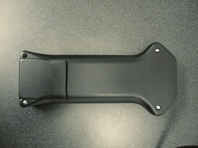
Click to zoom
Application Details
- Equipment Class
- DXX - Part 15 Low Power Communication Device Transmitter
- Date of Grant
- Feb 02, 2000
- Application Purpose
- Original Equipment
- Date of Application
- Dec 12, 1999
- Equipment Note
- Z4000 Remote Commander
- Frequency Range
- 916.40000000 - 916.60000000
- Company
- MTH Electric Trains, Inc.
- Country
- United States
Documents & Files
Document Text
Text extracted from the exhibit documents filed with the FCC. Open a document above to read the original.
Users Manual
C:\My Documents\FCC\Seitz\Z4K alt inst manual.doc Jason WenzelPage 112/13/99 MTH Electric Trains Z4K Remote Control System Instruction Manual C:\My Documents\FCC\Seitz\Z4K alt inst manual.doc Jason WenzelPage 212/13/99 Table of Contents Physical and Electrical Characteristics 3 Features4 Setup4 Operation5 Care and Maintenance6 A Few Words about 900Mhz7 Troubleshooting Guide7 C:\My Documents\FCC\Seitz\Z4K alt inst manual.doc Jason WenzelPage 312/13/99 PHYSICAL AND ELECTRICAL CHARACTERISTICS Z4K Remote Transmitter Batteries- • Requires 4 “AAA” alkaline Buttons- • Horn/Whistle – Activates horn or whistle • Bell/Select – Activates the bell and also selects a program (if in program mode) • Direction – Controls direction of movement for each locomotive • Program – Allows user to program certain functions on equipped locomotives • Boost – Momentarily increases train speed by increasing track voltage. Train returns to previous speed when released • Brake – Momentarily decreases train speed by decreasing track voltage. Train returns to previous speed when released • Emergency Stop – Drops voltage to zero on both tracks of selected Z4K when pressed • Throttle Thumb Wheel – Allows user to increase or decrease voltage supplied to the track(s) to speed up or slow down trains Switches- • Track Select switch – Allows user to select between which track to control, Track 1 or Track 2 • Transformer Select switch – Allows user to select between which Z4K to control Z4K 1, 2, or 3. You will need to purchase additional receivers if you wish to run more than one Z4K transformer. LCD- • One-line, two-digit display (Decimal point flashes when in Program mode) Transmitter- • 900Mhz technology Z4K Remote Receiver Connection- • RJ-11 connection to Z4K transformer Receiver- • 900Mhz technology C:\My Documents\FCC\Seitz\Z4K alt inst manual.doc Jason WenzelPage 412/13/99 FEATURES Transmitter- • Able to select between three different transformers and two tracks on each transformer for a total of 6 controllable tracks • 900Mhz technology allows the user to run trains from up to 30 feet away • LCD indicates commanded voltage on remotely controlled transformers • Emergency Stop button gives user the ability to instantly reduce track voltages to 0, thereby stopping the trains from a potentially harmful situation • Program button gives user the ability to remotely program the train (on Proto-Sound equipped locomotives). Also, to simplify programming the user can select which feature they want by scrolling with the throttle. Receiver- • User is able to place receiver out of sight because it operates in the 900Mhz range • Quick and easy connection to ANY Z4K transformer Expandability- • With the Z4K remote you can control up to three Z4K transformers (You will need a receiver for every transformer you wish to control) SETUP AND OPERATION OF Z4K REMOTE SETUP - This section describes how to setup your remote control unit so you can operate trains remotely. It also describes how to run multiple transformers with one remote To setup your remote control unit follow these steps: 1. Make sure the Z4K transformer’s power is OFF 2. Open the battery door on the transmitter and install 4 “AAA” alkaline batteries 3. Connect the RJ-11 jack on the receiver to the back of the Z4K transformer. There is no external power for the receiver, it receives it power from the transformer 4. Flip the Track select switch to 1 and flip the Z4K select switch to Z4K 1. This will allow you to take control of Track 1 on Z4K 1 5. Turn ON the power to the transformer 6. When the transformer powers up, watch the LED display. When the transformer resets it will display 40 00 in the volts window and 01 23 or 01 24 (depending upon the firmware version you have) in the amps window. Approximately 3 seconds later the volts window will go blank and the amps window will display PG PG. When this C:\My Documents\FCC\Seitz\Z4K alt inst manual.doc Jason WenzelPage 512/13/99 is displayed, press the Emergency Stop button and you should see -- -- in the volts window. Immediately following this, the transformer will display 0.0 0.0 in the volts window and RC RC in the amps window. You now have remote control of Track 1 on Z4K 1 7. Roll the throttle up and press the Direction button and you’re off and running 8. If you want to run track 2 on the same Z4K, flip the Track select switch to Track 2 and roll the throttle up and you’re now running on track 2. 9. If you have multiple Z4K transformers you can take control of them the same way as described above. The only thing you have to do is flip the Z4K select switch to Z4K 2 or 3 and repeat steps 4 and 5. Note- if you run more than one Z4K transformer it is possible that the receivers can be on the same channel. This will cause undesired operation on one of the Z4K transformers. Please see the Troubleshooting section on page 7 for more information regarding this. OPERATION – This section describes how to operate your remote control to perform such functions as sounding the bell, sounding the horn/whistle, changing direction, and programming your Proto-Sounds equipped engine. To operate your Z4K remote control, follow these steps: 1. To sound the horn or whistle, press and release the Horn/Whistle button. The longer you hold the button down the longer the horn or whistle will sound. The horn/whistle will stop when you release the button 2. To sound the bell, press and release the Bell/Select button. To turn the bell off, press and release the Bell/Select button again 3. To change the direction of the train, or to put it in neutral, press and release the Direction button 4. If you wish to slow the train or stop it momentarily, press and hold the Brake button. The train will slow to a stop. At the same time you will see the Z4K transformer indicated voltage drop to 5.0 volts. When you release the Brake button the train will speed up to the commanded voltage as displayed on the remote. At the same time you will see the Z4K transform…
Text truncated - open the document above for the full version.
Block Diagram
Transmitter block diagram 3.58 Mhz Processor SAW oscillator LPF TX Data 916.5 MHZ Slot Antenna Keypad LCD Display Power supply 4 AA size batterys
ID Label/Location Info
This device complies with part 15 of the FCC rules. Operation is subject to the following two conditions: (1) This device may not cause harmful interference and, (2) this device must accept any interference received including interference that may cause undesired operation. FCC ID: OT8Z4KR
Operational Description
Description of Operation The remote commander is a battery powered OOK data transmitter. The microcontroller controls all the functions - reading the keypad, displaying the operation modes, sending data to the RF transmitter. Pressing any pushbuttons cause the processor to send corresponding code sequence to RF transmitter. It is the SAW operated single frequency On-Off-Keyed oscillator. The operating frequency is 916.5 MHZ +/- 0.1 Mhz. Following the oscillator is the Low-Pass Filter, which supress high order harmonics of the transmitted signal. Antenna used in this design is a microstrip slot antenna and it is printed on the top side of the circuit board assembly. Remote commander is powered by 4 AA size batterys. In order to prolong battery life the processor goes to sleep mode if no buttons were pressed for a few minutes, and wakes up as soon as any pushbutton was pressed.
Schematics
3 Keystone 202's STOP Z1 Z2 TRK1 BOOST DIR BRAKE PROG BELLWST/HORN SLOT ANTENNA916.5MHZ Z4000REMOTE TRANSMITTERD Z4KREMTX B 11Thursday, August 26, 1999 Title SizeDocument NumberRev Date:Sheetof BP/574 DRIVE0 DRIVE1 DRIVE2 DRIVE3 READ1 READ2 READ3READ3 DRIVE0 DRIVE1 DRIVE2 DRIVE3 READ0READ0 PC0 PC0 PC3 PC1 PC1 PC0 PC7 PC2 PC4 PC5 PC5 PC7 PC6 PC1 PC4 PC5 PC[0..7] PC3 PC3 PC6 PC2 PC4 PC2 PC6 TXD VCC VCC VCC VCC VCC VCC R2 4.7K 1 2 U3 74HC574 2 3 4 5 6 7 8 9 11 1 19 18 17 16 15 14 13 12 20 10 D1 D2 D3 D4 D5 D6 D7 D8 CLK OC Q1 Q2 Q3 Q4 Q5 Q6 Q7 Q8 VCC GND Q3 MMBR901LT1 1 2 3 R3 22 12 R4 4.7K 1 2 L1 3.9NH 1 2 C6 4pF C3 1.5PF C1 33pF C5 33pF R9 330 1 2 C2 33pF S3 12 43 S4 12 43 S5 12 43 S6 12 43 S9 12 43 S8 12 43 S7 12 43 S10 12 43 S11 12 43 S12 12 43 SW1 ENCODER 1 3 2 OUT1 OUT2 COM U1 PIC16LC62B-04/SO 9 10 1 20 8 19 2 3 4 5 6 7 21 22 23 24 25 26 27 28 11 12 13 14 15 16 17 18 OSC1 OSC2 MCLR VDD VSS VSS RA0 RA1 RA2 RA3 RA4 RA5 RB0 RB1 RB2 RB3 RB4 RB5 RB6 RB7 RC0 RC1 RC2 RC3 RC4 RC5 RC6 RC7 X1 3.58Mhz RESON 1 2 3 MH1 NR 1 MH2 NR 1 MH3 NR 1 MH4 NR 1 FID1 NR 1 FID2 NR 1 J1 BATCON 1 J2 BATCON 1 D2B BAV99 13 D2A BAV99 32 + C8 10uF 6.3V 9 10 1 20 8 19 2 3 4 5 6 7 21 22 23 24 25 26 27 28 11 12 13 14 15 16 17 18 OSC1 OSC2 MCLR VDD VSS VSS RA0 RA1 RA2 RA3 RA4 RA5 RB0 RB1 RB2 RB3 RB4 RB5 RB6 RB7 RC0 RC1 RC2 RC3 RC4 RC5 RC6 RC7 C9 .1uF MH5 NR 1 MH6 NR 1 MH7 NR 1 MH8 NR 1 MH9 NR 1 MH10 NR 1 MH11 NR 1 MH12 NR 1 MH13 NR 1 MH14 NR 1 MH15 NR 1 MH16 NR 1 MH18 NR 1 MH19 NR 1 MH20 NR 1 MH21 NR 1 MH22 NR 1 MH23 NR 1 MH24 NR 1 R12100K 12 C4 0.5PFC11 4pF C7 1.5PF C14 .1uF SR1 RO2144A 1 3 2 4 TERM1 TERM2 NC NC L2 5.6NH 12 F1 NR 1 F2 NR 1 F3 NR 1 F4 NR 1 F5 NR 1 F6 NR 1 F7 NR 1 F8 NR 1 F9 NR 1 F10 NR 1 F17 NR 1 F16 NR 1 U2 LCD_ASI-010 14 13 4 3 2 15 16 10 9 8 7 6 11 12 5 1 18 17 A1 B1 C1 D1 E1 F1 G1 A2 B2 C2 D2 E2 F2 G2 DP COM COM NC R13 470 12 D3 MA3033 1 3 SH1 RF SHIELD 1 2 3 4 5 6
Test Report
Measurement/Technical Report MTH Electric Trains, Inc., Z4000 Remote Commander FCC ID: OT8Z4KR July 22, 1999 This report concerns (check one):Original Grant √__ Class II Change_____ Equipment Type: Intentional Radiator (FCC Part 15.249) Deferred grant requested per 47 CFR 0.457 (d)(1)(ii)?yes_____ no__X__ If yes, defer until:______N/A______ date Cardio Theater agrees to notify the Commission by:______N/A______ date of the intended date of announcement of the product so that the grant can be issued on that date. Transition Rules Request per 15.37:yes_____ no__X__ If no, assumed Part 15, Subpart B for unintentional radiators - new 47 CFR [10-1-92] provision. Report prepared by:Northwest EMC, Inc. 22975 NW Evergreen Parkway, Suite 400 Hillsboro, OR 97124 (503) 844-4066 fax: (503) 844-3826 Report No. SEIT0042.1 FCC ID: OT8Z4KR Northwest EMC, Inc.Report No. SEIT0042.1Page - 2 Table of Contents SectionDescriptionPage 1.0General Information3 1.1Product Description3 1.2Related Submittals/Grants4 1.3Tested System Details4 1.4Test Methodology5 1.5Test Facility5 2.0System Test Configuration6 2.1Justification6 2.2EUT Exercise Software6 2.3Special Accessories6 2.4Equipment Modifications6 Figure 2.1Configuration of Tested System7 3.0Radiated Emissions Data8 3.2Field Strength Calculations9 3.3Measurement Bandwidths9 4.0Measurement Equipment10 Appendix IMeasurement Procedures13 FCC ID: OT8Z4KR Northwest EMC, Inc.Report No. SEIT0042.1Page - 3 1.0 General Information 1.1 Product Description Manufactured By....................................................................................MTH Electric Trains, Inc. Address.........................................................................3820 M-139, St. Joseph, MI 49085-9605 Test Requested By:...........................................................Eduard Vaynberg – Seitz & Associates Model................................................................................................Z4000 Remote Commander FCC ID..........................................................................................................................OT8Z4KR Serial Number(s).....................................................................................................................N/A Date of Test..............................................................................................................July 22, 1999 Job Number................................................................................................................SEIT0042.1 The Equipment Under Test (EUT) is the MTH Electric Trains Z4000 Remote Commander Transmitter. Hardware Description: • Clocks/Oscillators Frequencies: 3.58 MHz, 916.5 MHz • Ports: Modular cable to connect Receiver to Train Power Supply • Antenna: Microstrip slot antenna, printed on top side of the circuit board assembly FCC ID: OT8Z4KR Northwest EMC, Inc.Report No. SEIT0042.1Page - 4 1.2 Related Submittals/Grants None. 1.3 Tested System Details EUT and Peripherals ItemFCC IDDescription and Serial No. EUTOT8Z4KRMTH Electric Trains, Z4000 Remote Commander , Low Power Transmitter Model 40-4001, Serial No. None. ReceiverMTH Electric Trains, Z4000 Remote Commander Receiver Model 40-4002, Serial No. None. Power SupplyN/A Cables: Item Description Power0.5 meters in length. Not shielded and no ferrite beads. Plastic connector. Connected from the EUT (Receiver) to the Power Supply. 1.4 Test Methodology Both conducted and radiated testing was performed according to the procedures in ANSI C63.4 (1992). Radiated testing was performed at an antenna to EUT distance of 3 meters. Please reference Appendix I for further detail on Test Methodology. FCC ID: OT8Z4KR Northwest EMC, Inc.Report No. SEIT0042.1Page - 5 1.5 Test Facility The Open Area Test Site and conducted measurement facility used to collect the radiated and conducted data is located at Northwest EMC, Inc. 120 South Elliott Road Newberg, OR 97132 (503) 537-0728 Fax: 537-0735 The Open Area Test Site, and conducted measurement facility used to collect this data is located at the address shown above. This site has been fully described in a report filed and accepted by the FCC. (31040/SIT)(1300B3). It is also recognized under the National Voluntary Laboratory Accreditation Program (NVLAP Lab Code: 200059-0) for satisfactory compliance with criteria established in Title 15, Part 285 Code of Federal Regulations. Northwest EMC, Inc., has been assessed and accredited by NEMKO (Norwegian testing and certification body) for European emissions and immunity testing. As a result of NEMKO's laboratory assessment, they will accept test results from Northwest EMC, Inc., for product certification (Authorization No. ELA 119). Northwest EMC, Inc. is recognized under the United States Department of Commerce, National Institute of Standards and Technology, National Voluntary Laboratory Accreditation Program (NVLAP) for satisfactory compliance with criteria established in Title 15, Part 285 Code of Federal Regulations. These criteria encompass the requirements of ISO/IEC Guide 25 and the relevant requirements of ISO 9002 (ANSI/ASQC Q92-1987) as suppliers of calibration or test results. NVLAP Lab Code: 200059-0. FCC ID: OT8Z4KR Northwest EMC, Inc.Report No. SEIT0042.1Page - 6 2.0 System Test Configuration 2.1 Justification The EUT was configured to simulate typical use. Cables were attached to each of the available I/O Ports. Where applicable, peripherals were attached to the I/O Cables. The mode of operation utilized for testing was selected in order to best simulate typical EUT use. 2.2 EUT Exercise Software Since there is no external data connection available, no external software can be used. 2.3 Special Accessories No special accessories are sold with the EUT. 2.4 Equipment Modifications No EMI suppression devices were added or modified. The EUT was tested as delivered. FCC ID: OT8Z4KR Northwest EMC, Inc.Report No. SEIT0042.1Page - 7 Figure 2.1: Configuration of Tested System A/B 1 Power Su…
Text truncated - open the document above for the full version.
Test Report
Comments: Frequency Meter ReadingDetector Antenna Factor Antenna PolarityPreamp GainCable LossTable Azimuth Antenna Height Adjusted LevelSpec. LimitMargin (MHz)(dBuV)(dB/m)(dB)(dB)(degrees)(meters)(dBuV/m)(dBuV/m)(dB) 916.46751.4QP28.3HDIP0.06.5210.01.086.294.0-7.8 916.46151.0PK28.3HDIP0.06.5210.01.085.894.0-8.2 916.47547.4QP28.3VDIP0.06.5150.01.682.294.0-11.8 916.45546.8PK28.3VDIP0.06.5150.01.681.694.0-12.4 72.45448.0QP7.1HBIC32.01.6180.02.524.740.0-15.3 72.46447.5QP7.1VBIC32.01.6100.01.024.240.0-15.9 53.20039.7QP10.7VBIC32.01.4100.01.319.840.0-20.2 188.62034.6QP17.0VBIC31.82.4100.02.022.243.5-21.3 916.43436.4AV28.3HDIP0.06.5210.01.071.294.0-22.8 916.48634.8AV28.3VDIP0.06.5150.01.669.694.0-24.4 53.20034.8QP10.7HBIC32.01.4120.02.214.940.0-25.1 188.62030.4QP17.0HBIC31.82.4150.02.018.043.5-25.5 516.00029.6QP18.1VLPA32.14.7100.02.020.346.0-25.7 516.00029.3QP18.1HLPA32.14.7100.02.020.046.0-26.0 394.00028.4QP16.0VLPA31.43.9100.02.016.946.0-29.1 394.00027.0QP16.0HLPA31.43.9100.03.015.546.0-30.5 279.86229.9QP13.8HLPA31.63.2100.01.515.346.0-30.7 279.86227.6QP13.8VLPA31.63.2100.02.013.046.0-33.0 APFAQEAAJABAADCALD Test Equipment Test System EUTTransmitter No Caps on back of transmitter. Receiver w/cable. Temperature (°C):% Humidity: 2140 Customer Reference Number:Software:Power: Manufacturer:Test Engineer:Job Site: SeitzJennifer HewittEL01 FCC Class B, Subpart C (3 Meter Limit) Northwest EMC, Inc., Radiated and Conducted Emissions Data Sheets EUT:Serial Number:Job Number:Date: Z4K Transmitter & ReceiverSEIT004207/22/99 0.0 10.0 20.0 30.0 40.0 50.0 60.0 70.0 80.0 101001000 Frequency (MHz) dBuV/meter Comments: Frequency Meter ReadingDetector Antenna Factor Antenna PolarityPreamp GainCable LossTable Azimuth Antenna Height Adjusted LevelSpec. LimitMargin (MHz)(dBuV)(dB/m)(dB)(dB)(degrees)(meters)(dBuV/m)(dBuV/m)(dB) 4582.30045.2PK34.9HHRN34.04.620.02.050.754.0-3.3 4582.30045.2PK34.9VHRN34.04.6250.01.050.754.0-3.3 3665.80045.9PK33.2VHRN34.14.360.01.049.354.0-4.7 4988.50042.6PK35.9VHRN34.04.8270.02.049.354.0-4.7 4988.50041.0PK35.9HHRN34.04.8250.02.047.754.0-6.3 3665.80044.2PK33.2HHRN34.14.320.01.047.654.0-6.4 1832.90050.3PK28.6HHRN35.13.1110.01.846.954.0-7.1 1832.90050.1PK28.6VHRN35.13.1330.01.046.754.0-7.3 2749.40044.2PK31.3HHRN34.53.8200.01.044.854.0-9.2 4582.30037.6AV34.9HHRN34.04.620.02.043.154.0-10.9 2749.40041.4PK31.3VHRN34.53.8300.01.042.054.0-12.0 4582.30035.5AV34.9VHRN34.04.6250.01.041.054.0-13.0 3665.80037.1AV33.2VHRN34.14.360.01.040.554.0-13.5 4988.50032.5AV35.9VHRN34.04.8270.02.039.254.0-14.8 1832.90041.2AV28.6HHRN35.13.1110.01.837.854.0-16.2 3665.80033.5AV33.2HHRN34.14.320.01.036.954.0-17.1 1832.90039.6AV28.6VHRN35.13.1330.01.036.254.0-17.8 4988.50029.2AV35.9HHRN34.04.8250.02.035.954.0-18.1 2749.40031.2AV31.3HHRN34.53.8200.01.031.854.0-22.2 2749.40028.7AV31.3VHRN34.53.8300.01.029.354.0-24.7 FCC Class B (3 Meter Limit) Northwest EMC, Inc., Radiated and Conducted Emissions Data Sheets EUT:Serial Number:Job Number:Date: Z4K Transmitter & ReceiverSEIT004207/22/99 Manufacturer:Test Engineer:Job Site: Seitz & AssociatesJennifer HewittEL01 Customer Reference Number:Software:Power: No Caps on back of transmitter. Receiver w/ cable. Temperature (°C):% Humidity: 2140 Test System EUTTransmitter Test Equipment APPAAMAHC 0.0 10.0 20.0 30.0 40.0 50.0 60.0 70.0 80.0 10002000300040005000600070008000900010000 Frequency (MHz) dBuV/meter
Test Report
Declaration of Conformity Responsible Party: MTH Electric Trains, Inc. Address:3820 M-139 St. Joseph, MI 49085-9605 Phone No:616-556-9560 Product Identification: Z4000 Remote Commander This device complies with Part 15.249 of the FCC Rules. Operation is subject to the following two conditions: (1) This device may not cause harmful interference, and (2) This device must accept any interference received, including interference that may cause undesired operation. Tested By: Northwest EMC, Inc. NVLAP Code: 200059-0 Dave Krebiehl, VP Research & Development Date Report No: SEIT0042
Contact Information
Applicant
Dave Krebiehl(Vice President of Research and Development)
616-556-9560Fax: 616-556-9562
Technical Contact
Northwest EMC, Inc.Gregory V Kiemel
[email protected](503)844-4066
22975 NW Evergreen Parkway · Hillsboro, Oregon · United States
Non-Technical Contact
Northwest EMC, Inc.Stephanie McCarson
[email protected](503)844-4066
Test Firm
Northwest EMC, Inc.Greg Kiemel
Technical Specifications
| # | Rule Parts | Frequency Range | Power Output |
|---|---|---|---|
| 1 | 15C | 916.4 MHz - 916.6 MHz | - |
Other Applications from MTH Electric Trains, Inc.
OT8RFMR
Apr 26, 2001Hand Held RF Module
Equipment Class
DSR - Part 15 Remote Control/Security Device Transceiver
OT8RFMT
Apr 26, 2001Base RF Module
Equipment Class
DSR - Part 15 Remote Control/Security Device Transceiver