OUC003MKeyless Operation Key (FOB)
NIDEC MOBILITY CORPORATION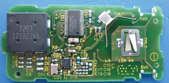
Click to zoom
Application Details
- Equipment Class
- DSC - Part 15 Security/Remote Control Transmitter
- Date of Grant
- Jan 15, 2014
- Application Purpose
- Original Equipment
- Date of Application
- Jan 15, 2014
- Equipment Note
- Keyless Operation Key (FOB)
- Frequency Range
- 315.00000000 - 315.00000000
- Company
- NIDEC MOBILITY CORPORATION
- Country
- Japan
Documents & Files
Document Text
Text extracted from the exhibit documents filed with the FCC. Open a document above to read the original.
Users Manual
WARNING - Changes or modifications not expressly approved by the party responsible for compliance could void the user’s authority to operate the equipment . Your Keyless Operation Key (FOB) operates on a radio frequency subject to Federal Communications Commission (FCC) Rules (For vehicle sold in U.S.A.) and Industry Canada Rules (For vehicles sold in Canada). This device complies with part 15 of FCC Rules and Industry Canada licence-exempt RSS standard(s).Operation is subject to the following two conditions: - This device may not cause harmful interference, and- This device must accept any interference, including interference that may cause undesired operation of this device. Since this device is always used with vehi cle, it is not sold to general end users separately. Therefore there is no user manual of this device by alone. The following information must be descri bed on the user manual of the vehicle; AVERTISSEMENT - Tout changement ou toute modification effectués par l’utilisateur et dont la conformité n’est pas expressément approvée par l’organisme responsablede sa conformité peut entraîner l’annulation de droitde cet utilisateur de se servir de l’équipment. Votre clé de fonctionnement sans clé (FOB) fonctionne sur unefréquence radio relevant de la réglementation établie par la Commission fédérale des communications (FCC) (pour les véhicules vendus aux États-Unis) et de la réglementation établiepar Industrie Canada (pour les véhicules vendus au Canada). Cetappareil est conforme à la section 15 du Réglement de la FCC et du CNR d'Industrie Canada applicable aux appareils radio exempts de licence. Son fonctionnement est soumis aux deux conditions suivantes : - Ce dispositif ne peut causer d’interférences.- Ce dispositif doit accepter toute interférences, y compris les interférences pouvant provoquer un fonctionnment indésirable de ce dispositif. Rev.C 2014/1/10 -4- - Function The functions of KOS are as below. 1. Keyless start function 1) Door entry function By pressing Request SW on DR/AS door,Trunk or ETG while bringing a FOB, KOS and FOB performs authentication by two-way communication and all doors are unlocked or locked. 2) Engine start function By pressing Engine Start SW while bringing a FOB, KOS and FOB performs authentication by two-way communication and engine start is permitted. 2. Keyless entry function All doors are locked by pressing Lock button on a FOB. Also, opposite behavior is performed by pressing Unlock button. Trunk(ETG) is opened by pressing Trunk(ETG) button. 3. Immobilizer function In case that FOB is out of battery (or low battery), the engine is started by inserting FOB (transponder) into FOB Box. Unauthorized engine start like stealing is prevented with two-way communication between KOS and FOB (transponder).
External Photos
Rev.B 2014/1/7 -12- - 8. Photographs (4 switches) Figure 8.1 Appearance (front view) Figure 8.2 Appearance (back view) Figure 8.3 Appearance (side view1) Figure 8.4 Appearance (side view2) Rev.B 2014/1/7 -13- - Figure 8.5 Appearance (side view3) Figure 8.6 Appearance (side view4) Figure 8.7 PCB assy (front view) Figure 8.8 PCB assy (back view)
ID Label/Location Info
1 ■GHR-M003 ラベル(マーキング)配置図
Internal Photos
4 switches Pattern Antenna
Test Report
Test report No. : 10116172H-A Page : 2 of 18 Issued date : January 7, 2014 FCC ID : OUC003M UL Japan, Inc. Head Office EMC Lab. 4383-326 Asama-cho, Ise-shi, Mie-ken 516-0021 JAPAN Telephone : +81 596 24 8999 Facsimile : +81 596 24 8124 REVISION HISTORY Original Test Report No.: 10116172H-A Revision Test report No. Date Page revisedContents - (Original) 10116172H-A January 7, 2014- - Test report No. : 10116172H-A Page : 3 of 18 Issued date : January 7, 2014 FCC ID : OUC003M UL Japan, Inc. Head Office EMC Lab. 4383-326 Asama-cho, Ise-shi, Mie-ken 516-0021 JAPAN Telephone : +81 596 24 8999 Facsimile : +81 596 24 8124 CONTENTS PAGE SECTION 1: Customer information ·············································································· 4 SECTION 2: Equipment under test (E.U.T.) ···································································· 4 SECTION 3: Test specification, procedures & results························································· 5 SECTION 4: Operation of E.U.T. during testing ······························································· 8 SECTION 5: Radiated emission (Electric Field Strength of Fundamental and Spurious Emission) 9 SECTION 6: Automatically deactivate ········································································· 10 SECTION 7: -20dB and 99% Occupied Bandwidth ························································· 10 APPENDIX 1: Data of EMI test ·················································································· 11 Automatically deactivate................................................................................................................... 11 Radiated Emission (Electric Field Strength of Fundamental and Spurious Emission) ..................... 12 -20dB and 99% Occupied Bandwidth ............................................................................................... 12 Duty Cycle ........................................................................................................................................ 14 APPENDIX 2: Test Instruments ················································································· 15 APPENDIX 3: Photographs of test setup ······································································· 16 Radiated emission ............................................................................................................................. 16 Worst case position ........................................................................................................................... 17 Test report No. : 10116172H-A Page : 4 of 18 Issued date : January 7, 2014 FCC ID : OUC003M UL Japan, Inc. Head Office EMC Lab. 4383-326 Asama-cho, Ise-shi, Mie-ken 516-0021 JAPAN Telephone : +81 596 24 8999 Facsimile : +81 596 24 8124 SECTION 1: Customer information Company Name : OMRON Automotive Electronics Co. Ltd. Address : 6368 NENJOZAKA OKUSA KOMAKI AICHI, 485-0802 JAPAN Telephone Number : +81-568-78-6159 Facsimile Number : +81-568-78-7659 Contact Person : Masashi Matsuda SECTION 2: Equipment under test (E.U.T.) 2.1 Identification of E.U.T. Type of Equipment : FOB (Keyless Operation Key) Model No. : GHR-M003 Serial No. : Refer to Clause 4.2 Receipt Date of Sample : November 28, 2013 Country of Mass-production : China Condition of EUT : Production prototype (Not for Sale: This sample is equivalent to mass-produced items.) Modification of EUT : No Modification by the test lab 2.2 Product Description Model No: GHR-M003 is the FOB (Keyless Operation Key) (hereafter referred to as FOB). - FOB is a component part of “Keyless start system” (hereinafter referred to as KOS). - FOB performs UHF transmission when its button is pressed and it receives LF from KOS. FOB has a transponder that performs mutual communication with KOS at IG ON (engine start). - KOS is a system to lock/unlock (door entry function) a door /trunk/ETG by pressing switch (for Lock/Unlock/Trunk/ETG) on each door with holding the registered FOB and start up an engine (engine starter function) without using a mechanical ignition key. These operation can be done without pulling FOB from a pocket or bag. General Specification Operating Voltage : DC 2.1V to 3.3V Battery : Lithium battery (CR2032) Operating Temperature : -20 deg. C to +60 deg. C Radio Specification [Transmitter] Radio Type : Transmitter Frequency of Operation : 315MHz Local clock frequency : 18.610MHz Modulation : FSK Method of Frequency Genenration : Crystal resonator [Receiver]* Radio Type : Receiver Frequency of Operation : 125kHz Clock frequency : 16MHz Modulation : ASK * Receiver part was tested according to FCC Part 15 Subpart B standard. Please see UL Japan, Inc. Test Report No. 10116172H-B. Test report No. : 10116172H-A Page : 5 of 18 Issued date : January 7, 2014 FCC ID : OUC003M UL Japan, Inc. Head Office EMC Lab. 4383-326 Asama-cho, Ise-shi, Mie-ken 516-0021 JAPAN Telephone : +81 596 24 8999 Facsimile : +81 596 24 8124 SECTION 3: Test specification, procedures & results 3.1 Test Specification Test Specification : FCC Part 15 Subpart C: 2013, final revised on September 30, 2013 and effective October 30, 2013 Title : FCC 47CFR Part15 Radio Frequency Device Subpart C Intentional Radiators Section 15.231 Periodic operation in the band 40.66 - 40.70MHz and above 70MHz 3.2 Procedures and results Item Test Procedure Specification Worst margin Results Remarks Conducted emission FCC: ANSI C63.4:2003 7. AC powerline conducted emission measurements FCC: Section 15.207 N/A N/A*1) - IC: RSS-Gen 7.2.4 IC: RSS-Gen 7.2.4 Automatically Deactivate FCC: ANSI C63.4:2003 13. Measurement of intentional radiators FCC: Section 15.231(a)(1) N/A Complied Radiated IC: - IC: RSS-210 A1.1.1 Electric Field Strength of Fundamental Emission FCC: ANSI C63.4:2003 13. Measurement of intentional radiators FCC: Section 15.231(b) 0.9dB 315.000MHz Horizontal PK with Duty factor Complied Radiated IC: RSS-Gen 4.8 IC: RSS-210 A1.1.2 Electric Field Strength of Spurious Emission…
Text truncated - open the document above for the full version.
Test Setup Photos
Test report No. : 10116172H-A Page : 16 of 18 Issued date : January 7, 2014 FCC ID : OUC003M UL Japan, Inc. Head Office EMC Lab. 4383-326 Asama-cho, Ise-shi, Mie-ken 516-0021 JAPAN Telephone : +81 596 24 8999 Facsimile : +81 596 24 8124 APPENDIX 3: Photographs of test setup Radiated emission Photo 1 Photo 2 Test report No. : 10116172H-A Page : 17 of 18 Issued date : January 7, 2014 FCC ID : OUC003M UL Japan, Inc. Head Office EMC Lab. 4383-326 Asama-cho, Ise-shi, Mie-ken 516-0021 JAPAN Telephone : +81 596 24 8999 Facsimile : +81 596 24 8124 Worst case position Below 1GHz Horizontal: X-axis/Vertical : Y-axis Above 1GHz Horizontal: X-axis/Vertical : Y-axis X-axis Y-axis Z-axis Test report No. : 10116172H-A Page : 18 of 18 Issued date : January 7, 2014 FCC ID : OUC003M UL Japan, Inc. Head Office EMC Lab. 4383-326 Asama-cho, Ise-shi, Mie-ken 516-0021 JAPAN Telephone : +81 596 24 8999 Facsimile : +81 596 24 8124 Worst case position Mechanical Key (Inserted) Mechanical Key (Not Inserted) worst case End of Report
Contact Information
Applicant
Shinya Takenouchi(Manager)
Technical Contact
UL Japan, Inc.Masanori Nishiyama
[email protected]81-596-24-8999
4383-326 Asama-cho, Ise-shi · Mie-ken · Japan
Test Firm
UL Japan, Inc. Head office EMC Lab.Tetsuya Hashimoto
Technical Specifications
| # | Rule Parts | Frequency Range | Power Output |
|---|---|---|---|
| 1 | 15.231 | 315 MHz - 315 MHz | - |
Other Applications from NIDEC MOBILITY CORPORATION
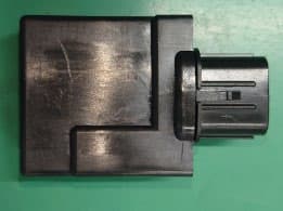
OUCTPMS1R
Jul 02, 2023TPMS ECU
Equipment Class
CYY - Communications Receiver used w/Pt 15 Transmitter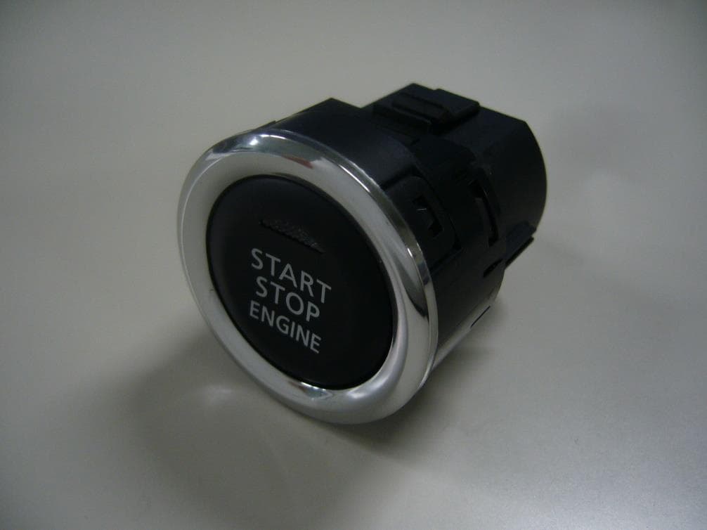
OUCR328E
Nov 29, 2020Transmitter of Keyless Entry System
Equipment Class
DCD - Part 15 Low Power Transmitter Below 1705 kHz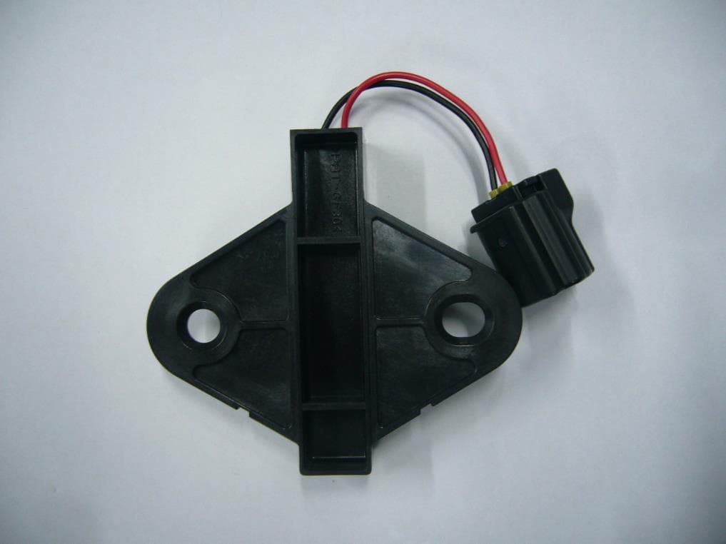
OUCR515E
Nov 29, 2020Transmitter of Keyless Entry System
Equipment Class
DCD - Part 15 Low Power Transmitter Below 1705 kHz
OUC744M-KEY-N
Sep 23, 2020Keyless Operation Key (FOB)
Equipment Class
DSC - Part 15 Security/Remote Control Transmitter
OUCGGM-M018
Aug 04, 2020ETACS
Equipment Class
CYY - Communications Receiver used w/Pt 15 Transmitter