OUC11545917Ignition Immobilizer Transmitter
NIDEC MOBILITY CORPORATION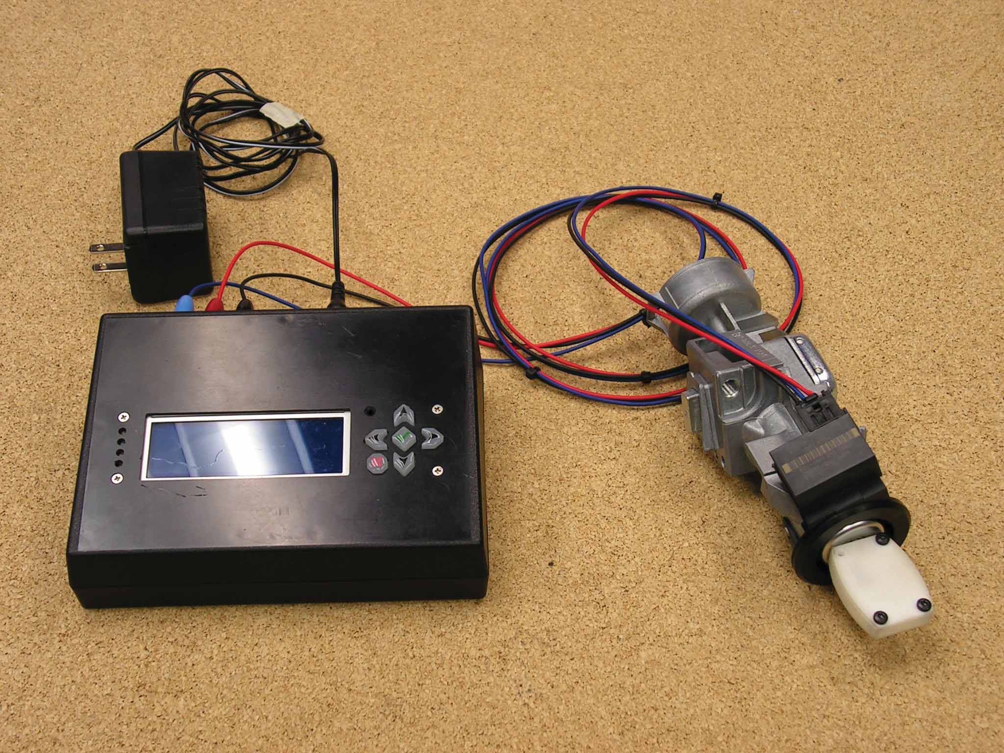
Click to zoom
Application Details
- Equipment Class
- DCD - Part 15 Low Power Transmitter Below 1705 kHz
- Date of Grant
- May 17, 2012
- Application Purpose
- Original Equipment
- Date of Application
- May 17, 2012
- Equipment Note
- Ignition Immobilizer Transmitter
- Frequency Range
- 0.12500000 - 0.12500000
- Company
- NIDEC MOBILITY CORPORATION
- Country
- Japan
Documents & Files
Document Text
Text extracted from the exhibit documents filed with the FCC. Open a document above to read the original.
Users Manual
Rn OMRONAUTOMOTIVEELECTRONICS,INC. 3709OhioAvenue St.Charles,IL60174 Telephone:630-443-6800 FAX:630-443-6898 Thedeviceundertestismanufacturedbythegrantee(OmronAutomotive ElectronicsInc.), andsoldasanOEMproduct.Per47CFR2.909,2.927, 2.931, 2.1033,15.15(b)etc... , thegranteemustensure theend-userhasallapplicableI appropriateoperatinginstructions.Whenend-userinstructionsarereqUired,asinthe caseof thisproduct, thegranteemustnotifytheOEMtonotifytheend-user. OmronAutomotiveElectronicsInc.willsupplythisdocumenttothe reseller/distributordictating whatmustbeincludedintheenduser'smanualforthe commercialproduct. INFORMATIONTOBEINCLUDEDINTHEENDUSER'SMANUAL The followinginformation(inblue)mustbeincludedIntheendproductuser's manualtoensurecontinuedFCCandIndustryCanadaregulatorycompliance. The IDnumbersmustbeIncludedinthemanualIfthedevicelabelisnotreadily accessibletotheenduser.Thecomplianceparagraphsbelowmustbeincluded intheuser'smanual. ****************************************************************************** FCCID:OUC11545917 IC:850K-11545917 ThisdevicecomplieswithPart15 oftheFCCRulesandwithIndustryCanadaIIcence- exempt RSSstandard(s).Operationissubjecttothefollowingtwoconditions: (1)Thisdevicemaynotcauseharmfulinterference, and (2)Thisdevicemustacceptanyinterferencereceived,includinginterferencethat maycauseundesiredoperation. LepresentappareilestconformeauxCNRd'lndustrieCanadaapp/icablesaux appareilsradio exempts delicence.L'exploitationestButoriseeauxdeUxconditionssulvantes: (1)l'apparellnedoitpasproduiredebroui/lage,et (2)(2)/'utilisateurde/'appareildoitacceptertoutbrouilfageradioelectriquesubi, memesiIebrouillageestsusceptibled'encompromettreIefonctionnement. WARNING:Changesormodificationsnotexpressivelyapprovedbytheparty responsibleforcompliancecouldvoidtheuser'sauthoritytooperatetheequipment. Theterm"Ie:"beforetheradiocertificationnumber onlysignifiesthatIndustryCanada technicalspecificationsweremet. ******************************************************************************
Attestation Statements
Re: Certification for Omron Transmitter Model/PN(s): OUC11545917 FCC ID: OUC11545917 IC: 850K-11545917 POWER OF ATTORNEY A letter granting Valdis V. Liepa the Power of Attorney is on file and can be provided when so requested. May 17, 2012 Re: Certification for Omron Transmitter Model/PN(s): OUC11545917 FCC ID: OUC11545917 IC: 850K-11545917 STATEMENT OF MODIFICATIONS There were no modifications made to the DUT by this test laboratory. (Also see Section 3.1 of the attached Test Report). _____________________ Valdis V. Liepa Research Scientist
Cover Letter(s)
May 17, 2012 Certification and Engineering Bureau Industry Canada 3701 Carling Avenue, Bldg. 94 Ottawa, Ontario K2H 8S2 Re: Certification for Omron Transmitter Model/PN(s): OUC11545917 FCC ID: OUC11545917 IC: 850K-11545917 Please find enclosed application materials for certification of Omron Transmitter. We tested the device and found it to comply with RSS-GEN/102/210. The product is identified by: IC: 850K-11545917 If there are any questions, suggestions, etc., regarding the application or testing performed, please contact me at the above address or call 734-483-4211, fax 734-647- 2106; e-mail: [email protected]. Sincerely, Valdis V. Liepa Research Scientist May 17, 2012 Federal Communications Commission Equipment Approval Services P.O. Box 358315 Pittsburgh, PA 15251-5315 Re: Certification for Omron Transmitter Model/PN(s): OUC11545917 FCC ID: OUC11545917 IC: 850K-11545917 Please find enclosed application materials for certification of Omron Transmitter. We tested it and found it to comply with FCC Part 15. If there are any questions regarding the application or testing performed, please contact me at the above address or call 734-483-4211, fax 734-647-2106, or e-mail [email protected]. Sincerely, Valdis V. Liepa Research Scientist
Cover Letter(s)
omROn OMRONCorporation 6368NENJO-ZAKA,OKUSA,KOMAKI-CITY, AlCHl485-0802JAPAN PHONE:+81-568-78-6392 FAX:+81-568-78-6179 FederalCommunicationsCommission ApplicationsProcessingBranch 7435OaklandMillsRoad Colombia,MD21046 Re:PowerofAttorneyforValdisV.Liepa ToWhomItMayConcern: OmronCorporationhasappointedDr.Valdis V.Liepa,locatedattheUniversityofMichigan, Department ofEngineeringandComputerScience,AnnArbor,Michigan48109-2122astheagent toactforOmronCorporationintheFCCcertificationprocess. Datedthis By: 30 th dayofApril,2012, (S}g'IlatUre) ShujiYamashita Title:Manager E-mail:[email protected] Onbehalfof:OmronCorporation AutomotiveElectronicComponentsCompany 6368,Nenjo-zaka,Okusa Komaki-city,Aichi Japan 485-0802 Teiephone:+81-568-78-6174 Fax:+81-568-78-6179 omROn OMRONCorporation 6368NENJO·ZAKA,OKUSA,KOMAKI·CITY, AICHI485·0802JAPAN PHONE:+81·568·78·6392 FAX:+81·568·78·6179 FederalCommunicationsCommission ApplicationsProcessingBranch 7435OaklandMills Road Colombia,MD21046 Re:LetterofAgencyforFCCComplianceTesting Pleasebeadvised thatOmronCorporationauthorizesDr.ValdisV.LiepaoftheUniversityof Michigan,DepartmentofElectricalEngineeringandComputerScience,AnnArbor,Michigan,to act onourbehalfinfrontoftheFederalCommunicationsCommissionwithrespecttoallmatters relatingtocertification. Anti-DrugAbuseCertification: I furthercertifythatnoparty(asdefinedin1.2002ofCFR47,1992)tothisapplication,including myself, issubjecttoa denialoffederalbenefits,thatincludesFCCbenefits,pursuanttoSection 5301oftheAntiDrugAbuseAct of1988,21U,S.c.853(a). Datedthis By: 30 th dayofApril,2012. ~0"v\. ShujiYamashita Title:Manager E-mail:[email protected] Onbehalfof:OmronCorporation AutomotiveElectronicComponentsCompany 6368,Nenjo-zaka,Okusa Komaki-city,Aichi Japan 485-0802 Telephone:+81-568-78-6174 Fax:+81-568-78-6179 omRon OMRONAUTOMOTIVEELECTRONICS,INC. 3709OhiOAvenue Sl.Charles,lL60174 Telephone:630-443-6800 FAX:630-443-6898 Attn:DirectorofCertification AuthoritvtoActasAgent I appointDr.ValdisV.Liepatoactasouragentinthepreparationofthisapplicationfor equipmentcertification.I certifythatsubmitteddocumentsproperlydescribethedevice or systemforwhichequipmentcertificationis sought. Ialsocertifythateachunitmanufactured, importedormarketed,asdefinedinIndustryCanada'sregulationswillhaveaffixedtoita labelidenticaltothatsubmittedforapprovalwiththisapplication. Forinstanceswhereourauthorizedagentsignstheapplicationforcertificationonourbehalf, I acknowledgethatallresponsibilityforcomplyingwiththetermsandconditionsfor Certification,asspecifiedbyAmericanCertificationBody,stillresideswith Omron AutomotiveElectronicsInc_,3709OhioAvenue,St.Charles,Illinois,60174,United States. Datedthis By: Title: email: 8 th dayof A /"(Signature) EMCEngineer [email protected] MattColburn Onbehalfof:OmronAutomotiveElectronicsInc. Telephone:+16304436800x347 Fax:N/A omRon OMRONAUTOMOTIVEELECTRONICS,INC. 3709OhioAvenue Sl.Charles,IL60174 Telephone:630-443-6800 FAX:630-443-6898 IndustryCanada 1241ClydeAve. Ottawa,OntarioK2C1Y3 Re:PowerofAttorneyforValdis V,Liepa ToWhomIt MayConcern: OmronAutomotiveElectronicsInc.hasappointedDr.ValdisV.Liepa,locatedatthe UniversityofMichigan,DepartmentofEngineeringandComputerScience,AnnArbor, Michigan48109-2122astheagenttoactforOmronAutomotiveElectronicsInc.intheIC certificationprocess, Datedthis By: Title: email: EMC Engineer [email protected] MattColburn Onbehalfof:OmronAutomotiveElectronicsInc. Telephone: +16304436800x347 Fax:N/A
Cover Letter(s)
Re: Certification for Omron Transmitter Model/PN(s): OUC11545917 FCC ID: OUC11545917 IC: 850K-11545917 ANTENNA LISTING & STATEMENT INFORMATION The model OUC11545917 transmitter is to employ only antenna coil DS5T-15607-AA or antenna coil DS5T-15607-BA. One of these antennas will be permanently affixed within the OUC11545917 prior to shipment to the OEM installer, depending on which of the two ignition lock cylinders (as tested) it is to be affixed to. As these antennas are non-removable and assembled with the product by the manufacturer prior to shipment, no OEM or end-user warnings about the selection of proper antennas are necessary.
Cover Letter(s)
Re: Certification for Omron Transmitter FCC ID: OUC11545917 IC: 850K-11545917 REQUEST FOR CONFIDENTIALITY Pursuant to FCC 47 CRF 0.457(d) and 0.459 and IC RSP-100, Section 10, Omron requests that a part of the subject application be held confidential. Omron has spent substantial effort in developing this product and it is one of the first of its kind in industry. Having the subject information easily available to "competition" would negate the advantage they have achieved by developing this product. Not protecting the details of the design will result in financial hardship. Type of Confidentiality Requested Exhibit Short Term Permanent (1) ID Label & Location Short Term Permanent (3) External Photos Short Term Permanent 1 (4) Block Diagram Short Term Permanent (5) Schematics Short Term Permanent (7) Test Setup Photos Short Term Permanent (8) User’s Manual Short Term Permanent (9) Internal Photos Short Term Permanent (10) Parts List & Placement Short Term Permanent (11) RF Exposure Short Term Permanent (12) Description of Operation 1. Block Diagram includes internal oscillator frequency information that the manufacturer considers to be proprietary. Permanent Confidentiality: Omron requests the exhibits listed above as permanently confidential be permanently withheld from public review. Short-Term Confidentiality (FCC Only): Omron requests the exhibits selected above as short term confidential be withheld from public view for a period of 45 days from the date of the Grant of Equipment Authorization and prior to marketing. If there are any questions regarding this request, please contact me at the above address or call 734-483-4211, fax 734-647-2106 or e-mail [email protected]. Sincerely, Valdis V. Liepa, Research Scientist University of Michigan
External Photos
DUT with Harness + test box, empoying Antenna DS5T-15607-AA and Plastic Lock Cylinder DUT with Harness + test box, empoying Antenna DS5T-15607-BA and Metal Lock Cylinder
Internal Photos
DUT with Antenna DS5T-15607-AA DUT with Antenna DS5T-15607- B A
Operational Description
Description of Operation The ITM is a component of the Ford Passive Anti-Theft System (PATS) and is the interface between the transponder located in the key and the vehicle Body Control Module (BCM). The transponder derives its energy from the 125 kHz ASK LF waveform. The transceiver has three hard wire connections, PWR, GND, and LIN. PWR is supplied by switched ignition when the vehicle key is inserted in the lock cylinder and in the Run/Start positions. LIN communication is a dedicated node between the ITM and BCM. The BCM is the master device and the ITM is the slave. The transceiver antenna is formed by a coil connected in series with a capacitor to form a series resonant circuit. An internal H-bridge circuit drives the antenna differentially from the PJF7992 IC. Block Diagram 3 Pin Connector Reverse Battery Protection ESD Suppression PJF7992 ANTENNA COIL LIN LIN PWR PWR GND Ceramic Resonator Freq.=4MHz
Test Report
University of Michigan Radiation Laboratory FCC Part 15, IC RSS-210/Gen - Test Report No. 417124-632 Page 1 of 14 The University of Michigan Radiation Laboratory 3228 EECS Building Ann Arbor, MI 48109-2122 Tel: (734) 764-0500 Fax: (734) 647-2106 Measured Radio Frequency Emissions From Omron Transmitter FCC ID: OUC11545917 IC: 850K-11545917 Test Report No. 417124-632 May 17, 2012 Copyright © 2012 For: Omron Corporation 6368, Nenjo-zaka, Okusa, Komaki-city, Aichi, Japan 485-0802 Contact: Shuji Yamashita [email protected] Phone: +81-568-78-6174 Fax: +81-568-78-6179 Testing supervised by: Measurements made by: Valdis V. Liepa Report Approved by:__________________________ Valdis V. Liepa Test report written by: Valdis V. Liepa Research Scientist Summary Tests for compliance with FCC Regulations, CFR 47, Part 15 and with Industry Canada RSS-210/Gen, were performed on a Omron, FCC ID: OUC11545917, IC: 850K-11545917. This device under test (DUT) is subject to the rules and regulations as a Transmitter. In testing completed on May 16, 2012, the DUT tested met the allowed specifications for radiated emissions by 39.7 dB. Conducted emissions are not subject to regulation as the DUT is powered by a 12 VDC vehicular power system. University of Michigan Radiation Laboratory FCC Part 15, IC RSS-210/Gen - Test Report No. 417124-632 Page 2 of 14 Table of Contents 1. Introduction ...................................................................................................................................... 3 2. Equipment Used ............................................................................................................................... 3 3. Device Under Test ........................................................................................................................... 4 3.1 Description & Block Diagram .............................................................................................. 4 3.2 Samples & Variants .............................................................................................................. 4 3.3 Modes of Operation .............................................................................................................. 4 3.4 Exemptions ........................................................................................................................... 4 3.5 EMC Relevant Modifications ............................................................................................... 4 4. Emissions Limits .............................................................................................................................. 5 4.1 Radiated Emissions Limits .................................................................................................... 5 5. Measurement Procedures ................................................................................................................. 6 5.1 Semi-Anechoic Chamber Radiated Emissions ...................................................................... 6 5.2 Outdoor Radiated Emissions ................................................................................................. 6 5.3 Radiated Field Computations ................................................................................................ 6 5.4 Indoor Power Line Conducted Emissions ............................................................................. 6 5.5 Supply Voltage Variation ...................................................................................................... 7 6. Test Results ...................................................................................................................................... 7 6.1 Radiated Emissions ............................................................................................................... 7 6.1.1 Correction for Pulse Operation ......................................................................................... 7 6.1.2 Emission Spectrum ........................................................................................................... 7 6.1.3 Emission Bandwidth ......................................................................................................... 7 6.1.4 Supply Voltage and Supply Voltage Variation ................................................................. 7 6.2 Conducted Emissions ............................................................................................................ 7 University of Michigan Radiation Laboratory FCC Part 15, IC RSS-210/Gen - Test Report No. 417124-632 Page 3 of 14 1. Introduction This Omron Transmitter was tested for compliance with FCC Regulations, Part 15, adopted under Docket 87-389, April 18, 1989 as subsequently amended, and with Industry Canada RSS-210/Gen, Issue 8. Tests were performed at the University of Michigan Radiation Laboratory Willow Run Test Range following the procedures described in ANSI C63.4-2003 "Methods of Measurement of Radio-Noise Emissions from Low-Voltage Electrical and Electronic Equipment in the Range of 9 kHz to 40 GHz". The Site description and attenuation characteristics of the Open Site facility are on file with FCC Laboratory, Columbia, Maryland (FCC Reg. No: 91050) and with Industry Canada, Ottawa, ON (File Ref. No: IC 2057A-1). 2. Equipment Used The test equipment commonly used in our facility is listed in Table 2.1. Except where indicated as a pre- test, monitoring, or support device; all equipment listed below is a part of the University of Michigan Radiation Laboratory (UMRL) quality system. This quality system has been established to ensure all equipment has a clearly identifiable classification, calibration expiry date, and that all calibrations are traceable to national standards. Table 2.1 Test Equipment. Test Instrument Used Manufacturer/Model Q Number Spectrum Analyzer (9kHz-26GHz) Hewlett-Packard 8593E, SN: 3412A01131 HP8593E1 Spectrum Analyzer (9kHz-6.5GHz) Hewlett-Packard 8595E, S…
Text truncated - open the document above for the full version.
Contact Information
Applicant
Shinya Takenouchi(Manager)
Technical Contact
University of Michigan EECSValdis Liepa
[email protected]734 483 4211
1301 Beal Ave. · Ann Arbor, Michigan · United States
Test Firm
University of MichiganValdis Liepa
Technical Specifications
| # | Rule Parts | Frequency Range | Power Output |
|---|---|---|---|
| 1 | 15C | 0.125 MHz - 0.125 MHz | - |
Other Applications from NIDEC MOBILITY CORPORATION
OUCTPMS1R
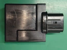
Jul 02, 2023TPMS ECU
Equipment Class
CYY - Communications Receiver used w/Pt 15 Transmitter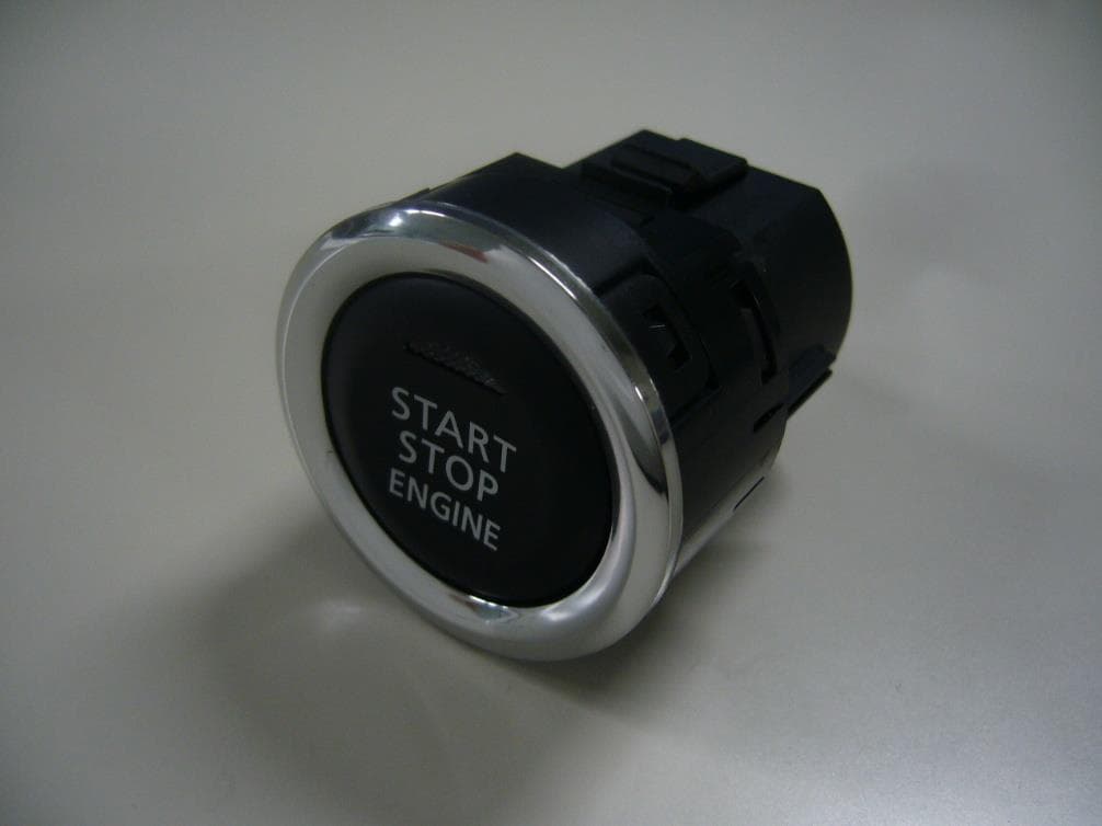
OUCR328E
Nov 29, 2020Transmitter of Keyless Entry System
Equipment Class
DCD - Part 15 Low Power Transmitter Below 1705 kHz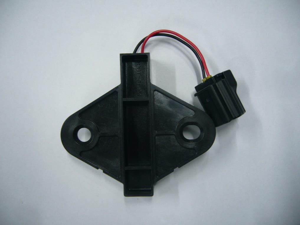
OUCR515E
Nov 29, 2020Transmitter of Keyless Entry System
Equipment Class
DCD - Part 15 Low Power Transmitter Below 1705 kHz
OUC744M-KEY-N
Sep 23, 2020Keyless Operation Key (FOB)
Equipment Class
DSC - Part 15 Security/Remote Control Transmitter
OUCGGM-M018
Aug 04, 2020ETACS
Equipment Class
CYY - Communications Receiver used w/Pt 15 Transmitter