OUCG8D-246S-AKeyless Entry System (Transmitter)
NIDEC MOBILITY CORPORATION
Click to zoom
Application Details
- Equipment Class
- DSC - Part 15 Security/Remote Control Transmitter
- Date of Grant
- May 07, 2003
- Application Purpose
- Original Equipment
- Date of Application
- May 07, 2003
- Equipment Note
- Keyless Entry System (Transmitter)
- Frequency Range
- 315.10000000 - 315.10000000
- Company
- NIDEC MOBILITY CORPORATION
- Country
- Japan
Documents & Files
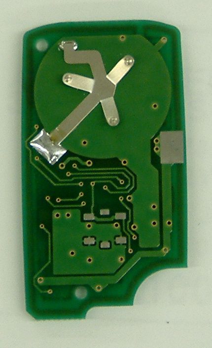
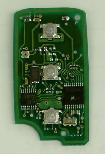
Document Text
Text extracted from the exhibit documents filed with the FCC. Open a document above to read the original.
Users Manual
50J1 Transmitter, RF Keyless Entry System 50J1NP Table of contents 1. Constitution of the Radio Frequency Keyless Entry system with Door Lock Controller for vehicle ...................................................................................... 1 2. User’s manual (provisionally) .......................................................................... 2 3. Block diagram ................................................................................................ 3 4. Specification ................................................................................................... 4 5. Features .......................................................................................................... 5 6. PCB 6.1.1 Circuit diagram ........................................................................................... 6 6.2.1 Parts layout (front)....................................................................................... 7 6.2.2 Parts layout (back)....................................................................................... 8 6.3.1 Pattern layout (front)................................................................................... 9 6.3.2 Pattern layout (back)................................................................................... 10 6.4 Parts list ...................................................................................................... 11 1. Constitution of the Radio Frequency Keyless Entry System with Door Lock Controller for vehicle The radio frequency keyless entry is a system that it controls locking and unlocking the door by wireless remote controller. This system consists of two components. The TRANSMITTER is a device that transmits the signal when the button is pressed. The transmission signal consists of several synchronous codes, unique identification code, and security code and function code. The RECEIVER is fixed inside the vehicle. It works intermittently to prevent the battery exhaustion. When the receiver detects the synchronous code, it runs continuously to receive the signals completely. After receiving the signal, the receiver decides which operation will be performed. The user can select the following operations by pressing the button of the remote transmitter. OPERATION ACTION LOCK Lock the door UNLOCK Unlock the door (the driver side first, then all doors) PANIC MODE Flush the light, flush the small light, and beep the horn. it continues 30 seconds This receiver also controls wired operation. When the key is in the driver’s side key cylinder, all doors will Unlock if the key is turned to UNLOCK and hold more than one second. In case of the operation time is shorter, the only driver’s side door is mechanically unlocked. It is also available to control the door lock status by using the remote door control switch (both driver’s and passenger’s side). Transmitter f =315.1MHz -1- - 2. User’s manual (provisionally) REMOTE TRANSMITTER You can lock and unlock your vehicle with the remote transmitter. LOCK When you push the LOCK button, all the doors will lock. You cannot lock any of the doors with the remote transmitter if any door is open or the key is in the ignition switch. UNLOCK When you push the UNLOCK button once , only the driver’s door unlocks. The remaining door unlock when you push the button a second time. If you unlock the doors with the remote transmitter, but do not open any of the doors within 30 seconds, the doors will automatically relocked. You cannot unlock any of the doors with the remote transmitter if the key is in the ig n i t i o n s w i t c h . PANIC MODE Panic mode allows you to remotely sound your vehicle’s horn to attract attention. To activate this mode , press and hold the PANIC button for about one seconds. Your vehicle’s horn will beep for about 30 seconds. To cancel Panic mode before 30 seconds , press any button on the remote transmitter. You can also turn the ignition switch is in ON. -2- - 3. Block diagram This is the block diagram concerning to the transmitter Antenna LOCK UNLOCK Data EEPROM PANIC 8BIT CPU OUT PUT 315.1MHz Figure 3.1 block diagram of the transmitter Switch combination MODEL NAME SW QTY LOCK UNLOCKPANIC G8D-246S-A(50J1) 3 G8D-246S-A-NP(50J1NP) 2 -3- - 4. Specification 4.1 CPU Type uPD789860(8bit) Manufacturer: NEC Corporation ROM 4K bytes RAM 128 bytes EEPROM 16 bytes Clock frequency 5MHz Clock frequency generation Ceramic resonator Package 20pin SOP 4.2 RF block Carrier frequency 315.1MHz Frequency generation Crystal resonator Modulation FSK Bit transmission rate 1000bps or 2000bps Bandwidth 120KHz RF output power (field strength) 10.8uW6000V/mat3mmax 4.3 Others Dimension 55.7mm33.8mm11.8mm Weight 18.0g Battery Lithium cell (CR2032) Manufacturer: Maxell or Panasonic Operation Voltage DC 3V, 220mAh Operation temperature -20 ~ +60 -4- - 5. Features 5.1 Transmission frame The transmission begins immediately in case of LOCK or UNLOCK button is pressed. The transmission frame consists of the synchronous frame and the data frame. The synchronous frame has 81 synchronous codes that it will be used for the receiver to wake up. The data frame consists of 28-bit length identification code, 16-bit security code and function code. 1600 million different identification codes are available. The security code is always changed in case of any of the buttons is pressed. The transmission time is typically 370 milliseconds. 5.2 Battery saving To prevent the battery exhaustion, the microcomputer of the transmitter is usually inactive. When the button will be pressed, the microcomputer wakes up immediately and judges which button is pressing. Then the microcomputer constructs the transmission frame and radiates it from the antenna. After transmitting, the microcomputer switches stand-by mode by itself. -5- - 6. PCB 6.1 Circuit diagram Figure 6.1.1 Circuit diagrams -6- - 6.2 Parts layout Figure 6.2.1 Parts layout (front) -7- - Figure 6.2.2 Parts layout (back) -8- - 6.3 Pattern layou…
Text truncated - open the document above for the full version.
Users Manual
1. For USA This device complies with part 15 of the FCC Rules. Operation is subject to the following two conditions: (1) This device may not cause harmful interference, and (2) this device must accept any interference received, including interference that may cause undesired operation. CAUTION Changes or modifications not expressly approved by the party responsible for compliance could void the user’s authority to operate the equipment. 2. For Canada This device complies with Industry Canada Standard RSS-210. Operation is subject to the following two conditions: (1) this device may not cause interference, and (2) this device must accept any interference, including interference that may cause undesired operation of the device The term “IC:” before the certification/registration number only signifies that the Industry Canada technical specifications were met.
Block Diagram
3. Block diagram This is the block diagram concerning to the transmitter Antenna LOCK UNLOCK Data EEPROM PANIC 8BIT CPU OUT PUT 315.1MHz Figure 3.1 block diagram of the transmitter Switch combination MODEL NAME SW QTY LOCK UNLOCKPANIC G8D-246S-A(50J1) 3 G8D-246S-A-NP(50J1NP) 2 -3- -
Operational Description
4. Specification 4.1 CPU Type uPD789860(8bit) Manufacturer: NEC Corporation ROM 4K bytes RAM 128 bytes EEPROM 16 bytes Clock frequency 5MHz Clock frequency generation Ceramic resonator Package 20pin SOP 4.2 RF block Carrier frequency 315.1MHz Frequency generation Crystal resonator Modulation FSK Bit transmission rate 1000bps or 2000bps Bandwidth 120KHz RF output power (field strength) 10.8uW6000V/mat3mmax 4.3 Others Dimension 55.7mm33.8mm11.8mm Weight 18.0g Battery Lithium cell (CR2032) Manufacturer: Maxell or Panasonic Operation Voltage DC 3V, 220mAh Operation temperature -20 ~ +60 -4- - 5. Features 5.1 Transmission frame The transmission begins immediately in case of LOCK or UNLOCK button is pressed. The transmission frame consists of the synchronous frame and the data frame. The synchronous frame has 81 synchronous codes that it will be used for the receiver to wake up. The data frame consists of 28-bit length identification code, 16-bit security code and function code. 1600 million different identification codes are available. The security code is always changed in case of any of the buttons is pressed. The transmission time is typically 370 milliseconds. 5.2 Battery saving To prevent the battery exhaustion, the microcomputer of the transmitter is usually inactive. When the button will be pressed, the microcomputer wakes up immediately and judges which button is pressing. Then the microcomputer constructs the transmission frame and radiates it from the antenna. After transmitting, the microcomputer switches stand-by mode by itself. -5- -
Schematics
6. PCB 6.1 Circuit diagram Figure 6.1.1 Circuit diagrams -6- -
Contact Information
Applicant
Shinya Takenouchi(Manager)
Test Firm
Japan Quality Assurance Org.Tetsuo Kato
Technical Specifications
| # | Rule Parts | Frequency Range | Power Output |
|---|---|---|---|
| 1 | 15.231 | 315.1 MHz - 315.1 MHz | - |
Other Applications from NIDEC MOBILITY CORPORATION
OUCTPMS1R
Jul 02, 2023TPMS ECU
Equipment Class
CYY - Communications Receiver used w/Pt 15 Transmitter
OUCR328E
Nov 29, 2020Transmitter of Keyless Entry System
Equipment Class
DCD - Part 15 Low Power Transmitter Below 1705 kHz
OUCR515E
Nov 29, 2020Transmitter of Keyless Entry System
Equipment Class
DCD - Part 15 Low Power Transmitter Below 1705 kHz
OUC744M-KEY-N
Sep 23, 2020Keyless Operation Key (FOB)
Equipment Class
DSC - Part 15 Security/Remote Control Transmitter
OUCGGM-M018
Aug 04, 2020ETACS
Equipment Class
CYY - Communications Receiver used w/Pt 15 Transmitter