OUCG8D-333A-ARemote Keyless Entry
NIDEC MOBILITY CORPORATION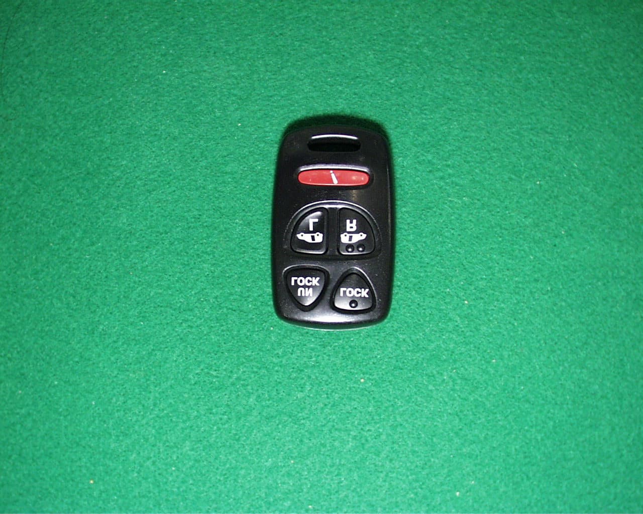
Click to zoom
Application Details
- Equipment Class
- DSC - Part 15 Security/Remote Control Transmitter
- Date of Grant
- Sep 22, 2001
- Application Purpose
- Original Equipment
- Date of Application
- Sep 22, 2001
- Equipment Note
- Remote Keyless Entry
- Frequency Range
- 313.85000000 - 313.85000000
- Company
- NIDEC MOBILITY CORPORATION
- Country
- Japan
Documents & Files
Document Text
Text extracted from the exhibit documents filed with the FCC. Open a document above to read the original.
Users Manual
! CAUTION The remote control switch is a precision electronic device. Therefore, pay attention to the following: Do not impose shock on the remote control switch. Keep the remote control switch dry. Do not disassemble the remote control switch. Your keyless entry system operates on a radio frequency subject to Federal Communications Commission (FCC) rules and Industry Canada rules. This device complies with Part 15 of the FCC Rules. Operation is subject to the following tow conditions. (1) This device may not cause harmful interference, and (2) This device must accept any interference received, including interference that may cause undesired operation of the device. “Complies with RSS-210 of Industry Canada.” NOTICE This equipment has been tested and found to comply with the limits for a Class B device, pursuant to part 15 of the FCC Rules, These limits are designed to provide reasonable protection against harmful interference in a residential installation. This equipment generates, uses and can radiate radio frequency energy and, if not installed and used in accordance with the instruction, may cause harmful interference to radio communications However there is no guarantee that interference will not occur in particular installation. If this equipment dose cause harmful interference to radio or radio or television reception, which can be determined by turning the equipment off and on, the user is encouraged to try to correct the interference by one or more of the following measures. Reorient or relocate the receiving antenna. Increase the separation between the equipment and receiver. Connect the equipment into an outlet on a circuit different from that to which the receiver is connected Consult the dealer or an experienced radio/TV technician for help. FCC WARNING Changes or modifications not expressly approved by the party responsible for compliance could void the user’s authority to operate the equipment.
External Photos
External photo (front view) Model name: G8D-333A-A FCC ID: OUCG8D-333A-A External photo (back view) Model name: G8D-333A-A FCC ID: OUCG8D-333A-A
Internal Photos
Internal photo Internal view Model name: G8D-333A-A FCC ID: OUCG8D-333A-A Internal photo Circuit Board (front) Model name: G8D-333A-A FCC ID: OUCG8D-333A-A Internal photo Circuit Board (back) Model name: G8D-333A-A FCC ID: OUCG8D-333A-A
Operational Description
1. Constitution of the Radio Frequency Keyless Entry System with Door Lock Controller for vehicle The radio frequency keyless entry is a system that it controls locking and unlocking the door by wireless remote controller. This system consists of two components. The TRANSMITTER is a device that transmits the signal when the button is pressed. The transmission signal consists of several synchronous codes, unique identification code, and security code and function code. The RECEIVER is fixed inside the vehicle. It works intermittently to prevent the battery exhaustion. When the receiver detects the synchronous code, it runs continuously to receive the signals completely. After receiving the signal, the receiver decides which operation will be performed. The user can select the following operations by pressing the button of the remote transmitter. OPERATION ACTION LOCK Lock the door UNLOCK unlock the door (the driver side first, then all doors) PANIC The horn is beeped, and the headlight and flasher are blinked SLIDE DOOR LEFT Open or close the left slide door. SLIDE DOOR RIGHT Open or close the right slide door. This receiver also controls wired operation. It is available to control the door lock status by using the silicon switch or the remote door control switch (both driver’s and passenger’s side). Transmitter f =313.85MHz -1- - 4. Specification 4.1 CPU Type uPD789860 (8bit) Manufacturer: NEC Corporation ROM 4K bytes RAM 128 bytes EEPROM 32 bytes Clock frequency 5MHz Clock frequency generation Ceramic resonator Package 20pin SSOP 4.2 RF block Carrier frequency 313.8~313.9MHz Frequency generation Crystal resonator Modulation FSK Bit transmission rate 1000bps or 2000bps Bandwidth 120KHz RF output power (field strength) 6000μV/m 4.3 Others Dimension 58.2mm×30.7mm×12.6mm Weight 17g Battery Lithium cell (CR2025) Manufacturer: MATSUSHITA Battery corporation Operation Voltage DC 3V, 20mA Operation temperature -20°C ~ +60°C -4- - 5. Features 5.1 Transmission frame The transmission begins immediately in case of LOCK or UNLOCK button is pressed. The transmission frame consists of the synchronous frame and the data frame. The synchronous frame has 81 synchronous codes that it will be used for the receiver to wake up. The data frame consists of 28-bit length identification code, 16-bit security code and function code. 1600 million different identification codes are available. The security code is always changed in case of any of the buttons is pressed. The transmission time is typically 370 milliseconds. 5.2 Battery saving To prevent the battery exhaustion, the microcomputer of the transmitter is usually inactive. When the button will be pressed, the microcomputer wakes up immediately and judges which button is pressing. Then the microcomputer constructs the transmission frame and radiates it from the antenna. After transmitting, the microcomputer switches stand-by mode by itself. -5- -
Test Report
Test report Our reference : 22BE0028-YW-1 Page: 2 of 11 Issued date: September 14, 2001 FCC ID: OUCG8D-333A-A Testing Laboratory A-pex International Co., Ltd. Telephone:+81 596 39 1485 108 Yokowa-cho, Ise-shi Mie-ken 516-1106 JAPANFacsimile:+81 596 39 0232 Table of Contents Page 1 GENERAL INFORMATION3 1.1 Product Description4 1.2 Test Specification4 1.3 Methods & Procedures4 1.4 Test Location4 2 SYSTEM TEST CONFIGURATION5 2. 1 Operation Environment 5 2.2 Justification5 2. 3 EUT Exercise Software5 2.4 Test Procedure5 Figure 2.1 Configuration of Tested System6 3 RADIATED EMISSION DATA7 3.1 Field Strength Calculation7 2.2 –20dB Bandwidth7 3.3 Measurement Uncertainty8 4 TEST EQUIPMENT USED9 5 MEASUREMENT PHOTOS 10 Figure 5.1 Radiated Measurement Photos 10 APPENDIX 11 A:Test Data A1 – A3 Test report Our reference : 22BE0028-YW-1 Page: 3 of 11 Issued date: September 14, 2001 FCC ID: OUCG8D-333A-A Testing Laboratory A-pex International Co., Ltd. Telephone:+81 596 39 1485 108 Yokowa-cho, Ise-shi Mie-ken 516-1106 JAPANFacsimile:+81 596 39 0232 1 GENERAL INFORMATION Applicant: OMRON CORPORATION Trade Name: OMRON Address: 6368 Nenjo-Zaka, Okusa, Komaki-City, Aichi 485-0802 Japan Telephone Number: +81-568-78-6170 Facsimile Number: +81-568-78-6179 Regulation(s): FCC Part 15 Subpart C Section 15.231 Model Number: G8D-333A-A FCC ID: OUCG8D-333A-A Serial Number: Sample No.1 Condition of EUT: Engineering Prototype Kind of Equipment : Keyless Entry System (Transmitter) Tested Date: September 11, 2001 Receipt Date of Sample : September 7, 2001 Report File Number : 22BE0028-YW-1 Test Site: A-PEX Yokowa No.3 Open Test Site Test report Our reference : 22BE0028-YW-1 Page: 4 of 11 Issued date: September 14, 2001 FCC ID: OUCG8D-333A-A Testing Laboratory A-pex International Co., Ltd. Telephone:+81 596 39 1485 108 Yokowa-cho, Ise-shi Mie-ken 516-1106 JAPANFacsimile:+81 596 39 0232 1.1 Product Description Model: G8D-333A-A(referred to as the EUT in this report) is a Keyless Entry System (Transmitter). The specification is as following : Carrier Frequency : 313.85 MHz Modulation: FSK Other Clock Frequency: 5.0MHz Information antenna: Integral / P.C.B pattern antenna Operation Voltage: Lithium Battery DC 3.0V(CR2025) 1.2 Test Specification Test Specification: FCC Part 15 Subpart C Title: FCC 47CFR Part15 Radio Frequency Device Subpart C Intentional Radiators 15.231 Periodic operation in the band 40.66 – 40.70 MHz and above 70MHz 1.3Methods & Procedures No.ItemTest ProcedureSpecificationRemarks 1 Electric Field Strength of Fundamental Emission ANSI C63.4:1992 15.231 3m 2 Electric Field Strength of Spurious Emission ANSI C63.4:1992 15.205 15.209 15.231 3m 3-20dB BandwidthANSI C63.4:1992 15.231 3m 1.4 Test Location A-PEX International Co.,Ltd. Yokowa No.3 test site 108 Yokowa-cho, Ise-shi, Mie-ken 516-1106 Japan Telephone number: +81-596-39-1485 Facsimile number: +81-596-39-0232 This site has been fully described in a report submitted to FCC office, and listed on September 12, 2000 (Registration number: 90412). *NVLAP Lab. code : 200109-0 Test report Our reference : 22BE0028-YW-1 Page: 5 of 11 Issued date: September 14, 2001 FCC ID: OUCG8D-333A-A Testing Laboratory A-pex International Co., Ltd. Telephone:+81 596 39 1485 108 Yokowa-cho, Ise-shi Mie-ken 516-1106 JAPANFacsimile:+81 596 39 0232 2 SYSTEM TEST CONFIGURATION 2.1 Operation Environment Temperature: See data Humidity: See data 2.2 Justification The system was configured in typical fashion (as a customer would normally use it) for testing. 2.3 EUT Exercise Software The EUT exercise program used during radiated testing was designed to exercise the various system components in a manner similar to typical use. The sequence is used: Operation Mode : Transmitting 2.4 Test Procedure Tabletop Equipment Radiated Emissions EUT was placed on a platform of nominal size, 1m by 1m, raised 80cm above the conducting ground plane. Test was made with the antenna positioned in both the horizontal and vertical planes of polarization. The measurement antenna was varied in height above the conducting ground plane to obtain the maximum signal strength. The measurement distance was 3m. Test report Our reference : 22BE0028-YW-1 Page: 6 of 11 Issued date: September 14, 2001 FCC ID: OUCG8D-333A-A Testing Laboratory A-pex International Co., Ltd. Telephone:+81 596 39 1485 108 Yokowa-cho, Ise-shi Mie-ken 516-1106 JAPANFacsimile:+81 596 39 0232 Figure2.1 Configuration of Tested System Front View (1):EUT Top View (1):EUT *Test data was taken under worse case conditions. No.ItemModel numberSerial numberManufacturerFCC ID 1Keyless Entry System (Transmitter) G8D-333A-A Sample No.1OMRON Corporation OUCG8D-333A-A Test report Our reference : 22BE0028-YW-1 Page: 7 of 11 Issued date: September 14, 2001 FCC ID: OUCG8D-333A-A Testing Laboratory A-pex International Co., Ltd. Telephone:+81 596 39 1485 108 Yokowa-cho, Ise-shi Mie-ken 516-1106 JAPANFacsimile:+81 596 39 0232 3 RADIATED EMISSION DATA The initial step in collecting radiated data was a spectrum analyzer peak scan of the measurement range (30MHz-3200MHz). The final data was reported in the worst-case emissions. The minimum margin to the limit is as follows : No Ant Pol Freq [MHz] Reading [dB V] Antenna Factor [dB] Cable Loss [dB] ATT [dB] AMP Gain [dB] Result [dB V/m] Limit [dB V/m] Margin [dB] Remark 1 H 313.89 76.2 14.4 3.6 5.8 27.6 72.4 75.6 3.2Fundamental 2 H1255.59 53.3 26.1 4.9 0.0 35.1 49.2 55.6 6.4Spurious Remark: Below 1GHz: Test Receiver Setting: QP Detect / IF Band width 120kHz Above 1GHz: Spectrum Analyzer Setting: AV Detect/ RBW 1MHz and VBW 10Hz) 3.1 Field Strength Calculation The field strength is calculated by adding the Antenna Factor, Cable Factor and Antenna Pad, and subtracting the Amplifier Gain from the measured reading. The sample calculation is as follows : FS = RA + AF + CF + AT - AG where FS = Field Strength RA = Receiver Amplitude AF = Antenna Factor CF = Cable Factor AT = Antenna Pad AG = Amplifier Gain Assume a receiv…
Text truncated - open the document above for the full version.
Test Setup Photos
Test report Our reference : 22BE0028-YW-1 Page: 10 of 11 Issued date: September 14, 2001 FCC ID: OUCG8D-333A-A Testing Laboratory A-pex International Co., Ltd. Telephone:+81 596 39 1485 108 Yokowa-cho, Ise-shi Mie-ken 516-1106 JAPANFacsimile:+81 596 39 0232 5 RADIATED MEASUREMENT PHOTOS 5.1 Radiated Measurement Photos
Contact Information
Applicant
Shinya Takenouchi(Manager)
Technical Contact
A-Pex International LtdMakoto Kosaka
[email protected]81-596-39-1485
108 Yokowa-cho · Ise-shi, Mie-ken · Japan
Non-Technical Contact
A-Pex InternationalMotomu Kawano
[email protected]81-596-24-6717
Test Firm
UL Apex Co., Ltd.Toshihiro Ikegami
Technical Specifications
| # | Rule Parts | Frequency Range | Power Output |
|---|---|---|---|
| 1 | 15.231 | 313.85 MHz - 313.85 MHz | - |
Other Applications from NIDEC MOBILITY CORPORATION
OUCTPMS1R
Jul 02, 2023TPMS ECU
Equipment Class
CYY - Communications Receiver used w/Pt 15 Transmitter
OUCR328E
Nov 29, 2020Transmitter of Keyless Entry System
Equipment Class
DCD - Part 15 Low Power Transmitter Below 1705 kHz
OUCR515E
Nov 29, 2020Transmitter of Keyless Entry System
Equipment Class
DCD - Part 15 Low Power Transmitter Below 1705 kHz
OUC744M-KEY-N
Sep 23, 2020Keyless Operation Key (FOB)
Equipment Class
DSC - Part 15 Security/Remote Control Transmitter
OUCGGM-M018
Aug 04, 2020ETACS
Equipment Class
CYY - Communications Receiver used w/Pt 15 Transmitter