OUCG8D-365MTire Pressure Monitor Receiver
NIDEC MOBILITY CORPORATION
Click to zoom
Application Details
- Equipment Class
- CYY - Communications Receiver used w/Pt 15 Transmitter
- Date of Grant
- Apr 23, 2003
- Application Purpose
- Original Equipment
- Date of Application
- Apr 23, 2003
- Equipment Note
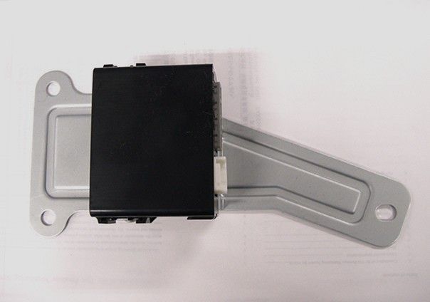
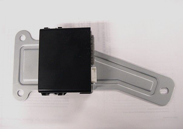
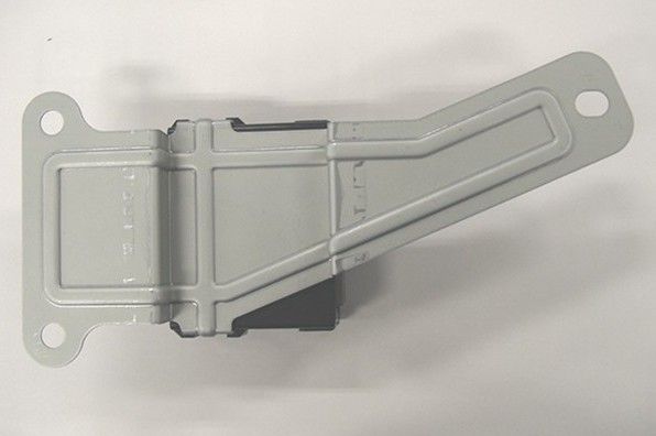
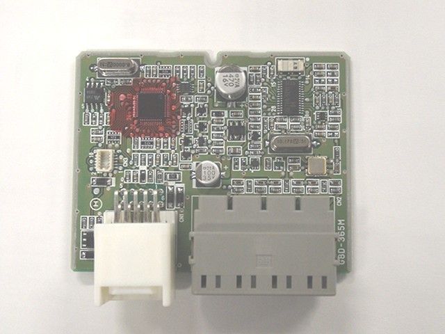
- Tire Pressure Monitor Receiver
- Frequency Range
- 315.00000000 - 315.00000000
- Company
- NIDEC MOBILITY CORPORATION
- Country
- Japan
Documents & Files
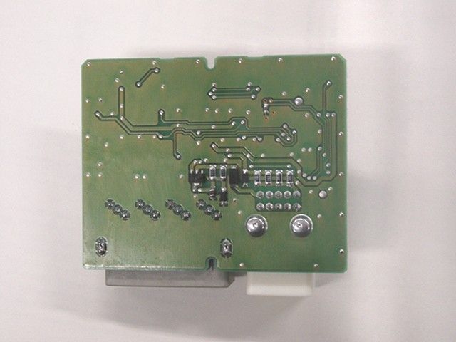
Document Text
Text extracted from the exhibit documents filed with the FCC. Open a document above to read the original.
Users Manual
FCC ID:OUCG8D-365M G8D-365M Receiver, Tire Pressure Monitoring System FCC ID:OUCG8D-365M Table of contents 1. Constitution of the Tire Pressure Monitoring System for vehicle....................... 2 2. User’s manual (provisionally) .......................................................................... 3 3. Block diagram ................................................................................................ 4 4. Specification ................................................................................................... 5 5. Features .......................................................................................................... 6 6. PCB 6.1 Circuit diagram ........................................................................................... 7 6.2 Parts layout (front)...................................................................................... 8 6.3 Pattern layout (front).................................................................................... 9 6.4 Parts layout (back).................................................................................... 10 6.4 Pattern layout (back).................................................................................... 11 6.5 Parts list ...................................................................................................... 12 7. Connector ...................................................................................................... 16 8. Photographs .................................................................................................... 17 - 1 - FCC ID:OUCG8D-365M 1. Constitution of the Tire Pressure Monitoring System for vehicle Tire Pressure Monitoring System is the system that receives the information, from transmitters installed at each tire, about the inflation pressure or temperature of tires detected by the sensor, so that the system can detect the abnormality of tires like fallen inflation pressure. This system consists of transmitter, receiving antenna, and receiver. The transmitter sends information of tire, read by the sensor, in the form of radio wave at constant intervals. The receiver is fixed inside the vehicle. If IG is OFF, it works intermittently to prevent the battery exhaustion. When the receiver detects the synchronous code and IG is ON, it runs continuously to receive the signals completely. If the received code is normal, the system will not inform the user. As shown below, in the case that the transmitter sends information that the tire is in abnormal condition, and that the receiver system has a trouble, the system will inform the user with lighting up Warning bulb. TPMS Warning bulb is lit by the following situations. Bulb disconnection detection outputThe warning light is On for 3 sec. when IG=OFF→ON Tire air pressure warning output (Warning light is ON) System warning output (Warning light is blinking) Pressure sensor 1 CPU R e c e i v i n g c i r c u i t CPU EEPROM Transmission circuit Receiver Transmitter 1 Antenna Transmitter SP Transmitter 2 Transmitter 3 Transmitter 4 Tire Bulb Figure 2-1 System Architecture - 2 - FCC ID:OUCG8D-365M 2. User’s manual (provisionally) Tire inflation pressure warning light This light illuminates if the inflation pressure of any tire (except for compact spare tire) drops while the ignition key is in the “ON” position. It normally illuminates when the ignition key is turned to the “ON” position and goes off a few seconds later. If the warning light illuminates while driving Avoiding hard braking, hard steering, and high speeds, drive to the nearest gas station or authorize car dealer and adjust the tire inflation pressures.(except for compact spare tire) If the warning light blinking while driving It is thought abnormality of the device, go to the check to the nearest car dealer as soon as possible. Whenever the tires and wheels are replaced with new ones Tire inflation pressure sensors must be fitted on the new wheels and their ID codes must be programmed into the system. Have tire and wheel replacement performed by an authorized car dealer to avoid the risk of damaging the tire inflation pressure sensors. If the tire inflation pressure warning-light does not illuminate when the ignition key is turned to the “ON” position the system may be faulty. If the tire inflation pressure warning light illuminates while you are driving, avoid hard braking, hard steering, and high speeds. Otherwise, you could make the vehicle unstable and have a serious accident. The tire inflation pressure warning light may not illuminate immediately in the event of a tire blowout or rapid leak.. - 3 - FCC ID:OUCG8D-365M 3. Block diagram This is the block diagram concerning to the receiver. 16BIT CPU RECEIVING MODULE EEPROM POWER SOURCE(5V) data OUTPUT CIRCUIT Signal of vehicle status input output 12V (car battery) IG1 bulb Figure 3.1 block diagram of the receiver - 4 - FCC ID:OUCG8D-365M 4. Specification 4.1 CPU Type M30102(16bit) Manufacturer: MITSUBISHI ROM 24K bytes RAM 1Kytes Clock frequency 8.00MHz Clock frequency generation Crystal oscillator Package 48pin QFP 4.2 RF block Local clock frequency 325.7MHz Frequency generation Crystal resonator Modulation Single Superheterodyne Bandwidth 200KHz Sensitivity 30dBuV 4.3 Others Dimension 83mm64mm31mm Weight 120g Battery Car Battery (DC 12V) Operation Voltage DC 12V, 20mA Operation temperature -30 ~ +80 - 5 - FCC ID:OUCG8D-365M 5. Features Battery saving The receiver works intermittently to reduce the battery consumption. The microcomupter embedded on the receiver controlls the power supply for the RF circuit. In case of the microcomputer detects the wake-up signal during the power supplied, the microcomputer continue supplying the power until the data frame will be received. - 6 - FCC ID:OUCG8D-365M 6. PCB 6.1 Circuit diagram Figure 6.1 Circuit diagrams - 7 - FCC ID:OUCG8D-365M 6.2 Parts layout (front) Figure 6.2 Parts layout (front) - 8 - FCC ID:OUCG8D-365M 6.3 Pattern layou…
Text truncated - open the document above for the full version.
Block Diagram
FCC ID:OUCG8D-365M 3. Block diagram This is the block diagram concerning to the receiver. 16BIT CPU RECEIVING MODULE EEPROM POWER SOURCE(5V) data OUTPUT CIRCUIT Signal of vehicle status input output 12V (car battery) IG1 bulb Figure 3.1 block diagram of the receiver - 4 -
Contact Information
Applicant
Shinya Takenouchi(Manager)
Test Firm
Japan Quality Assurance Org.Tetsuo Kato
Technical Specifications
| # | Rule Parts | Frequency Range | Power Output |
|---|---|---|---|
| 1 | 15B | 315 MHz - 315 MHz | - |
Other Applications from NIDEC MOBILITY CORPORATION
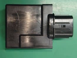
OUCTPMS1R
Jul 02, 2023TPMS ECU
Equipment Class
CYY - Communications Receiver used w/Pt 15 Transmitter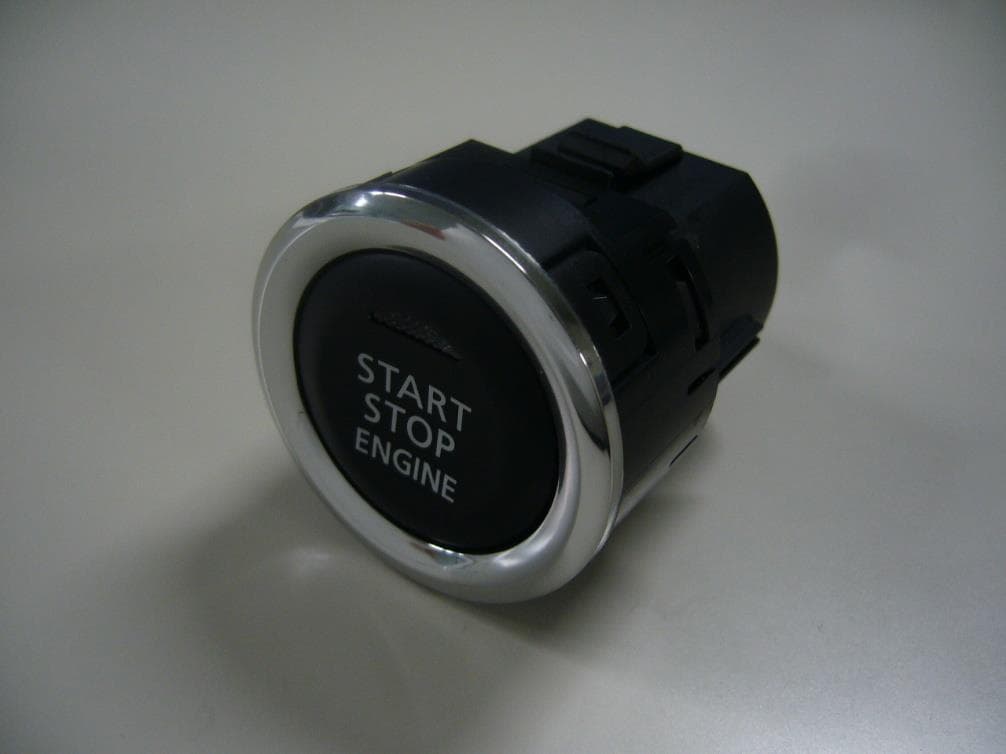
OUCR328E
Nov 29, 2020Transmitter of Keyless Entry System
Equipment Class
DCD - Part 15 Low Power Transmitter Below 1705 kHz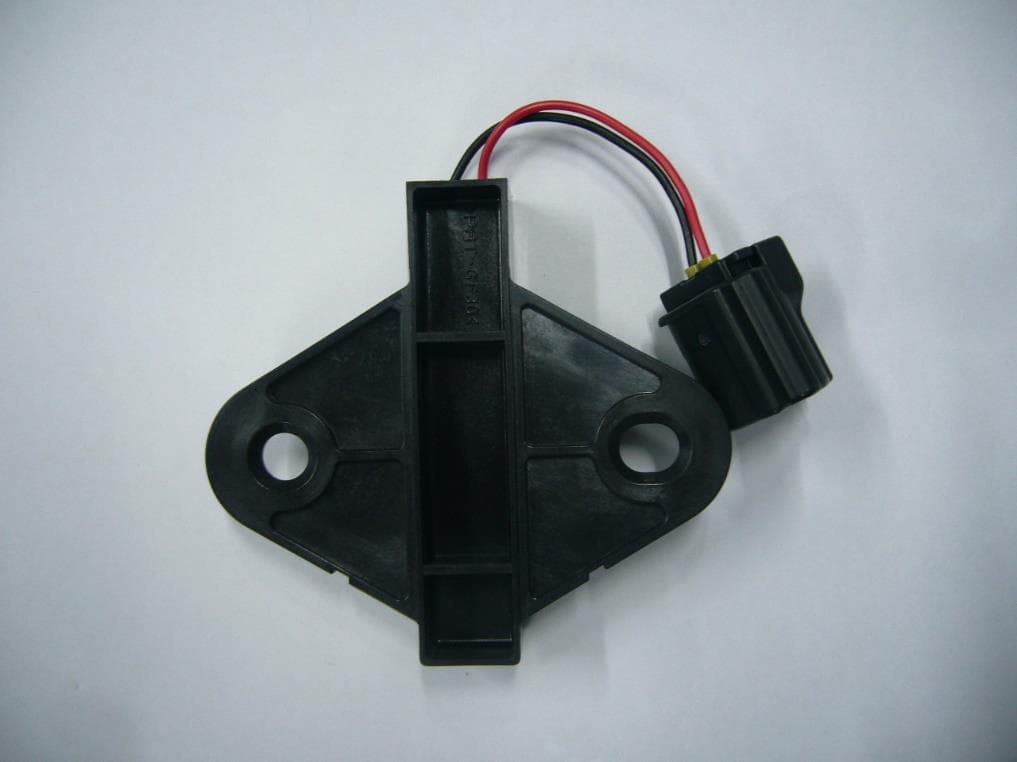
OUCR515E
Nov 29, 2020Transmitter of Keyless Entry System
Equipment Class
DCD - Part 15 Low Power Transmitter Below 1705 kHz
OUC744M-KEY-N
Sep 23, 2020Keyless Operation Key (FOB)
Equipment Class
DSC - Part 15 Security/Remote Control Transmitter
OUCGGM-M018
Aug 04, 2020ETACS
Equipment Class
CYY - Communications Receiver used w/Pt 15 Transmitter